EP1122216A2 - Procede et cellule electrolytique pour reduire des composants corrosifs dans des fluides - Google Patents
Procede et cellule electrolytique pour reduire des composants corrosifs dans des fluides Download PDFInfo
- Publication number
- EP1122216A2 EP1122216A2 EP01100151A EP01100151A EP1122216A2 EP 1122216 A2 EP1122216 A2 EP 1122216A2 EP 01100151 A EP01100151 A EP 01100151A EP 01100151 A EP01100151 A EP 01100151A EP 1122216 A2 EP1122216 A2 EP 1122216A2
- Authority
- EP
- European Patent Office
- Prior art keywords
- cathode
- anode
- compartment
- group
- cation exchange
- Prior art date
- Legal status (The legal status is an assumption and is not a legal conclusion. Google has not performed a legal analysis and makes no representation as to the accuracy of the status listed.)
- Withdrawn
Links
Images


Classifications
-
- C—CHEMISTRY; METALLURGY
- C02—TREATMENT OF WATER, WASTE WATER, SEWAGE, OR SLUDGE
- C02F—TREATMENT OF WATER, WASTE WATER, SEWAGE, OR SLUDGE
- C02F1/00—Treatment of water, waste water, or sewage
- C02F1/46—Treatment of water, waste water, or sewage by electrochemical methods
- C02F1/461—Treatment of water, waste water, or sewage by electrochemical methods by electrolysis
- C02F1/46104—Devices therefor; Their operating or servicing
- C02F1/46109—Electrodes
- C02F1/46114—Electrodes in particulate form or with conductive and/or non conductive particles between them
-
- C—CHEMISTRY; METALLURGY
- C02—TREATMENT OF WATER, WASTE WATER, SEWAGE, OR SLUDGE
- C02F—TREATMENT OF WATER, WASTE WATER, SEWAGE, OR SLUDGE
- C02F1/00—Treatment of water, waste water, or sewage
- C02F1/46—Treatment of water, waste water, or sewage by electrochemical methods
- C02F1/461—Treatment of water, waste water, or sewage by electrochemical methods by electrolysis
- C02F1/467—Treatment of water, waste water, or sewage by electrochemical methods by electrolysis by electrochemical disinfection; by electrooxydation or by electroreduction
- C02F1/4676—Treatment of water, waste water, or sewage by electrochemical methods by electrolysis by electrochemical disinfection; by electrooxydation or by electroreduction by electroreduction
-
- C—CHEMISTRY; METALLURGY
- C02—TREATMENT OF WATER, WASTE WATER, SEWAGE, OR SLUDGE
- C02F—TREATMENT OF WATER, WASTE WATER, SEWAGE, OR SLUDGE
- C02F1/00—Treatment of water, waste water, or sewage
- C02F1/46—Treatment of water, waste water, or sewage by electrochemical methods
- C02F1/461—Treatment of water, waste water, or sewage by electrochemical methods by electrolysis
- C02F1/46104—Devices therefor; Their operating or servicing
- C02F1/46109—Electrodes
- C02F2001/46128—Bipolar electrodes
-
- C—CHEMISTRY; METALLURGY
- C02—TREATMENT OF WATER, WASTE WATER, SEWAGE, OR SLUDGE
- C02F—TREATMENT OF WATER, WASTE WATER, SEWAGE, OR SLUDGE
- C02F2201/00—Apparatus for treatment of water, waste water or sewage
- C02F2201/46—Apparatus for electrochemical processes
- C02F2201/461—Electrolysis apparatus
- C02F2201/46105—Details relating to the electrolytic devices
- C02F2201/46115—Electrolytic cell with membranes or diaphragms
-
- C—CHEMISTRY; METALLURGY
- C02—TREATMENT OF WATER, WASTE WATER, SEWAGE, OR SLUDGE
- C02F—TREATMENT OF WATER, WASTE WATER, SEWAGE, OR SLUDGE
- C02F2301/00—General aspects of water treatment
- C02F2301/02—Fluid flow conditions
- C02F2301/024—Turbulent
-
- C—CHEMISTRY; METALLURGY
- C02—TREATMENT OF WATER, WASTE WATER, SEWAGE, OR SLUDGE
- C02F—TREATMENT OF WATER, WASTE WATER, SEWAGE, OR SLUDGE
- C02F2301/00—General aspects of water treatment
- C02F2301/02—Fluid flow conditions
- C02F2301/026—Spiral, helicoidal, radial
Definitions
- the present invention relates to a method for electrochemical reduction of dissolved in liquids, oxidizing components from the chlorine group, Bromine, iodine, nitrate ions, oxygen and an electrolytic cell to perform the procedure.
- liquids are obtained in which oxidizing constituents are dissolved, which are undesirable but whose formation cannot be avoided due to the prevailing reaction conditions.
- the handling and handling of such liquids in process engineering and in the laboratory is often associated with problems which are essentially due to the corrosion effect of the oxidizing ingredients.
- the corrosion effect of the oxidizing components is increased by interaction with other substances that are also present in the liquids. It is therefore the aim to remove such disruptive components from the liquids as soon as possible or to convert them into usable substances.
- cleaning solutions containing oxidizing constituents is particularly complex if these constituents occur in comparatively low concentrations.
- liquids which cause the problems described above and explained in the following are liquids which contain dissolved, free halogens, such as chlorine in water, chlorine in hydrochloric acid, chlorine in sulfuric acid, bromine in liquids after bromination, nitrate ions in sulfuric acid or oxygen in Water, especially in boiler feed water.
- free halogens such as chlorine in water, chlorine in hydrochloric acid, chlorine in sulfuric acid, bromine in liquids after bromination, nitrate ions in sulfuric acid or oxygen in Water, especially in boiler feed water.
- hydrochloric acids always occur when hydrochloric acid is produced by burning hydrogen chloride or gases containing chlorine or organochlorine compounds with oxygen or air.
- a flowable three-dimensional electrode in the form of a fixed bed cathode or a fluidized bed cathode was chosen for the cathode.
- This type of cathode is also very well suited for treating low-concentration solutions.
- the advantage of a fixed bed electrode also lies in the fact that it carries the current through direct electron conduction in the solid phase, that is to say largely unhindered.
- the voltage drop is therefore correspondingly low.
- the electrolytic cell can be operated with lower electrical voltages.
- a comparable number of impacts is also achieved between the surfaces of the cathode and the treated liquids, but the charge transport is dependent on impacts between the particles of the fluidized bed and is thus somewhat impeded, which leads to poorer electrical and therefore also leads to poorer material sales.
- the voltage drops are correspondingly greater here (Chem.-Ing.-Tech. 55 (1983, No. 1, pp. 23-30).
- Fluidized bed cathodes are therefore generally used when the liquids to be treated are contaminated with substances that settle on the surfaces of the cathode and can thereby deactivate them.
- the cathode can only partially fill the cathode space, which is particularly true in the case of the use of a fluidized bed, but it can also completely fill it. As far as its shape is concerned, it can have a cross section that is the same over its length and width.
- the cathodes In order to achieve good effects, especially when treating liquids which contain lower concentrations of oxidizing constituents, the cathodes have a solution known per se (see Chem.-Ing.-Tech. 55, (1983) No. 1, p. 26) at the inlet end of the cell a comparatively small and upward, to the liquid outlet to a comparatively large cross section.
- the consequence of this is that good electrochemical conversions are achieved in the lower part of the cathode near the inflow opening of the cathode space, even with a smaller surface area, since the concentration of reducible components is still comparatively high here.
- the catholyte With increasing travel in the cathode, the catholyte becomes more and more depleted in reducible constituents and a larger surface must be available so that more surface contact and electrochemical conversions take place between the cathode and the catholyte. A maximum of surfaces are available to the catholyte in the uppermost part of the cathode and it is thus possible to reduce the last oxidizable constituents in spite of the very low concentrations of them there.
- the cathode must be made of a material that is against Halogens, especially against chlorine in acidic media is stable. Such materials are also against nitrate-containing sulfuric acid and dissolved oxygen resistant.
- Halogens especially against chlorine in acidic media is stable.
- Such materials are also against nitrate-containing sulfuric acid and dissolved oxygen resistant.
- you can use all materials that are used as anode material are used in chlor-alkali electrolysis, such as with platinum or other precious metals Platinum group or with oxides or mixed oxides of the elements the platinum group Ru, Rh, Pd, Os, Ir and Pt, for example Mixed platinum oxide or ruthenium oxide, tempered titanium, especially in the form of highly porous titanium sponge or Sintered titanium.
- the cathode consists of porous Graphite, in particular from electrographite with for Liquids permeable pores and channels.
- porous Graphite in particular from electrographite with for Liquids permeable pores and channels.
- a One possibility is to use graphite blocks.
- a cathode is preferably made from a bed made of coarse-grained graphite, in particular electrographite a grain diameter of 0.5 to 10, preferably of 3 to 6 mm used. The formation of the graphite grain fill and the flow rate of the to Treating liquid are chosen so that the Grain is not whirled up and as Fixed bed cathode works.
- the walls of the cathode compartment exist the wall adjacent to the anode from one to the Resistant reducing oxidizing agents in acidic media Plastic, preferably a plastic from the group Polyethylene, polypropylene, polyvinyl chloride, per and partially fluorinated polymers. You can also choose from using Plastic, especially with partially or perfluorinated Polymers coated or rubberized metals, especially steel, or consist of ceramic.
- the walls consist of liquid impregnated, especially made of resin impregnated and especially made of synthetic resin impregnated graphite.
- the method is said to be electrochemically advantageous be passed that all oxidizing at the cathode Substances such as chlorine, bromine, iodine, nitrate ions, oxygen and in particular the halogens chlorine, bromine, iodine be reduced, but not cathodically released hydrogen becomes.
- This is achieved when the electrolytic cell is operated with a voltage of 1 to 20 V. Voltages above 2 V must be applied if this is the voltage drop in the cell requires. The procedure can also be carried out with higher voltages. By the resulting release of hydrogen drops however, the electrical efficiency more and more and it must take precautions to separate and grasp the developed Hydrogen.
- a problem in solving the object of the invention and in Constructing the electrolytic cell was to prevent that cathodically reduced components to the anode get there and be oxidized again. In the case of Systems chlorine / chloride would have made this an undesirable Reduction of elemental chlorine and thus ineffectiveness of the procedure.
- This problem was solved by the design of the electrolytic cell as a two-chamber cell an anode compartment separated from the cathode compartment. there is the cathode space from the anode space through a cation exchange membrane Cut. The anode compartment is surrounded by one Liquid, the positively charged hydrogen ions, in the called protons, contains, flows through.
- the anode is there preferably made of titanium, which is mixed with a platinum or is activated with an Ir-Ru coating.
- Ir-Ru coating Preferably are commercially available activated electrodes of this type Titanium expanded metal used as the basic framework.
- the proton carrier which flows through the anode compartment is said to be comparatively large degree of dissociation such as dilute sulfuric acid, phosphoric acid or perchloric acid always have one on the cation exchange membrane there is a sufficiently large concentration of protons. Acids cannot be used as proton carriers Anions when treating the respective liquids in the Cathode space can arise.
- the flow through the Anode space with the proton carrier also has the Effect that about through diffusion through the cation exchange membrane slight penetration into the anode compartment Amounts of unwanted substances removed from the anode compartment and will not get to the anode.
- Oxygen develops and along with the anode fluid dissipated and then separated. To compensate for that Anode liquid an the developed oxygen appropriate amount of water can be added.
- the cation exchange membrane must be against halogens from the Group chlorine, bromine, iodine in acidic medium and against nitrate Be resistant to sulfuric acid. It consists of one with an anionic ligand such as e.g. the sulfonic acid group doped polymers or copolymers made from Monomers from the group tetrafluoroethylene, hexafluoropropylene, Monochlorotrifluoroethylene, vinylidene fluoride and alpha-beta-trifluorostyrene has been produced. Such membranes are among others under the brand name Nafion (owner Du Pont) commercially available. For the present invention, the use of Nafion® 324 or 117 and from Fumatec FT-FKS as cation exchange membranes advantageous.
- a grid which is practical unhindered liquid passage from the cation exchange membrane into the cathode compartment and from the cathode compartment allowed to the cation exchange membrane.
- This grid should mechanically support the cation exchange membrane, protect against mechanical damage and it can if necessary, electrically isolate it from the cathode.
- the latter is not a requirement. It consists of the same materials as for the walls of the cathode compartment but are also made of carbon Titanium or tantalum.
- the grid is supposed to rest against the cation exchange membrane. It can also be connected to this, for example welded or be glued.
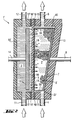
- the electrolytic cell 1 in Fig. 1 has a cathode 2 and an anode space 3.
- the liquid flows through the inlet 4 in the cathode compartment 2, the at least one of the oxidizing components such as chlorine, bromine, iodine, nitrate ions or contains oxygen.
- the liquid then flows through which here as a fixed bed from a bed of graphite grains trained with a grain size of 3 to 6 mm Cathode 5 to the outlet 6 and through this from the Electrolysis cell 1 removed.
- the flow of the catholyte is maintained and regulated by a pump and known measuring and regulating devices, which are not shown here.
- the fixed bed cathode 5 is electrically contacted with a plate 7 made of graphite. This plate 7 is firmly connected to a power supply rod or bar 8 made of electrographite.
- the cation exchange membrane 10 following the fixed bed cathode 5 in the direction of the anode compartment 3 separates the cathode 2 from the anode compartment 3 against liquid passage through the catholyte and the anolyte. It consists of a fluoropolymer doped with anionic ligands, which is commercially available under the name Nafion® 324.
- the anode space 3 follows the cation exchange membrane 10 and has an inlet 11 and an outlet 12 for the anolyte.
- the anode 13 consists of expanded titanium, which is activated with a layer of platinum mixed oxide and is marketed by De Nora Deutschland GmbH.
- the anode chamber 3 is traversed by sulfuric acid as a proton carrier, which preferably has a concentration of 10 to 35% by weight of H 2 SO 4 in the acid.
- Cathode 2 and anode compartment 3 are delimited, apart from on the cation exchange membrane 10, by a housing 15, 15 'made of polypropylene.
- a housing 15, 15 'made of polypropylene At the joints between the housing of the anode compartment 3 and that of the cathode compartment 2 there are seals 16, 16 'made of a suitable natural or synthetic rubber such as, for example, ethylene-propylene-ter-polymer rubber (EPDM), between which 16, 16' the cation exchange membrane 10 is embedded.
- EPDM ethylene-propylene-ter-polymer rubber
- FIG. 2 shows another embodiment of the electrolytic cell 1.
- this cell 1 ' has a bottom narrow and expanding cathode 5 ', the flowable space and thus the contact with the Catholyte available surface in the lower Part of the cell 1 'is comparatively small.
- This flowable space and thus the contact with the Surface available for and catholytes the time available for these touches is taken by the Shape of the cathode 5 'corresponding to the upper part of the cell 1 ', i.e. in the direction of flow constantly. Purpose one such a shape of the cathode 5 'is possible to achieve optimal sales in every cathode zone.
- the catholyte via the feed line 4 into the cathode space 2 ' occurs, it is with the oxidizing component that to be reduced electrochemically, comparatively high enriched. As a result of this high concentration almost leads every contact of the catholyte with the cathode 5 'in the lower Part of the cathode space 2 'to an electrochemical Implementation. With increasing depletion, the number of electrochemically successful touches now and then electrochemical sales are falling more and more and it is advantageous and this happens in the illustrated Cathode 5 ', the catholyte for maintaining good Sales along with reducing speed, i.e. with increasing the dwell time of the flowing Electrolytes to offer ever larger surfaces.
- the grid can also be connected to the cation exchange membrane 10, for example be welded.
- the cathode space 2 ' has a screen plate in the upper part 39, which prevents the cathode 5 'from being rinsed out, and a collection and discharge space 40 for the of oxidizing components liberate catholytes.
- This one untreated components of this electrolytic cell 1 ' correspond to the respective components of that in FIG. 1 shown electrolytic cell 1. It is on this figure referred.
- FIG. 3 shows another preferred embodiment of the Electrolysis cell 1, in particular the electrolysis cell 1 '.
- the cell 1 ′′ of FIG. 3 differs from that Electrolysis cell 1 'of Figure 2 in that it 1' 'one Has cathode space 2 '', in which the walls 17 made of liquid-tight impregnated, especially with resin and in particular graphite impregnated with a synthetic resin consist.
- the other features of the electrolytic cell correspond to those of Figure 2 and are not here once described.
- the execution of the walls 17 of the Has cathode space 2 '' in impregnated graphite the corresponding walls 15 of cells 1, 1 'of FIGS. 1 and 2 the advantage that an additional plate 7 for Contacting the cathode bed 5 'is not necessary.
- the unillustrated hole, which in Figures 1 and 2 is necessary to the power supply rod 8 through the housing 15 from the cathode compartment 2, 2 ' lead out and it is also not canceled shown seal on the implementation of the power supply rod 8 through the housing 15, which, although for State of the art, technically difficult and frequent is a source of interference.
- the impregnated graphite is good electrical conductivity.
- the power supply rod 41 has no more contact with this constructive solution the catholyte and can therefore also be made of electrically conductive Materials such as Copper or aluminum exist that are not resistant to the catholyte are.
- the wall made of impregnated graphite can also be used be contacted electrically at any suitable location. On Power supply rod 41 is no longer absolutely necessary for this. Instead, e.g. also directly to the Graphite wall 17 screwed on contact shoes, for example made of copper.
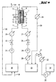
- FIG. 4 shows the implementation of the method on the basis of a schematic image, which at the same time illustrates the implementation of the tests for verifying the invention.
- the method was demonstrated using the purification of hydrochloric acid from chlorine dissolved therein.
- a certain chlorine content had to be set in a hydrochloric acid which was provided as the catholyte.
- this hydrochloric acid, which was located in the container 23, was continuously added from the storage vessel 19 by means of the pump 20 via the regulating valve 21, the equivalent of which sodium hypochlorite solution was to be reduced as in the electrolysis cell 1 chlorine to chloride.
- the sodium hypochlorite in the container 23 reacts accordingly with the hydrochloric acid NaOCl + 2 HCl ------ Cl 2 + H 2 O + NaCl.
- the position of the regulating valve 21 was regulated with the aid of the flow meter 22 and a corresponding control device.
- the hydrochloric acid contaminated with chlorine was conveyed from the storage and buffer vessel 23 by means of the pump 24 through the regulating valve 25 at the inlet point 4 into the cathode chamber 2 of the electrolytic cell 1.
- the regulation was accomplished with the help of the flow meter 26 and a control device, not shown.
- the chlorine dissolved in the hydrochloric acid was completely reduced to chloride when flowing through the fixed bed cathode 5, which in the present case consisted of graphite grains with a diameter in the range from 3 to 5 mm, so that the electrolysis cell 1 at the outlet 6 was a catholyte of pure, chlorine-free Hydrochloric acid left.
- the proton carrier returned to the storage and buffer container 30 via the pipeline 35.
- the invention is explained in more detail below using an exemplary embodiment.
- Hydrochloric acid with an HCl content of 25 percent by weight served as the catholyte.
- An aqueous sodium hypochlorite solution containing 12% by weight of NaOCl was continuously added to this hydrochloric acid in order to produce a certain chlorine concentration.
- a sulfuric acid with an H 2 SO 4 content of 25% by weight served as the anolyte.
- a test apparatus according to FIG. 4 was used. When describing FIG. 4, some circumstances have already been considered when carrying out the tests which were used to verify this invention. In the following explanations, reference is further made to the circumstances of FIG. 4.
- the redox potential of the entering into the cathode space was measured by means of the measuring device 27 equipped with an Ag / AgCl electrode and the redox potential of the hydrochloric acid leaving the cathode space was measured by means of the measuring device 28 equipped with the same electrode. It was -100 mV.
- the volume flow of the hydrochloric acid through the cathode compartment was set to 50 l / hour. After completing this basic setting, 12% sodium hypochlorite solution in the amount of 0.1 ml / minute was continuously added to the hydrochloric acid from container 19 in container 19, which led to the setting of a certain content of dissolved chlorine in the hydrochloric acid.
- the volume flow of chlorine-containing hydrochloric acid was then adjusted back to 50 l / hour.
- the redox potential in front of the cathode compartment 2 at measuring point 27 was now +900 mV due to the free chlorine content.
- the redox potential of the hydrochloric acid leaving the cathode compartment 2 at measuring point 28 was slightly more than +800 mV during the first 30 minutes thereafter.
- the redox potential dropped sharply to the previously measured reference value for chlorine-free hydrochloric acid of -100 mV and remained at this value over the entire remaining test period of over 4 hours.
- the liquid-permeable grid 9 consisted of a fabric diaphragm made of polyvinylidene fluoride. Further tests showed that the other oxidizing constituents mentioned could also be reductively converted from their solutions into desired or harmless constituents by the process according to the invention.
- the advantages of the invention are: A method and an apparatus for carrying out the method are provided, with which the above-described harmful, oxidizing constituents of liquids can be completely converted into valuable substances or into harmless constituents without great effort and without the introduction of foreign chemicals or salts. Very pure liquids which can be processed without further treatment are obtained. The process is suitable for solutions with very low as well as high contents of oxidizing substances. The liquids treated by the process have a far lower oxidation and corrosion potential than before the treatment.
Landscapes
- Chemical & Material Sciences (AREA)
- Chemical Kinetics & Catalysis (AREA)
- Electrochemistry (AREA)
- General Chemical & Material Sciences (AREA)
- Life Sciences & Earth Sciences (AREA)
- Hydrology & Water Resources (AREA)
- Engineering & Computer Science (AREA)
- Environmental & Geological Engineering (AREA)
- Water Supply & Treatment (AREA)
- Organic Chemistry (AREA)
- Electrolytic Production Of Non-Metals, Compounds, Apparatuses Therefor (AREA)
- Water Treatment By Electricity Or Magnetism (AREA)
Applications Claiming Priority (2)
| Application Number | Priority Date | Filing Date | Title |
|---|---|---|---|
| DE10004877 | 2000-02-04 | ||
| DE2000104877 DE10004877A1 (de) | 2000-02-04 | 2000-02-04 | Verfahren und Elektrolysezelle zum Reduzieren korrodierend wirkender Bestandteile in Flüssigkeiten |
Publications (2)
| Publication Number | Publication Date |
|---|---|
| EP1122216A2 true EP1122216A2 (fr) | 2001-08-08 |
| EP1122216A3 EP1122216A3 (fr) | 2002-08-07 |
Family
ID=7629783
Family Applications (1)
| Application Number | Title | Priority Date | Filing Date |
|---|---|---|---|
| EP01100151A Withdrawn EP1122216A3 (fr) | 2000-02-04 | 2001-01-16 | Procede et cellule electrolytique pour reduire des composants corrosifs dans des fluides |
Country Status (2)
| Country | Link |
|---|---|
| EP (1) | EP1122216A3 (fr) |
| DE (1) | DE10004877A1 (fr) |
Cited By (1)
| Publication number | Priority date | Publication date | Assignee | Title |
|---|---|---|---|---|
| EP1953272A1 (fr) * | 2007-02-03 | 2008-08-06 | Bayer MaterialScience AG | Procédé de déchloruration électrochimique d'une saumure d'anolyte provenant d'une électrolyse NaCI |
Families Citing this family (2)
| Publication number | Priority date | Publication date | Assignee | Title |
|---|---|---|---|---|
| DE10319044A1 (de) * | 2003-04-25 | 2004-11-11 | Bergische Universität Wuppertal | Vorrichtung zur elektrolytischen und oxidativen Behandlung von Abwässern, hierbei eingesetzte Filtrationsmembranen, deren Herstellung sowie Verfahren zur Behandlung von Abwässern mittels dieser Anlage und/oder dieser Filtrationsmembranen |
| DE102009005011A1 (de) * | 2009-01-17 | 2010-07-22 | Eilenburger Elektrolyse- Und Umwelttechnik Gmbh | Verfahren und Vorrichtung zur elektrochemischen Desinfektion von Trink- und Brauchwasser mit hohen Härtegehalten |
Citations (5)
| Publication number | Priority date | Publication date | Assignee | Title |
|---|---|---|---|---|
| US3974049A (en) * | 1973-08-03 | 1976-08-10 | Parel. Societe Anonyme | Electrochemical process |
| DE3838181A1 (de) * | 1988-11-10 | 1990-05-23 | Linde Ag | Verfahren und vorrichtung zur entfernung von stickstoffverbindungen aus waessrigen loesungen |
| US5167777A (en) * | 1990-10-30 | 1992-12-01 | Olin Corporation | Process and apparatus for the removal of oxyhalide species from aqueous solutions |
| FR2754251A1 (fr) * | 1996-10-03 | 1998-04-10 | Step | Installation et procede pour le traitement de fluides aqueux |
| DE19815669A1 (de) * | 1998-04-08 | 1999-10-14 | Univ Dresden Tech | Verfahren zur reduktiven elektrochemisch katalytischen Eliminierung von Nitrat aus konzentrierten Lösungen |
Family Cites Families (7)
| Publication number | Priority date | Publication date | Assignee | Title |
|---|---|---|---|---|
| DE2622497C2 (de) * | 1976-05-20 | 1986-03-06 | Dechema Deutsche Gesellschaft für chemisches Apparatewesen e.V., 6000 Frankfurt | Elektrochemische Zelle |
| DE2901577A1 (de) * | 1979-01-17 | 1980-07-31 | Dechema Deutsche Ges F Chem Ap | Verfahren und vorrichtung zum entfernen von gasfoermigen verunreinigungen aus gasen |
| DE2904539C2 (de) * | 1979-02-07 | 1982-08-05 | Deutsche Carbone Ag, 6000 Frankfurt | Verfahren zur elektrolytischen Abwasserreinigung mittels einer Festbettelektrolysezelle und elektrochemische Zelle zur Durchführung des Verfahrens |
| US4927509A (en) * | 1986-06-04 | 1990-05-22 | H-D Tech Inc. | Bipolar electrolyzer |
| US5376240A (en) * | 1991-11-04 | 1994-12-27 | Olin Corporation | Process for the removal of oxynitrogen species for aqueous solutions |
| DE19531707A1 (de) * | 1995-08-30 | 1997-03-06 | Degussa | Verfahren zur Reinigung von Gasen |
| DE19614018A1 (de) * | 1996-04-09 | 1997-10-16 | Degussa | Verfahren und Elektrolysezelle zur Reinigung von Gasen |
-
2000
- 2000-02-04 DE DE2000104877 patent/DE10004877A1/de not_active Withdrawn
-
2001
- 2001-01-16 EP EP01100151A patent/EP1122216A3/fr not_active Withdrawn
Patent Citations (5)
| Publication number | Priority date | Publication date | Assignee | Title |
|---|---|---|---|---|
| US3974049A (en) * | 1973-08-03 | 1976-08-10 | Parel. Societe Anonyme | Electrochemical process |
| DE3838181A1 (de) * | 1988-11-10 | 1990-05-23 | Linde Ag | Verfahren und vorrichtung zur entfernung von stickstoffverbindungen aus waessrigen loesungen |
| US5167777A (en) * | 1990-10-30 | 1992-12-01 | Olin Corporation | Process and apparatus for the removal of oxyhalide species from aqueous solutions |
| FR2754251A1 (fr) * | 1996-10-03 | 1998-04-10 | Step | Installation et procede pour le traitement de fluides aqueux |
| DE19815669A1 (de) * | 1998-04-08 | 1999-10-14 | Univ Dresden Tech | Verfahren zur reduktiven elektrochemisch katalytischen Eliminierung von Nitrat aus konzentrierten Lösungen |
Cited By (1)
| Publication number | Priority date | Publication date | Assignee | Title |
|---|---|---|---|---|
| EP1953272A1 (fr) * | 2007-02-03 | 2008-08-06 | Bayer MaterialScience AG | Procédé de déchloruration électrochimique d'une saumure d'anolyte provenant d'une électrolyse NaCI |
Also Published As
| Publication number | Publication date |
|---|---|
| DE10004877A1 (de) | 2001-08-09 |
| EP1122216A3 (fr) | 2002-08-07 |
Similar Documents
| Publication | Publication Date | Title |
|---|---|---|
| DE10216860B4 (de) | Elektrolysevorrichtung für die Herstellung von Wasserstoffperoxid und Verfahren zur Herstellung von Wasserstoffperoxid | |
| DE19540469B4 (de) | Vorrichtung und Verfahren zur Erzeugung von elektrolytisch ionisiertem Wasser | |
| EP1065170B1 (fr) | Procédé et dispositif pour régler électrolytiquement le ph et le potentiel redox de fluides | |
| EP0068522B1 (fr) | Procédé et installation pour la préparation synthétique d'ozone par electrolyse et son application | |
| EP3317435B1 (fr) | Procédé de réduction et système d'électrolyse permettant le recyclage électrochimique du dioxyde de carbone | |
| EP1600426B1 (fr) | Procédé et dispositif pour la séparation des anions sulfates de l'eau et pour apporter un pouvoir tampon à l'eau | |
| AT401739B (de) | Vorrichtung zur aufbereitung von metallhaltigen flüssigkeiten durch ionenaustausch und gleichzeitige oder periodische regenerierung des ionenaustauscherharzes durch elektrodialyse | |
| DE19530086C2 (de) | Verfahren zur physikalisch-chemischen Brauchwasseraufbereitung von Oberflächen- und Abwässern | |
| DE3221253A1 (de) | Elektrolytischer chlorgasgenerator | |
| DE2604371A1 (de) | Verfahren zum elektrochemischen entfernen verunreinigender ionen aus einem ionisierenden medium sowie elektrochemische zelle zur durchfuehrung des verfahrens | |
| EP3885471A1 (fr) | Procédé amélioré de fabrication d'alcools de sodium | |
| EP3714083A1 (fr) | Cellule d'électrode à diffusion gazeuse double sans séparateur, destinée à une conversion électrochimique | |
| DE2523117A1 (de) | Verfahren und vorrichtung zur regeneration einer dekapierloesung | |
| EP0800853B1 (fr) | Procédé et cellule d'électrolyse pour purifier des gaz | |
| DE2922275C2 (de) | Verfahren zum Chlorieren und Bromieren von Wasser in einer Elektrolysezelle und Vorrichtung dafür | |
| DE2451846A1 (de) | Verfahren zur elektrolytischen herstellung von metallhydroxidloesungen | |
| DE2901577C2 (fr) | ||
| EP1122216A2 (fr) | Procede et cellule electrolytique pour reduire des composants corrosifs dans des fluides | |
| DE2244244C3 (de) | Elektrolytische Verfahren zum Entfernen einer in einer wäßrigen verbrauchten Lösung gelösten verunreinigenden Substanz sowie dazu verwendbare regenerative elektrolytische Zelle | |
| EP0761285A2 (fr) | Procédé pour la purification de gaz | |
| WO2022043290A1 (fr) | Appareil et procédé pour effectuer une électrolyse | |
| DE4312600C2 (de) | Kleinentsalzungsanlage auf Ionenaustauscherbasis mit elektrolytisch herstellbaren Regeneriermitteln | |
| EP0814060A2 (fr) | Procédé pour augmenter le pH des eaux acides | |
| DE2316238A1 (de) | Verfahren zum entfernen von schwermetallen aus waessriger loesung | |
| DE19953056B4 (de) | Elektrochemisches Verfahren zum Abbau von Organometallverbindungen in Baggergut und Anlage zur Durchführung des Verfahrens |
Legal Events
| Date | Code | Title | Description |
|---|---|---|---|
| PUAI | Public reference made under article 153(3) epc to a published international application that has entered the european phase |
Free format text: ORIGINAL CODE: 0009012 |
|
| AK | Designated contracting states |
Kind code of ref document: A2 Designated state(s): AT BE CH CY DE DK ES FI FR GB GR IE IT LI LU MC NL PT SE TR |
|
| AX | Request for extension of the european patent |
Free format text: AL;LT;LV;MK;RO;SI |
|
| PUAL | Search report despatched |
Free format text: ORIGINAL CODE: 0009013 |
|
| AK | Designated contracting states |
Kind code of ref document: A3 Designated state(s): AT BE CH CY DE DK ES FI FR GB GR IE IT LI LU MC NL PT SE TR |
|
| AX | Request for extension of the european patent |
Free format text: AL;LT;LV;MK;RO;SI |
|
| RIC1 | Information provided on ipc code assigned before grant |
Free format text: 7C 02F 1/46 A, 7C 02F 1/461 B |
|
| AKX | Designation fees paid | ||
| REG | Reference to a national code |
Ref country code: DE Ref legal event code: 8566 |
|
| STAA | Information on the status of an ep patent application or granted ep patent |
Free format text: STATUS: THE APPLICATION IS DEEMED TO BE WITHDRAWN |
|
| 18D | Application deemed to be withdrawn |
Effective date: 20030530 |