EP1122137B1 - Wischerlagerung - Google Patents
Wischerlagerung Download PDFInfo
- Publication number
- EP1122137B1 EP1122137B1 EP01102122A EP01102122A EP1122137B1 EP 1122137 B1 EP1122137 B1 EP 1122137B1 EP 01102122 A EP01102122 A EP 01102122A EP 01102122 A EP01102122 A EP 01102122A EP 1122137 B1 EP1122137 B1 EP 1122137B1
- Authority
- EP
- European Patent Office
- Prior art keywords
- pivot
- shaft
- wiper
- walled
- thin
- Prior art date
- Legal status (The legal status is an assumption and is not a legal conclusion. Google has not performed a legal analysis and makes no representation as to the accuracy of the status listed.)
- Expired - Lifetime
Links
- 238000000465 moulding Methods 0.000 claims description 2
- 239000011347 resin Substances 0.000 claims description 2
- 229920005989 resin Polymers 0.000 claims description 2
- 238000010008 shearing Methods 0.000 claims description 2
- 238000005192 partition Methods 0.000 description 2
- 238000005452 bending Methods 0.000 description 1
- 230000001419 dependent effect Effects 0.000 description 1
- 230000000694 effects Effects 0.000 description 1
Images


Classifications
-
- B—PERFORMING OPERATIONS; TRANSPORTING
- B60—VEHICLES IN GENERAL
- B60S—SERVICING, CLEANING, REPAIRING, SUPPORTING, LIFTING, OR MANOEUVRING OF VEHICLES, NOT OTHERWISE PROVIDED FOR
- B60S1/00—Cleaning of vehicles
- B60S1/02—Cleaning windscreens, windows or optical devices
- B60S1/04—Wipers or the like, e.g. scrapers
- B60S1/32—Wipers or the like, e.g. scrapers characterised by constructional features of wiper blade arms or blades
- B60S1/34—Wiper arms; Mountings therefor
-
- B—PERFORMING OPERATIONS; TRANSPORTING
- B60—VEHICLES IN GENERAL
- B60S—SERVICING, CLEANING, REPAIRING, SUPPORTING, LIFTING, OR MANOEUVRING OF VEHICLES, NOT OTHERWISE PROVIDED FOR
- B60S1/00—Cleaning of vehicles
- B60S1/02—Cleaning windscreens, windows or optical devices
- B60S1/04—Wipers or the like, e.g. scrapers
- B60S1/0413—Modular wiper assembly
- B60S1/0422—Modular wiper assembly having a separate transverse element
- B60S1/0425—Modular wiper assembly having a separate transverse element characterised by the attachment of the wiper shaft holders to the transverse element
-
- B—PERFORMING OPERATIONS; TRANSPORTING
- B60—VEHICLES IN GENERAL
- B60S—SERVICING, CLEANING, REPAIRING, SUPPORTING, LIFTING, OR MANOEUVRING OF VEHICLES, NOT OTHERWISE PROVIDED FOR
- B60S1/00—Cleaning of vehicles
- B60S1/02—Cleaning windscreens, windows or optical devices
- B60S1/04—Wipers or the like, e.g. scrapers
- B60S1/043—Attachment of the wiper assembly to the vehicle
- B60S1/0433—Attachement of a wiper modular assembly to the vehicle
-
- B—PERFORMING OPERATIONS; TRANSPORTING
- B60—VEHICLES IN GENERAL
- B60S—SERVICING, CLEANING, REPAIRING, SUPPORTING, LIFTING, OR MANOEUVRING OF VEHICLES, NOT OTHERWISE PROVIDED FOR
- B60S1/00—Cleaning of vehicles
- B60S1/02—Cleaning windscreens, windows or optical devices
- B60S1/04—Wipers or the like, e.g. scrapers
- B60S1/0488—Wiper arrangement for crash protection or impact absorption
-
- B—PERFORMING OPERATIONS; TRANSPORTING
- B60—VEHICLES IN GENERAL
- B60S—SERVICING, CLEANING, REPAIRING, SUPPORTING, LIFTING, OR MANOEUVRING OF VEHICLES, NOT OTHERWISE PROVIDED FOR
- B60S1/00—Cleaning of vehicles
- B60S1/02—Cleaning windscreens, windows or optical devices
- B60S1/04—Wipers or the like, e.g. scrapers
- B60S1/32—Wipers or the like, e.g. scrapers characterised by constructional features of wiper blade arms or blades
- B60S1/34—Wiper arms; Mountings therefor
- B60S1/3488—Means for mounting wiper arms onto the vehicle
- B60S1/349—Means for mounting the wiper bearing to the vehicle body
-
- F—MECHANICAL ENGINEERING; LIGHTING; HEATING; WEAPONS; BLASTING
- F16—ENGINEERING ELEMENTS AND UNITS; GENERAL MEASURES FOR PRODUCING AND MAINTAINING EFFECTIVE FUNCTIONING OF MACHINES OR INSTALLATIONS; THERMAL INSULATION IN GENERAL
- F16B—DEVICES FOR FASTENING OR SECURING CONSTRUCTIONAL ELEMENTS OR MACHINE PARTS TOGETHER, e.g. NAILS, BOLTS, CIRCLIPS, CLAMPS, CLIPS OR WEDGES; JOINTS OR JOINTING
- F16B2200/00—Constructional details of connections not covered for in other groups of this subclass
- F16B2200/63—Frangible connections
-
- Y—GENERAL TAGGING OF NEW TECHNOLOGICAL DEVELOPMENTS; GENERAL TAGGING OF CROSS-SECTIONAL TECHNOLOGIES SPANNING OVER SEVERAL SECTIONS OF THE IPC; TECHNICAL SUBJECTS COVERED BY FORMER USPC CROSS-REFERENCE ART COLLECTIONS [XRACs] AND DIGESTS
- Y10—TECHNICAL SUBJECTS COVERED BY FORMER USPC
- Y10S—TECHNICAL SUBJECTS COVERED BY FORMER USPC CROSS-REFERENCE ART COLLECTIONS [XRACs] AND DIGESTS
- Y10S403/00—Joints and connections
- Y10S403/03—Load-responsive release
Definitions
- the invention refers to a wiper pivot for a wiper apparatus of motor vehicles according to the preamble of claim 1 and as disclosed in WO-A-96/20101 .
- a wiper pivot to be used in the wiper linkage 50 shown in FIG.8 has been known.
- a pair of wiper pivots 51 and 52 are used in the wiper linkage 50 shown in FIG.8 , and the first and second wiper pivots 51 and 52 are secured at the both ends of a pipe frame 55, respectively.
- the first and second wiper pivots 51 and 52 are respectively formed with a first and a second pivot holder 51a and 52a for rotatably supporting a first and a second pivot shaft 53 and 54 respectively and body-fixing portions 51b and 52b.
- the first and second wiper pivots 51 and 52 are fixed by screwing the respective body-fixing portions 51b and 52b on an inner panel disposed on the under side of a cowl top panel (not shown).
- the top ends of the first and second pivot shafts 53 and 54 are disposed protrudingly from the cowl top panel, and secured respectively with wiper arms fitted with wiper blades.
- the first and second pivot shafts 53 and 54 are connected to base ends of a first and a second pivot arm 56 and 57 which form a part of linkage 62 at the respective base ends thereof, and a first link connecting rod 58 which forms another part of the linkage 62 is connected between the respective free ends of the first and second pivot arms 56 and 57.
- a second link connecting rod 59 which forms another part of the linkage 62 is connected to a position near to the free ends of the first pivot arm 56, and another end of the second link connecting rod 59 is connected to the free end of a motor arm 60 which forms the other part of the linkage 62.
- the motor arm 60 is secured with an output shaft 61a of a wiper motor 61 at the base end thereof.
- the wiper pivot according to this invention, if an object collides with the pivot shaft disposed protrudingly from the vehicle body panel and large impulsive force exceeding the predetermined value is applied to the pivot shaft, the destructible portion of the pivot holder is destroyed, whereby the shaft holding portion and the body-fixing portion of the pivot holder are separated from each other and the pivot holder is displaced in the direction of the vehicle body panel. Therefore, the large impulsive force can not be applied to the object even if the object collides with the pivot shaft.
- the wiper pivot 1 shown in figures is composed mainly of a pivot shaft 2, a pivot holder 3 and a destructible portion 4.
- the pivot shaft 2 is formed with a pivot arm-fitting portion (not shown) at the base end of a round rod-shaped shaft body 2a.
- the shaft body 2a of the pivot shaft 2 is formed with a pin-groove 2c at a position near to the top end thereof.
- a wiper arm-fitting portion 2d is formed at the top end of the shaft body 2a on the upper side of the pin-groove 2c of the pivot shaft 2.
- the shaft body 2a of the pivot shaft 2 is inserted rotatably in a shaft hole 3b3 formed in the pivot holder 3.
- a pivot arm 5 is secured through a wave washer (not shown) by caulking at a pivot shaft-fixing portion 5a thereof.
- a C-shaped pin (stopper) 6 is fitted in the pin-groove 2c of the pivot shaft 2.
- the outer diameter of the C-shaped pin 6 is larger than the outer diameter of the shaft body 2a of the pivot shaft 2.
- a plain washer 7 is disposed between the C-shaped pin 6 and a first projection 3b1 of the shaft-holding portion 3b of the pivot holder 3.
- the inner diameter of the plain washer 7 is slightly larger than the outer diameter of the shaft body 2a of the pivot shaft 2 and the outer diameter of the plain washer 7 is larger than the inner diameter of a shaft hole 3b3 formed in the pivot holder 3.
- the plain washer 7 is in contact with the first projection 3b1 of the shaft-holding portion 3b.
- the pivot arm 5 is secured at the base end of the shaft body 2a of the pivot shaft 2 and the C-shaped pin 6 is attached to the pivot shaft 2 through the plain washer 7 at the position near to the top end of the shaft body 2a. Accordingly, the pivot shaft 2 is prevented to come out from the shaft hole 3b3 formed in the shaft-holding portion 3b of the pivot holder 3.
- the pivot shaft 2 is formed with a positive screw 2d1 and a serration 2d2 at the wiper arm-fitting portion 2d.
- the wiper arm-fitting portion 2d of the pivot shaft 2 is passed through a securing portion 20a formed in the base end of a wiper arm 20 shown in FIG.7 , whereby the serration 2d2 of the pivot shaft 2 is engaged with a serration receiver (not shown) formed at the securing portion 20a of the wiper arm 20.
- the positive screw 2d1 of the pivot shaft 2 is pierced into a hole formed in the securing portion 20a and is screwed into a nut (not shown), thereby securing the wiper arm 20 on the wiper arm-fitting portion 2d of the pivot shaft 2.
- a wiper blade 21 is fitted to the top end of the wiper arm 20 as shown in FIG.7 .
- the pivot arm 2 is disposed so that the wiper arm-fitting portion 2d of the pivot arm 2 may be protruded from a pivot hole 70a formed in a cowl top panel (body panel) 70 shown in FIG.7 .
- the wiper arm 20 fitted with the wiper blade 21 is secured to the pivot shaft 2. Therefore, if large impulsive force is applied to the wiper blade 21 or the wiper arm 20, the impulsive energy caused by the impulsive force is given to the shaft-holding portion 3b of the pivot holder 3 through the pivot shaft 2, the C-shaped pin 6 and the plain washer 7.
- the pivot holder 3 is formed of resin and provided with a holder body 3a, a connecting portion 3c, a body-fixing portion 3d and a frame-connecting portion 3e in addition to the shaft-holding portion 3b described above in a united one body.
- the holder body 3a is formed in a rectangular shape and disposed in the substantially center of the pivot holder 3.
- the shaft-holding portion 3b is formed in the center of the holder body 3a.
- the shaft-holding portion 3b is formed in a hollow cylindrical shape, and formed with the first projection 3b1 protruding on the upper side of the holder body 3a and a second projection 3b2 protruding on the lower side of the holder body 3a.
- the first projection 3b1 of the shaft-holding portion 3b is in contact with the plain washer 7 and the second projection 3b2 of the shaft-holding portion 3b is in contact with the wave washer (not shown) as described above.
- the shaft-holding portion 3b is formed with the shaft hole 3b3 opened from the first projection 3b1 toward the second projection 3b2, and inserted rotatably with the shaft body 2a of the pivot shaft 2.
- the connecting portion 3c is disposed so as to bridge between the holder body 3a and the body-fixing portion 3d on the right side of the holder body 3a shown in FIG.2 .
- the connecting portion 3c is formed with the destructible portion 4.
- the destructible portion 4 is composed of a first thin-walled portion 4a, a second thin-walled portion 4b and a third thin-walled portion 4c.
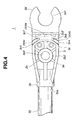
- the first thin-walled portion 4a of the destructible portion 4 is disposed in the center of the connecting portion 3c, and formed in a thin-walled shape on the side of a lower face 3c2 of a first hollow 3c3 cut out in a rectangular shape toward the lower face 3c2 from an upper face 3c1 of the connecting portion 3c.
- the first thin-walled portion 4a has thickness t2 sufficiently smaller than height t1 of the connecting portion 3c as shown in FIG.5 .
- the first thin-walled portion 4a and the first hollow 3c3 are formed in arcuate shapes on the circumference of a circle with a diameter of "r1" about the same center "a", which is also the center of the shaft hole 3b3 of the shaft-holding portion 3b as shown in FIG.3 .
- the second thin-walled portion 4b of the destructible portion 4 is disposed on one side of the lateral of the connecting portion 3c, and formed in a thin-walled shape on the side of the upper face 3c1 of a second hollow 3c4 cut out in a rectangular shape toward the upper face 3c1 from the lower face 3c2 of the connecting portion 3c.
- the second thin-walled portion 4b has thickness t2 equal to the thickness of the first thin-walled portion 4a and sufficiently smaller than the height t1 of the connecting portion 3c as shown in FIG.6 .
- the second thin-walled portion 4b and the second hollow 3c4 are formed in arcuate shapes on the circumference of the circle with the diameter of "r1" about the center “a” of the shaft hole 3b3 of the shaft-holding portion 3b.
- a partition wall 3c6 is disposed between the first hollow 3c3 and the second hollow 3c4, and the second hollow 3c4 has an opening on the opposite side of that of the first hollow 3c3.
- the third thin-walled portion 4c of the destructible portion 4 is disposed on the other side of the lateral of the connecting portion 3c so as to form a pair together with the second thin-walled portion 4b.
- the third thin-walled portion 4c is formed also in a thin-walled shape on the side of the upper face 3c1 of a third hollow 3c5 cut out in a rectangular shape toward the upper face 3c1 from the lower face 3c2 of the connecting portion 3c.
- the third thin-walled portion 4c is sufficiently small as compared with the height t1 of the connecting portion 3c and has thickness t2 equivalent to the thickness of the first and second thin-walled portions 4a and 4b as shown in FIG.6 .
- the third thin-walled portion 4c and the third hollow 3c5 are formed in arcuate shapes on the circumference of the circle with the diameter of "r1" about the center “a” of the shaft hole 3b3 in the shaft-holding portion 3b.
- a partition wall 3c7 is disposed between the first hollow 3c3 and the third hollow 3c5 and the third hollow 3c5 is opened on the opposite side of the opening of the first hollow 3c3.
- the second thin-walled portion 4b, the first thin-walled portion 4a and the third thin-walled portion 4c of the destructible portion 4 are disposed continuously in the circumferential direction of the shaft hole 3b3 of the shaft-holding portion 3b between the shaft-holding portion 3b and the body-fixing portion 3d. Therefore, the connecting portion 3c is destroyed by absorbing the striking energy caused by shearing stress, bending stress or torsional stress applied on the shaft-holding portion 3b through the plain washer 7 from the C-shaped pin 6 at the time when the large impulsive force is applied on the wiper blade 21 or the wiper arm 20. Consequently, the shaft-holding portion 3b and the holder body 3a are separated from the body-fixing portion 3d.
- the striking energy applied to the shaft-holding portion 3b is uniformly given against the first, second and third thin-walled portions 4a, 4b and 4c, and the striking energy is absorbed infallibly by the destructible portion 4 because the first, second and third thin-walled portions 4a, 4b and 4c are formed in arcuate shapes on the circumference of the circle about the center "a" of the shaft hole 3b3 in the shaft-holding portion 3b.
- the body-fixing portion 3d of the pivot holder 3 is formed continuously from the connecting portion 3c on the right side of the connecting portion 3c in FIG.2 .
- the body-fixing portion 3d is fitted with a shock-absorbable damper 8 made of rubber in a damper-fitting portion 3d1 formed in a forked shape.
- a bolt (not shown) is passed through the damper 8 and screwed into the inner panel such as a dash upper panel disposed on the lower side of the cowl top panel, thereby securing the pivot holder 3 on the vehicle body at the body-fixing portion 3d.
- the frame-connecting portion 3e of the pivot holder 3 is formed continuously from the holder body 3a on the left side of the shaft-holding portion 3b in FIG.2 .
- the frame-connecting portion 3e is formed at the end 55a of the pipe frame 55 (see FIG.8 ) through the outsert moulding together with the holder body 3a, the shaft-holding portion 3b, the connecting portion 3c and the body-fixing portion 3d.
- the end 55a of the pipe frame 55 is compressed in a plate-like shape to form a plate portion 55a1, and formed with a round hole 55a2 in the plate portion 55a1.
- the shaft-holding portion 3b of the pivot holder 3 is moulded so as to locate the shaft hole 3b3 in the hole 55a2 as shown in FIG.5 .
- a pair of such the wiper pivots 1 are disposed to the both ends of the wiper frame 55 of the wiper linkage 50 as shown similarly in FIG.8 , and mounted on the vehicle body by screwing the body-fixing portions 3d of the respective wiper pivots 1 on the inner panel of the vehicle body, furthermore the wiper arms 20 and the wiper blades 21 are fitted on the respective pivot shafts 2 protruding from the pivot holes 70a of the cowl top panel 70.
- the wiper pivot 1 structured as mentioned above, if the predetermined large impulsive force is applied to the wiper arm 20, the wiper blade 21 or the pivot shaft 2 by the collision with the object or body, the impulsive force is given to the shaft-holding portion 3b through the plain washer 7 from the C-shaped washer 6 of the pivot shaft 2, whereby the first, second and third thin-walled portions 4a, 4b and 4c of the destructible portion 4 are cut off by the impulsive force and the shaft-holding portion 4b and the holder body 3a are separated from the body-fixing portion 3d.
- the pivot shaft 2 is dislocated from the predetermined position in the pivot holder 3 and displaced in the lower direction of the cowl top panel, the impulsive force is received by the body panel having a plane portion and elasticity as compared with the pivot shaft 2, and it is possible to reduce the impulsive force applied on the object.
- the destructible portion of the pivot holder is destroyed in the case where the object collides with the pivot shaft disposed protrudingly on the body panel and large impulsive force exceeding the predetermined value is applied on the pivot shaft, whereby the shaft-holding portion is separated from the body-fixing portion of the pivot holder and it is possible to displace the pivot shaft in the direction of the body panel. Accordingly, an excellent effect can be obtained in that the large impulsive force is not applied on the object even if the object collides with the pivot shaft of the wiper pivot from the outside.
Landscapes
- Engineering & Computer Science (AREA)
- Mechanical Engineering (AREA)
- Pivots And Pivotal Connections (AREA)
- Body Structure For Vehicles (AREA)
- Transmission Devices (AREA)
Claims (5)
- Wischerlagerung (1) für eine Wischervorrichtung von Kraftfahrzeugen, aufweisend:eine Lagerachse (2), die mit einem Fußende versehen ist, welches mit einem Wischermotor (61) über eine Wischerverbindung verbunden ist, und ein Kopfende, welches vorspringend von einem Gehäusepanel (70) des Fahrzeugs angeordnet und mit einem Wischerarm (20) verbunden ist, an welchem ein Wischerblatt (21) angebracht ist; und eine Lagerhalterung (3), die aus Harz hergestellt ist und mit einem Achsenhalterungs-Abschnitt (3b) versehen ist, welcher ein Achsenloch (3b3) zum drehbaren Tragen der Lagerachse (2) und einen Gehäuse-Befestigungsaschnitt (3d) aufweist, der an dem Gehäusepanel (70) des Fahrzeugs befestigt wird, welches aus einem Gehäuse zusammen mit dem Achsenhalterungsabschnitt (3b) über einen Verbindungsabschnitt (3c) gebildet ist;wobei der Verbindungsabschnitt (3c) der Wischerlagerung (3) mit einer Vielzahl dünnwandiger zerstörbarer Abschnitte (4) versehen ist, die zu einem Zeitpunkt zerstört werden, wenn eine impulsive Kraft, die einen vorherbestimmten Wert übersteigt, auf die Lagerachse (2) einwirkt, und wobei der Verbindungsabschnitt (3c) eine untere Fläche (3c2) und eine obere Fläche (3c1) aufweist, welche in einer vorherbestimmten Distanz in der axialen Richtung der Lagerhalterung (3) von einander beabstandet sind, wobei die zerstörbaren Abschnitte (4) des Verbindungsabschnitts (3) einen oberen dünnwandigen Abschnitt (4b, 4c), welcher mit der oberen Fläche (3c1) gebildet wird, und einen unteren dünnwandigen Abschnitt (4a) aufweisen, welcher mit der unteren Fläche (3c2) gebildet wird;
dadurch gekennzeichnet, dass
der untere dünnwandige Abschnitt einen ersten dünnwandigen Abschnitt (4a) beinhaltet, welcher an dem Mittelpunkt des Verbindungsabschnitts (3c) gebildet ist, und
der obere dünnwandige Abschnitt zweite und dritte dünnwandige Abschnitte (4b, 4c) beinhaltet, die auf beiden Seiten des Verbindungsabschnitts (3c) der Lagerhalterung (3) gebildet sind. - Wischerlagerung nach Anspruch 1, wobei die oberen und unteren dünnwandigen Abschnitte (4a, 4b, 4c) des zerstörbaren Abschnitts (4) des Verbindungsabschnitts (3c) in bogenförmigen Formen gebildet sind, welche den Mittelpunkt identisch mit dem des Achsenlochs der Lagerhalterung aufweisen.
- Wischerlagerung nach einem der Ansprüche 1 oder 2, wobei die Dicke (t2) der oberen und unteren dünnwandigen Abschnitte (4a, 4b, 4c) des zerstörbaren Abschnitts (4) des Verbindungsabschnitts (3c) ausreichend kleiner als der Abstand (t1) zwischen den oberen und unteren dünnwandigen Abschnitten (4a, 4b, 4c) ist.
- Wischerlagerung nach einem der Ansprüche 1 bis 3, wobei die Achsenhalterung (3) mit einem Ende (55a) des Leitungsrahmens (55) der Wischerverbindung bei dem Achsenhalterungsabschnitt (3b) über Outsert-Moulding verbunden ist.
- Wischerlagerung nach einem der Ansprüche 1 bis 3, wobei der zerstörbare Abschnitt (4) des Verbindungsabschnitts (3c) derartig ausgebildet ist, um zerstört zu werden und um den Achsenhalterungsabschnitt (3b) der Lagerhalterung (3) von dem Gehäuse-Befestigungsabschnitt (3d) der Lagerhalterung (3) durch Schubspannung zu trennen, die zwischen dem Achsenhalterungsabschnitt (3b) und dem Gehäuse-Befestigungsabschnitt (3d) der Lagerhalterung (3) verursacht wird.
Applications Claiming Priority (2)
| Application Number | Priority Date | Filing Date | Title |
|---|---|---|---|
| JP2000028004 | 2000-02-04 | ||
| JP2000028004A JP4081216B2 (ja) | 2000-02-04 | 2000-02-04 | ワイパピボット |
Publications (3)
| Publication Number | Publication Date |
|---|---|
| EP1122137A2 EP1122137A2 (de) | 2001-08-08 |
| EP1122137A3 EP1122137A3 (de) | 2003-10-29 |
| EP1122137B1 true EP1122137B1 (de) | 2008-08-27 |
Family
ID=18553488
Family Applications (1)
| Application Number | Title | Priority Date | Filing Date |
|---|---|---|---|
| EP01102122A Expired - Lifetime EP1122137B1 (de) | 2000-02-04 | 2001-01-31 | Wischerlagerung |
Country Status (4)
| Country | Link |
|---|---|
| US (2) | US6718592B2 (de) |
| EP (1) | EP1122137B1 (de) |
| JP (1) | JP4081216B2 (de) |
| DE (1) | DE60135514D1 (de) |
Families Citing this family (31)
| Publication number | Priority date | Publication date | Assignee | Title |
|---|---|---|---|---|
| DE19925291A1 (de) * | 1999-06-02 | 2000-12-07 | Bosch Gmbh Robert | Scheibenwischeranlage |
| JP4081216B2 (ja) * | 2000-02-04 | 2008-04-23 | 株式会社ミツバ | ワイパピボット |
| JP4708560B2 (ja) | 2000-12-28 | 2011-06-22 | 富士重工業株式会社 | 車両用ワイパ装置 |
| US6845540B1 (en) | 2002-04-30 | 2005-01-25 | Valeo Electrical Systems, Inc. | Wiper pivot housing with spring release pivot shaft |
| US6701569B1 (en) | 2002-04-30 | 2004-03-09 | Valeo Electrical Systems, Inc. | Wiper pivot housing with frangible mount |
| KR100450295B1 (ko) * | 2002-05-15 | 2004-09-30 | 동양기전 주식회사 | 자동차용 와이퍼 링케이지 및 이의 제작 방법 |
| FR2840270B1 (fr) * | 2002-05-28 | 2004-12-10 | Valeo Systemes Dessuyage | Agencement de securite permettant une separation du bras d'essuyage d'avec l'arbre d'entrainement en cas d'impact |
| FR2846288B1 (fr) * | 2002-10-28 | 2005-01-14 | Valeo Systemes Dessuyage | Agencement de securite permettant une separation en deux elements de la tete d'entrainement d'un bras d'essuie-glace |
| US7191487B2 (en) | 2002-12-30 | 2007-03-20 | Valeo Electrical Systems, Inc. | Vehicle wiper apparatus with energy absorption collapsible pivot shaft |
| US7144065B2 (en) | 2002-12-30 | 2006-12-05 | Valeo Electrical Systems, Inc. | Vehicle liftgate with accessory component module |
| US6834906B2 (en) | 2002-12-30 | 2004-12-28 | Valeo Electrical Systems, Inc. | Vehicle liftgate with component module applique |
| US7246840B2 (en) * | 2003-01-31 | 2007-07-24 | Valeo Electrical Systems, Inc. | Vehicle liftgate window component module |
| JP4089473B2 (ja) | 2003-03-12 | 2008-05-28 | 株式会社ジェイテクト | ブラケット一体型リザーブタンク |
| DE10325736A1 (de) * | 2003-06-06 | 2004-12-23 | Robert Bosch Gmbh | Scheibenwischervorrichtung, insbesondere für ein Kraftfahrzeug |
| DE10329568A1 (de) * | 2003-06-30 | 2005-01-27 | Robert Bosch Gmbh | Scheibenwischvorrichtung für ein Kraftfahrzeug |
| DE102004008333A1 (de) | 2004-02-20 | 2005-09-15 | Robert Bosch Gmbh | Scheibenwischvorrichtung |
| DE102004009279A1 (de) * | 2004-02-26 | 2005-09-15 | Robert Bosch Gmbh | Scheibenwischvorrichtung, insbesondere für ein Kraftfahrzeug |
| US7537256B2 (en) * | 2004-03-02 | 2009-05-26 | Valeo Electrical Systems, Inc. | Component module applique for vehicle lift gate |
| FR2868375B1 (fr) * | 2004-04-01 | 2006-06-02 | Valeo Systemes Dessuyage | Agencement pour la fixation d'un mecanisme d'essuyage |
| KR100622731B1 (ko) | 2004-06-22 | 2006-09-14 | 기아자동차주식회사 | 충격 완충용 와이퍼 피봇 구조 |
| US7861364B2 (en) | 2005-03-21 | 2011-01-04 | Albany Magneto Equipment, Inc. | Ball and socket joint utilizing a single ball, for driving more than one driven member |
| GB2449812B (en) * | 2005-04-04 | 2009-05-13 | Trico Products Corp | Breakaway mounting bracket assembly for a wiper system |
| US7716779B2 (en) * | 2005-05-31 | 2010-05-18 | Albany Magneto Equipment, Inc. | Windshield wiper drive alignment |
| US7739771B2 (en) * | 2006-05-24 | 2010-06-22 | Albany Magneto Equipment, Inc. | Windshield wiper drive assembly with dual sector gear drive |
| KR100805939B1 (ko) * | 2006-11-07 | 2008-02-21 | 주식회사 캄코 | 와이퍼 피봇 하우징 |
| DE102006061675A1 (de) * | 2006-12-28 | 2008-07-03 | Robert Bosch Gmbh | Scheibenwischvorrichtung |
| US8516647B2 (en) * | 2009-10-14 | 2013-08-27 | Trico Products Corporation | Collapsible pivot body for a windshield wiper system |
| US8745810B2 (en) * | 2010-11-15 | 2014-06-10 | Trico Products Corporation | Pivot body for windshield wiper system |
| DE102011090155A1 (de) * | 2011-12-30 | 2013-07-04 | Robert Bosch Gmbh | Trägerelement für einen Wischerantrieb |
| JP5804276B2 (ja) * | 2012-04-25 | 2015-11-04 | 三菱自動車工業株式会社 | 車両のフロントワイパ装置の支持構造 |
| DE102013212045A1 (de) * | 2013-06-25 | 2015-01-08 | Robert Bosch Gmbh | Antriebseinrichtung für eine Scheibenwischvorrichtung |
Family Cites Families (9)
| Publication number | Priority date | Publication date | Assignee | Title |
|---|---|---|---|---|
| IT214971Z2 (it) * | 1988-11-30 | 1990-07-30 | Magneti Marelli Spa | Dispositivo tergi lava cristallo in particolare per il cristallo posteriore di un autoveicolo |
| FR2724890B1 (fr) * | 1994-09-28 | 1996-12-13 | Valeo Systemes Dessuyage | Platine-support pour un mecanisme d'essuie-glace |
| DE4446315A1 (de) * | 1994-12-23 | 1996-06-27 | Teves Gmbh Alfred | Scheibenwischeranlage mit einem geräusch- bzw. schwingungsdämpfenden Befestigungsmittel |
| FR2733474B1 (fr) | 1995-04-28 | 1997-06-06 | Valeo Systemes Dessuyage | Dispositif d'essuyage pour vehicule automobile comportant une platine de fixation a amorce de rupture, et platine appartenant a un tel dispostif |
| FR2757914B1 (fr) * | 1996-12-27 | 1999-03-05 | Valeo Systemes Dessuyage | Systeme d'essuyage comportant un palier en matiere plastique |
| JP3457153B2 (ja) * | 1997-07-24 | 2003-10-14 | 本田技研工業株式会社 | 車両用ワイパー装置 |
| JP3423870B2 (ja) * | 1997-11-11 | 2003-07-07 | 自動車電機工業株式会社 | 自動車用ワイパー |
| US6317918B1 (en) * | 1998-04-24 | 2001-11-20 | Honda Giken Kogyo Kabushiki Kaisha | Windshield wiper device for vehicle |
| JP4081216B2 (ja) * | 2000-02-04 | 2008-04-23 | 株式会社ミツバ | ワイパピボット |
-
2000
- 2000-02-04 JP JP2000028004A patent/JP4081216B2/ja not_active Expired - Lifetime
-
2001
- 2001-01-31 DE DE60135514T patent/DE60135514D1/de not_active Expired - Lifetime
- 2001-01-31 EP EP01102122A patent/EP1122137B1/de not_active Expired - Lifetime
- 2001-02-05 US US09/775,621 patent/US6718592B2/en not_active Expired - Lifetime
-
2004
- 2004-03-12 US US10/798,344 patent/US6901623B2/en not_active Expired - Fee Related
Also Published As
| Publication number | Publication date |
|---|---|
| US20040200025A1 (en) | 2004-10-14 |
| JP4081216B2 (ja) | 2008-04-23 |
| DE60135514D1 (de) | 2008-10-09 |
| US6901623B2 (en) | 2005-06-07 |
| EP1122137A3 (de) | 2003-10-29 |
| JP2001213280A (ja) | 2001-08-07 |
| EP1122137A2 (de) | 2001-08-08 |
| US20010011831A1 (en) | 2001-08-09 |
| US6718592B2 (en) | 2004-04-13 |
Similar Documents
| Publication | Publication Date | Title |
|---|---|---|
| EP1122137B1 (de) | Wischerlagerung | |
| EP0073073A1 (de) | Mit Einschnitten versehene Befestigungshülse für ein Gerät | |
| US6216309B1 (en) | Wiper device for vehicle | |
| KR20010005814A (ko) | 와이퍼 장치 | |
| US4998999A (en) | Steering column assembly with energy absorption mechanism | |
| JP2004505851A (ja) | 自動車の風防ガラス用のワイパ装置及びワイパ装置の固定方法 | |
| US5074161A (en) | Vehicle steering column incorporating means to decouple it | |
| US4601215A (en) | Steering wheel shaft for a motor vehicle steering column | |
| JPH08512262A (ja) | 風防ガラスワイパー装置用駆動クランク | |
| US6941611B2 (en) | Energy absorbing wiper system for vehicle | |
| US5567097A (en) | Device for fastening an assembly on the bodywork of a motor vehicle, and a screen wiper module including such a device | |
| EP1083101A2 (de) | Wischerlagerung und Wischeranlage | |
| JP2002521258A (ja) | 管状ブランクの固定機構 | |
| JP4076016B2 (ja) | ワイパピボット | |
| EP2213523A1 (de) | Befestigungsanordnung mit selbstzentrierenden Elementen zum Befestigen eines Airbagmoduls in einem Automobil | |
| US20040065496A1 (en) | Fascia-mounted shift lever bracket | |
| KR101193349B1 (ko) | 플라스틱 부품과 다른 부품의 리벳 또는 나사 결합 | |
| EP0727595A2 (de) | Schalthebelanordnung | |
| JP2004256052A (ja) | サブフレームの取付構造 | |
| KR100231177B1 (ko) | 자동차의 스테빌라이져 바 마운팅 구조 | |
| JP3666070B2 (ja) | フレーム付車両の車体構造 | |
| JP4318382B2 (ja) | スタビライザ | |
| CN110843929A (zh) | 仪表板横梁组件和车辆 | |
| KR200245203Y1 (ko) | 자동차의 카울 크로스 멤버 방진구조 | |
| JP2006062510A (ja) | ワイパ装置 |
Legal Events
| Date | Code | Title | Description |
|---|---|---|---|
| PUAI | Public reference made under article 153(3) epc to a published international application that has entered the european phase |
Free format text: ORIGINAL CODE: 0009012 |
|
| AK | Designated contracting states |
Kind code of ref document: A2 Designated state(s): AT BE CH CY DE DK ES FI FR GB GR IE IT LI LU MC NL PT SE TR |
|
| AX | Request for extension of the european patent |
Free format text: AL;LT;LV;MK;RO;SI |
|
| PUAL | Search report despatched |
Free format text: ORIGINAL CODE: 0009013 |
|
| AK | Designated contracting states |
Kind code of ref document: A3 Designated state(s): AT BE CH CY DE DK ES FI FR GB GR IE IT LI LU MC NL PT SE TR |
|
| AX | Request for extension of the european patent |
Extension state: AL LT LV MK RO SI |
|
| 17P | Request for examination filed |
Effective date: 20040414 |
|
| 17Q | First examination report despatched |
Effective date: 20040512 |
|
| AKX | Designation fees paid |
Designated state(s): DE FR GB |
|
| 17Q | First examination report despatched |
Effective date: 20040512 |
|
| GRAP | Despatch of communication of intention to grant a patent |
Free format text: ORIGINAL CODE: EPIDOSNIGR1 |
|
| RAP1 | Party data changed (applicant data changed or rights of an application transferred) |
Owner name: MITSUBA CORPORATION |
|
| GRAS | Grant fee paid |
Free format text: ORIGINAL CODE: EPIDOSNIGR3 |
|
| GRAA | (expected) grant |
Free format text: ORIGINAL CODE: 0009210 |
|
| AK | Designated contracting states |
Kind code of ref document: B1 Designated state(s): DE FR GB |
|
| REG | Reference to a national code |
Ref country code: GB Ref legal event code: FG4D |
|
| REF | Corresponds to: |
Ref document number: 60135514 Country of ref document: DE Date of ref document: 20081009 Kind code of ref document: P |
|
| PLBE | No opposition filed within time limit |
Free format text: ORIGINAL CODE: 0009261 |
|
| STAA | Information on the status of an ep patent application or granted ep patent |
Free format text: STATUS: NO OPPOSITION FILED WITHIN TIME LIMIT |
|
| 26N | No opposition filed |
Effective date: 20090528 |
|
| GBPC | Gb: european patent ceased through non-payment of renewal fee |
Effective date: 20090131 |
|
| PG25 | Lapsed in a contracting state [announced via postgrant information from national office to epo] |
Ref country code: GB Free format text: LAPSE BECAUSE OF NON-PAYMENT OF DUE FEES Effective date: 20090131 |
|
| PGFP | Annual fee paid to national office [announced via postgrant information from national office to epo] |
Ref country code: DE Payment date: 20140129 Year of fee payment: 14 |
|
| PGFP | Annual fee paid to national office [announced via postgrant information from national office to epo] |
Ref country code: FR Payment date: 20140108 Year of fee payment: 14 |
|
| REG | Reference to a national code |
Ref country code: DE Ref legal event code: R119 Ref document number: 60135514 Country of ref document: DE |
|
| PG25 | Lapsed in a contracting state [announced via postgrant information from national office to epo] |
Ref country code: DE Free format text: LAPSE BECAUSE OF NON-PAYMENT OF DUE FEES Effective date: 20150801 |
|
| REG | Reference to a national code |
Ref country code: FR Ref legal event code: ST Effective date: 20150930 |
|
| PG25 | Lapsed in a contracting state [announced via postgrant information from national office to epo] |
Ref country code: FR Free format text: LAPSE BECAUSE OF NON-PAYMENT OF DUE FEES Effective date: 20150202 |