EP1119462B1 - Fahrzeugunterbau - Google Patents
Fahrzeugunterbau Download PDFInfo
- Publication number
- EP1119462B1 EP1119462B1 EP99947080A EP99947080A EP1119462B1 EP 1119462 B1 EP1119462 B1 EP 1119462B1 EP 99947080 A EP99947080 A EP 99947080A EP 99947080 A EP99947080 A EP 99947080A EP 1119462 B1 EP1119462 B1 EP 1119462B1
- Authority
- EP
- European Patent Office
- Prior art keywords
- fact
- accordance
- vehicle undercarriage
- vehicle
- connecting pin
- Prior art date
- Legal status (The legal status is an assumption and is not a legal conclusion. Google has not performed a legal analysis and makes no representation as to the accuracy of the status listed.)
- Expired - Lifetime
Links
Images
Classifications
-
- B—PERFORMING OPERATIONS; TRANSPORTING
- B60—VEHICLES IN GENERAL
- B60G—VEHICLE SUSPENSION ARRANGEMENTS
- B60G99/00—Subject matter not provided for in other groups of this subclass
-
- B—PERFORMING OPERATIONS; TRANSPORTING
- B62—LAND VEHICLES FOR TRAVELLING OTHERWISE THAN ON RAILS
- B62D—MOTOR VEHICLES; TRAILERS
- B62D21/00—Understructures, i.e. chassis frame on which a vehicle body may be mounted
- B62D21/02—Understructures, i.e. chassis frame on which a vehicle body may be mounted comprising longitudinally or transversely arranged frame members
-
- B—PERFORMING OPERATIONS; TRANSPORTING
- B60—VEHICLES IN GENERAL
- B60B—VEHICLE WHEELS; CASTORS; AXLES FOR WHEELS OR CASTORS; INCREASING WHEEL ADHESION
- B60B35/00—Axle units; Parts thereof ; Arrangements for lubrication of axles
- B60B35/003—Steerable axles
-
- B—PERFORMING OPERATIONS; TRANSPORTING
- B60—VEHICLES IN GENERAL
- B60B—VEHICLE WHEELS; CASTORS; AXLES FOR WHEELS OR CASTORS; INCREASING WHEEL ADHESION
- B60B35/00—Axle units; Parts thereof ; Arrangements for lubrication of axles
- B60B35/02—Dead axles, i.e. not transmitting torque
-
- B—PERFORMING OPERATIONS; TRANSPORTING
- B60—VEHICLES IN GENERAL
- B60B—VEHICLE WHEELS; CASTORS; AXLES FOR WHEELS OR CASTORS; INCREASING WHEEL ADHESION
- B60B35/00—Axle units; Parts thereof ; Arrangements for lubrication of axles
- B60B35/02—Dead axles, i.e. not transmitting torque
- B60B35/04—Dead axles, i.e. not transmitting torque straight
-
- B—PERFORMING OPERATIONS; TRANSPORTING
- B60—VEHICLES IN GENERAL
- B60B—VEHICLE WHEELS; CASTORS; AXLES FOR WHEELS OR CASTORS; INCREASING WHEEL ADHESION
- B60B35/00—Axle units; Parts thereof ; Arrangements for lubrication of axles
- B60B35/12—Torque-transmitting axles
- B60B35/14—Torque-transmitting axles composite or split, e.g. half- axles; Couplings between axle parts or sections
-
- B—PERFORMING OPERATIONS; TRANSPORTING
- B60—VEHICLES IN GENERAL
- B60G—VEHICLE SUSPENSION ARRANGEMENTS
- B60G11/00—Resilient suspensions characterised by arrangement, location or kind of springs
- B60G11/18—Resilient suspensions characterised by arrangement, location or kind of springs having torsion-bar springs only
- B60G11/183—Resilient suspensions characterised by arrangement, location or kind of springs having torsion-bar springs only arranged in a plane transverse to the longitudinal axis of the vehicle
-
- B—PERFORMING OPERATIONS; TRANSPORTING
- B60—VEHICLES IN GENERAL
- B60G—VEHICLE SUSPENSION ARRANGEMENTS
- B60G11/00—Resilient suspensions characterised by arrangement, location or kind of springs
- B60G11/22—Resilient suspensions characterised by arrangement, location or kind of springs having rubber springs only
- B60G11/23—Resilient suspensions characterised by arrangement, location or kind of springs having rubber springs only of the torsional-energy-absorption type
-
- B—PERFORMING OPERATIONS; TRANSPORTING
- B60—VEHICLES IN GENERAL
- B60G—VEHICLE SUSPENSION ARRANGEMENTS
- B60G7/00—Pivoted suspension arms; Accessories thereof
- B60G7/02—Attaching arms to sprung part of vehicle
-
- B—PERFORMING OPERATIONS; TRANSPORTING
- B60—VEHICLES IN GENERAL
- B60G—VEHICLE SUSPENSION ARRANGEMENTS
- B60G9/00—Resilient suspensions of a rigid axle or axle housing for two or more wheels
-
- B—PERFORMING OPERATIONS; TRANSPORTING
- B62—LAND VEHICLES FOR TRAVELLING OTHERWISE THAN ON RAILS
- B62D—MOTOR VEHICLES; TRAILERS
- B62D21/00—Understructures, i.e. chassis frame on which a vehicle body may be mounted
- B62D21/18—Understructures, i.e. chassis frame on which a vehicle body may be mounted characterised by the vehicle type and not provided for in groups B62D21/02 - B62D21/17
- B62D21/183—Understructures, i.e. chassis frame on which a vehicle body may be mounted characterised by the vehicle type and not provided for in groups B62D21/02 - B62D21/17 specially adapted for sports vehicles, e.g. race, dune buggies, go-karts
-
- B—PERFORMING OPERATIONS; TRANSPORTING
- B60—VEHICLES IN GENERAL
- B60G—VEHICLE SUSPENSION ARRANGEMENTS
- B60G2200/00—Indexing codes relating to suspension types
- B60G2200/10—Independent suspensions
- B60G2200/13—Independent suspensions with longitudinal arms only
- B60G2200/132—Independent suspensions with longitudinal arms only with a single trailing arm
-
- B—PERFORMING OPERATIONS; TRANSPORTING
- B60—VEHICLES IN GENERAL
- B60G—VEHICLE SUSPENSION ARRANGEMENTS
- B60G2200/00—Indexing codes relating to suspension types
- B60G2200/20—Semi-rigid axle suspensions
- B60G2200/21—Trailing arms connected by a torsional beam, i.e. twist-beam axles
-
- B—PERFORMING OPERATIONS; TRANSPORTING
- B60—VEHICLES IN GENERAL
- B60G—VEHICLE SUSPENSION ARRANGEMENTS
- B60G2200/00—Indexing codes relating to suspension types
- B60G2200/30—Rigid axle suspensions
- B60G2200/31—Rigid axle suspensions with two trailing arms rigidly connected to the axle
-
- B—PERFORMING OPERATIONS; TRANSPORTING
- B60—VEHICLES IN GENERAL
- B60G—VEHICLE SUSPENSION ARRANGEMENTS
- B60G2200/00—Indexing codes relating to suspension types
- B60G2200/40—Indexing codes relating to the wheels in the suspensions
- B60G2200/44—Indexing codes relating to the wheels in the suspensions steerable
-
- B—PERFORMING OPERATIONS; TRANSPORTING
- B60—VEHICLES IN GENERAL
- B60G—VEHICLE SUSPENSION ARRANGEMENTS
- B60G2202/00—Indexing codes relating to the type of spring, damper or actuator
- B60G2202/10—Type of spring
- B60G2202/13—Torsion spring
- B60G2202/134—Torsion spring comprising a transversal torsion bar and/or tube
-
- B—PERFORMING OPERATIONS; TRANSPORTING
- B60—VEHICLES IN GENERAL
- B60G—VEHICLE SUSPENSION ARRANGEMENTS
- B60G2202/00—Indexing codes relating to the type of spring, damper or actuator
- B60G2202/10—Type of spring
- B60G2202/13—Torsion spring
- B60G2202/136—Twist-beam type arrangement
- B60G2202/1362—Twist-beam type arrangement including a second torsional element, e.g. second beam, stabiliser bar or tube
-
- B—PERFORMING OPERATIONS; TRANSPORTING
- B60—VEHICLES IN GENERAL
- B60G—VEHICLE SUSPENSION ARRANGEMENTS
- B60G2202/00—Indexing codes relating to the type of spring, damper or actuator
- B60G2202/10—Type of spring
- B60G2202/14—Plastic spring, e.g. rubber
- B60G2202/142—Plastic spring, e.g. rubber subjected to shear, e.g. Neidhart type
- B60G2202/1424—Torsional
-
- B—PERFORMING OPERATIONS; TRANSPORTING
- B60—VEHICLES IN GENERAL
- B60G—VEHICLE SUSPENSION ARRANGEMENTS
- B60G2204/00—Indexing codes related to suspensions per se or to auxiliary parts
- B60G2204/10—Mounting of suspension elements
- B60G2204/12—Mounting of springs or dampers
- B60G2204/122—Mounting of torsion springs
-
- B—PERFORMING OPERATIONS; TRANSPORTING
- B60—VEHICLES IN GENERAL
- B60G—VEHICLE SUSPENSION ARRANGEMENTS
- B60G2204/00—Indexing codes related to suspensions per se or to auxiliary parts
- B60G2204/10—Mounting of suspension elements
- B60G2204/12—Mounting of springs or dampers
- B60G2204/125—Mounting of rubber type springs
-
- B—PERFORMING OPERATIONS; TRANSPORTING
- B60—VEHICLES IN GENERAL
- B60G—VEHICLE SUSPENSION ARRANGEMENTS
- B60G2206/00—Indexing codes related to the manufacturing of suspensions: constructional features, the materials used, procedures or tools
- B60G2206/01—Constructional features of suspension elements, e.g. arms, dampers, springs
- B60G2206/012—Hollow or tubular elements
-
- B—PERFORMING OPERATIONS; TRANSPORTING
- B60—VEHICLES IN GENERAL
- B60G—VEHICLE SUSPENSION ARRANGEMENTS
- B60G2206/00—Indexing codes related to the manufacturing of suspensions: constructional features, the materials used, procedures or tools
- B60G2206/01—Constructional features of suspension elements, e.g. arms, dampers, springs
- B60G2206/20—Constructional features of semi-rigid axles, e.g. twist beam type axles
-
- B—PERFORMING OPERATIONS; TRANSPORTING
- B60—VEHICLES IN GENERAL
- B60G—VEHICLE SUSPENSION ARRANGEMENTS
- B60G2206/00—Indexing codes related to the manufacturing of suspensions: constructional features, the materials used, procedures or tools
- B60G2206/01—Constructional features of suspension elements, e.g. arms, dampers, springs
- B60G2206/30—Constructional features of rigid axles
-
- B—PERFORMING OPERATIONS; TRANSPORTING
- B60—VEHICLES IN GENERAL
- B60G—VEHICLE SUSPENSION ARRANGEMENTS
- B60G2206/00—Indexing codes related to the manufacturing of suspensions: constructional features, the materials used, procedures or tools
- B60G2206/01—Constructional features of suspension elements, e.g. arms, dampers, springs
- B60G2206/60—Subframe construction
Definitions
- the invention relates to a vehicle substructure or a chassis for a vehicle, as they are referred to in claim 1.
- the wheel axle is arranged on an elastically rotatable arm, whereby the arm changes its angular position to the axle suspension under variable Wheel load changed.
- the return torque preferably increases with the change in angle, so that a spring-back force arises at the wheel axle, which corresponds to the mass forces is opposite.
- the only degree of freedom for moving this arrangement is the elastically limited rotation around the torsion spring element, so that at sufficient rigidity of the arrangement in the other directions of movement a defined wheel guidance is achieved.
- the torsion spring element can be used as a metal rod in the axial direction of the free rotary movement or as an elastomer spring element, the deformed primarily by shear.
- crank arm axis is preferably used in load-bearing vehicles, which are comparatively are hard sprung.
- the torsion spring can have great torsional rigidity, so that this sufficient as a guide element for the further degrees of freedom of the wheel movement Possesses rigidity.
- the disadvantage of this version is that in passenger transport Vehicles are designed with softer suspension for reasons of driving comfort got to. With a softer design of the suspension, the torsion spring can no longer manage the wheel guidance satisfactorily.
- a generic chassis is known from FR-A-759949.
- the present invention has for its object a vehicle substructure to create the type mentioned, on the one hand, the disadvantages shown above avoids and on the other hand the constructive simplicity of the crank arm axis is used, the restriction of the lack of wheel guidance in soft coordinated suspension is not given.
- this rigid connection axis has the advantage that the track and camber changes of the wheels of a connection axis are largely rigidly coupled to one another. As a result, the track width, track and camber angles are invariant with respect to the plane through the points of contact of the wheels on the contact patch.
- a training according to claim 2 is also advantageous, since it makes a rational Manufacturing, possibly also with welding robots, is possible.
- torsion springs have a sufficient longitudinal rigidity in the direction of their axis of rotation and reached in the plane perpendicular to it.
- a further development according to claim 6 is also advantageous since the drill-resistant connection the hollow profiles due to the special arrangement of the gusset plates on both sides of the profile is achieved.
- the gusset plates are required to have at least any two Rigidly connect profiles in an optional connection angle by welding. The profiles can then have vertical separating cuts.
- the profiles can then have vertical separating cuts.
- Tensile and compressive forces must occur in the present design bending and torsional forces are also transmitted.
- the gusset plates should be arranged on both sides of the profiles that the Weld seam in the neutral plane of the main bending stress of the respective Connection profiles lies. This can cause a strain on the weld seam for this case of stress can be avoided. This has an advantageous effect on the weld strength.
- An embodiment according to claim 7 is also advantageous, since profiles of this type are high Combine bending stiffness with low drilling resistance.
- the drilling resistance of the connecting axis corresponding to the length of the Gain varies and can be calculated in advance. Because the relationship between Bending stiffness and drilling resistance of a profile bar over a wide range through the design of the profile cross-section, such as wall thickness, dimensions and / or Profile shape, can be changed, there is thus the possibility of independent wheel deflections to couple one axis. A corresponding increase the drilling resistance of the connecting axle causes a stronger coupling of the wheel deflection, so that the curl of the vehicle, that is, the rotational movement around the Longitudinal axis, can be specifically prevented. This is particularly the case with superstructures that a high center of gravity is essential.
- connection axis being entangled compared to the vehicle body.
- the rocker arms on the one hand are rigidly connected to the connecting axis, on the other hand only a rotary movement can run perpendicular to the direction of travel, in this case, therefore Twisting imposed.
- the rocker arms should therefore advantageously be soft to drill be carried out in their longitudinal axis, so that the necessary axis offset can be executed. This can be achieved through a thin-walled, flat shape Rocker arms can be reached. Lateral forces, like those with every change of direction the vehicle would cause an inadmissible deformation of the rocker arm run across the direction of travel.
- an embodiment according to claim 13 proves to be advantageous, since in the arrangement on this line, the pivot point of the rocker arm during a braking maneuver of the front wheel brakes not due to additional torque due to the braking forces is loaded so that no spring reaction occurs due to the braking forces.
- this arrangement is suitable for both the front and for the Rear axle.
- An embodiment according to claim 14 is also advantageous, since it makes production rational the components is guaranteed, with no further finishing accrues.
- the embodiment according to claim 15 is particularly advantageous, as a result of which the steering of the Due to this construction, the vehicle is independent of the deflection.
- the Tie rod is usually via a ball joint with the steering arms of the steering knuckle connected. To a certain extent, this is a pivoting movement of the tie rod given about its longitudinal axis.
- An intermediate lever that is parallel to the tie rod Axle is pivotally arranged, changes in distance together with the tie rod lever compensate.
- a tie rod lever is rigidly arranged on the tie rod, the one at the top is a swivel, whose axis of rotation is parallel to the tie rod lies, carries.
- An intermediate lever is articulated on the axis of rotation of the tie rod lever, which is thus pivotable about an axis parallel to the tie rod.
- the intermediate lever is articulated to the steering eccentric. This construction transmits movements the steering eccentric parallel to the tie rod directly on the joints of the steering knuckles, can, however, the variable distance of the steering eccentric to Compensate the tie rod.
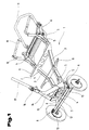
- vehicle substructure 1 is a vehicle substructure 1 or a chassis for a four-wheel, driven Vehicle that is used to transport at least one person.
- this vehicle substructure 1 consists of a main frame 2, which consists of an approximately annular arrangement of closed hollow profiles is executed.
- This main frame 2 is preferably made of two side hollow profiles 3 and two diametrically opposite torsion springs 4 are formed, the axes of rotation the torsion springs 4 are arranged transversely to the direction of travel of the vehicle.
- This design of the main frame 2 with hollow profiles is also a torsionally rigid Construction of the vehicle possible. This is made possible by the fact that each side hollow profile 3 of the main frame 2 with the torsion springs 4 rigid and rigid with each other are connected. This bending and drilling rigidity is achieved in that the Connection is made via preferably flat gusset plates 5.
- the gusset plates 5 are arranged on both sides of the side hollow profiles 3, the weld seam in the neutral level of the main bending stress of the respective connection profiles, in this case the side hollow sections 3. Elongation loads on the weld seam can be avoided for such a case of stress, whereby There are advantages in terms of weld strength.
- the torsion springs 4 A rigid connection axis 7 is provided via the rocker arm 6. The connection axis 7 has at its ends a bearing 8 for the wheels of the vehicle.
- the side hollow sections 3 have receptacles 9 arranged transversely to the direction of travel the fairing of the vehicle. Furthermore, can also on the gusset plates 5 for the rear torsion spring 4 seen in the direction of travel is directed approximately vertically upwards Supports 10 can be arranged for this cladding. Other attachments or support frames 11, even if they protrude beyond the rear torsion spring 4, could by means of Gusset plates 5 are attached to the main frame 2 and / or to the supports 10.
- the connecting axis 7 is in the area between the rocker arms 6 as a soft drill open profile 12 formed.
- a bending and drill resistant reinforcement 13 is provided, so that by Art and way of reinforcement 13 optionally a hollow profile is formed.
- the drilling resistance of the connecting axis 7 varies accordingly.
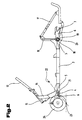
- Control console 14 On the torsion spring 4, viewed in the direction of travel on the front torsion spring 4, there is one Control console 14 arranged for the steering of the vehicle. At this control console 14, which can be made in two parts and each part near the rocker arm 6 is arranged, a head tube 15 is attached to an inner steering tube. On this head tube 15 connects to a link 17 via a connecting member 16.
- the rocker arms 6 are both on the torsion springs 4 provided for the front as well as for the rear connecting axis 7. Furthermore is on the support 10 or on the gusset plate 5 for the rear axis of rotation 4 of the support frame 11, for example for a receiving basket of the vehicle. As well is on the front torsion spring 4, the control console 14 with the head tube 15 and Handlebar 17 arranged.
- the torsion spring 4 consists of two concentrically arranged hollow profiles, the outer hollow profile a torsion spring tube 18 and the inner hollow profile a torsion spring axis 19 is. At least one is between the torsion spring tube 18 and the torsion spring axis 19 Elastomer element 20 arranged.
- the arrangement of these torsion springs 4 is a sufficient longitudinal rigidity in the direction of its axis of rotation and perpendicular in the plane to achieve this.
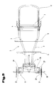
- the rocker arms 6 are rigidly connected to the connecting axis 7. Furthermore are the rocker arms 6 drill soft in their longitudinal axis and have a thin-walled flat shape. As mentioned earlier, does one different Wheel deflection inevitably entangles the connecting axis 7 the vehicle body.
- the rocker arms 6 are therefore carried out softly in its longitudinal axis, so that the necessary axis offset can be executed.
- a fulcrum 21 of the rocker arm 6 lies on the in Driving direction seen front connection axis 7 on the - dash-dotted line - Line of action between the overall center of gravity 22 of the vehicle and one Contact point 23 of the tires 24 of the wheels.
- the main frame 2 consisting of the side hollow profiles 3 and the torsion springs 4, the receptacles 9 for the paneling of the vehicle. about the rear torsion spring 4, seen in the direction of travel, the support frame 11 can also protrude.
- This connecting axis 7 can be cranked, for example for the arrangement of the drive.
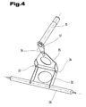
- the front connecting axis 7 is on both sides Bearing 8, in particular in this case with a steering knuckle bearing 25 and Steering structure, which is designed as a cassette construction.
- the steering construction consists essentially of a tie rod 26, each with a ball joint is connected to steering levers 27 arranged on both sides.
- the steering levers 27 are in turn connected to steering knuckles 28 which, via the steering knuckle bearing 25 the connecting axis 7 form a unit. Because the tie rod 26 has a ball joint 29 is connected to the steering levers 27 of the steering knuckle 28 is in a certain Given a pivoting movement of the tie rod 26 about its longitudinal axis.
- Wheel hubs 30 are provided on the steering knuckle 28, wherein these wheel hubs 30 are provided with brake disks 31.
- a tie rod lever 32 is rigidly arranged, in which a swivel joint at the upper end 33, whose axis of rotation 34 is parallel to the tie rod 26, is provided.
- a swivel joint at the upper end 33 whose axis of rotation 34 is parallel to the tie rod 26, is provided.
- an intermediate lever 35 is articulated in the axis of rotation 34 on the tie rod lever 32, which is thus pivotable about an axis parallel to the tie rod 26.
- the intermediate lever 35 is articulated via a crank joint 36 with a steering eccentric 37 which is attached to the head tube 15.
- This steering construction transmits movements of the steering eccentric 37 via the tie rod 26 parallel to it directly on the joints for adjusting the wheels.
- this steering construction can adjust the variable distance of the steering eccentric Compensate 37 perpendicular to the tie rod 26.
Description
Der sich durch die Merkmale des Kennzeichenteiles des Anspruches 1 ergebende überraschende Vorteil ist darin zu sehen, daß mit einer ausgesprochen einfachen Konstruktion eine optimale Radführung erreicht wird, die ein stabiles Fahrverhalten des Fahrzeuges gewährleistet. Durch die Ausbildung des Hauptrahmens mit Hohlprofilen, die biege- und drillsteif miteinander verbunden sind, ist vorteilhafterweise auch der Aufbau des Fahrzeuges äußerst verwindungssteif. Ferner ist durch die Anordnung der Drehfedern der Vorteil gegeben, daß neben dem gutem Materialausnutzungsgrad für das elastische Element der Federung, die Möglichkeit gegeben ist, Funktionen der Radführung mittels dieser Federung auszuführen. Als Radführungselement wird die biegestarre Verbindungsachse vorgesehen. Darüber hinaus wird durch diese biegestarre Verbindungsachse der Vorteil erzielt, daß die Spur- und Sturzveränderung der Räder einer Verbindungsachse weitgehend starr miteinander gekoppelt ist. Dadurch sind Spurweite, Spur- und Sturzwinkel invariant gegenüber der Ebene durch die Berührungspunkte der Räder auf der Aufstandsfläche.
- Fig. 1
- eine Schrägansicht des erfindungsgemäßen Fahrzeugunterbaus;
- Fig. 2
- eine Seitenansicht des erfindungsgemäßen Fahrzeugunterbaus;
- Fig. 3
- eine Draufsicht eines erfindungsgemäßen Fahrzeugunterbaus;
- Fig. 4
- eine Schrägansicht eines Teiles der Lenkkonstruktion des erfindungsgemäßen Fahrzeugunterbaus.
- 1
- Fahrzeugunterbau
- 2
- Hauptrahmen
- 3
- Seitenhohlprofil
- 4
- Drehfeder
- 5
- Knotenblech
- 6
- Schwinghebel
- 7
- Verbindungsachse
- 8
- Lagerung
- 9
- Aufnahme
- 10
- Stütze
- 11
- Tragrahmen
- 12
- Profil
- 13
- Verstärkung
- 14
- Steuerkonsole
- 15
- Steuerrohr
- 16
- Verbindungsglied
- 17
- Lenker
- 18
- Drehfederrohr
- 19
- Drehfederachse
- 20
- Elastomerelement
- 21
- Drehpunkt
- 22
- Gesamtschwerpunkt
- 23
- Aufstandspunkt
- 24
- Reifen
- 25
- Achsschenkellagerung
- 26
- Spurstange
- 27
- Lenkhebel
- 28
- Achsschenkel
- 29
- Kugelgelenk
- 30
- Radnabe
- 31
- Bremsscheibe
- 32
- Spurstangenhebel
- 33
- Drehgelenk
- 34
- Drehachse
- 35
- Zwischenhebel
- 36
- Kurbelgelenk
- 37
- Lenkexzenter
Claims (13)
- Fahrzeugunterbau bzw. Chassis für ein vierräderiges, angetriebenes Fahrzeug zur Beförderung von vorzugsweise mindestens einer Person, wobei ein Hauptrahmen (2) als eine Anordnung von geschlossenen Hohlprofilen ausgeführt ist, dadurch gekennzeichnet, daß der Hauptrahmen (2) aus zwei Seitenhohlprofilen (3) und zwei Drehstabfedern (4) besteht und als etwa ringförmige, biege- und drillsteife Anordnung ausgeführt ist, wobei die Drehstabfedern (4) gegenüberliegend mit quer zur Fahrtrichtung vorgesehener Drehachse angeordnet sind und die Drehstabfedern (4) Außenrohre (18) aufweisen, wobei die Außenrohre (18) mit den Seitenhohlprofilen (3) des Hauptrahmens (2) über Knotenbleche (5) verbunden sind und daß an den Drehstabfedern (4) über Schwinghebel (6) eine biegestarre Verbindungsachse (7), die an ihren Enden für die Räder eine Lagerung (8) aufweist, vorgesehen ist, wobei die Verbindungsachse (7) im Bereich zwischen den, in ihrer Längsachse drillweich ausgeführten, Schwinghebeln (6) als drillweiches Profil ausgeführt ist.
- Fahrzeugunterbau nach Anspruch 1, dadurch gekennzeichnet, daß alle Verbindungen der einzelnen Teile ausschließlich als Schweißnähte ausgeführt sind.
- Fahrzeugunterbau nach Anspruch 1 oder 2, dadurch gekennzeichnet, daß die Drehstabfeder (4) aus zwei konzentrisch angeordneten Hohlprofilen besteht, wobei zwischen den Hohlprofilen, vorzugsweise nur im Bereich der Anordnung des Schwinghebels (6), mindestens ein Elastomerelement (20) vorgesehen ist.
- Fahrzeugunterbau nach einem oder mehreren der vorhergehenden Ansprüche, dadurch gekennzeichnet, daß die Drehstabfeder (4) aus dem Außenrohr (18), dem Elastomerfederelement (20) und der Drehstabfederachse (19) besteht.
- Fahrzeugunterbau nach einem oder mehreren der vorhergehenden Ansprüche, dadurch gekennzeichnet, daß die Verbindung von den Seitenhohlprofilen (3) zu weiteren Anschlußprofilen über beiderseits des Seitenhohlprofils (3) angeordnete, ebene Knotenbleche (5) erfolgt.
- Fahrzeugunterbau nach einem oder mehreren der vorhergehenden Ansprüche, dadurch gekennzeichnet, daß die Verbindungsachse (7) im Bereich zwischen den Schwinghebeln (6) als offenes Profil ausgeführt ist.
- Fahrzeugunterbau nach einem oder mehreren der vorhergehenden Ansprüche, dadurch gekennzeichnet, daß die Verbindungsachse (7) im Bereich zwischen Schwinghebel (6) und Lagerung (8), insbesondere der Achsschenkellagerung (25), eine biege- und drillsteife Verstärkung (13) aufweist.
- Fahrzeugunterbau nach einem oder mehreren der vorhergehenden Ansprüche, dadurch gekennzeichnet, daß die Verbindungsachse (7) im Bereich zwischen Schwinghebel (6) und Lagerung (8), insbesondere der Achsschenkellagerung (25), als Hohlprofil ausgeführt ist.
- Fahrzeugunterbau nach einem oder mehreren der vorhergehenden Ansgrüche, dadurch gekennzeichnet, daß die Schwinghebel (6) starr mit der Verbindungsachse (7) verbunden sind.
- Fahrzeugunterbau nach einem oder mehreren der vorhergehenden Ansprüche, dadurch gekennzeichnet, daß die Schwinghebel (6) eine dünnwandige flache Form aufweisen.
- Fahrzeugunterbau nach einem oder mehreren der vorhergehenden Ansprüche, dadurch gekennzeichnet, daß die Drehachse (21) des Schwinghebels (6) an der in Fahrtrichtung gesehenen vorderen Verbindungsachse (7) auf der Wirkungslinie zwischen Gesamtschwerpunkt (22) des Fahrzeuges und dem Aufstandspunkt (23) der Räder liegt.
- Fahrzeugunterbau nach einem oder mehreren der vorhergehenden Ansprüche, dadurch gekennzeichnet, daß sämtliche Hohlprofile senkrechte Trennschnitte aufweisen.
- Fahrzeugunterbau nach einem oder mehreren der vorhergehenden Ansprüche, dadurch gekennzeichnet, daß ein Lenkgestänge vorgesehen ist, bestehend aus einem starr mit einer Spurstange (26) verbundenen Spurstangenhebel (32) sowie einem über eine zur Spurstange (26) parallele Drehachse (34) am Spurstangenhebel (32) schwenkbaren Zwischenhebel (35), der über ein Kurbelgelenk (36) mit einem Lenkexzenter (37) verbunden ist.
Priority Applications (1)
| Application Number | Priority Date | Filing Date | Title |
|---|---|---|---|
| SI9930213T SI1119462T1 (en) | 1998-10-06 | 1999-10-05 | Vehicle undercarriage |
Applications Claiming Priority (3)
| Application Number | Priority Date | Filing Date | Title |
|---|---|---|---|
| AT0166498A AT410427B (de) | 1998-10-06 | 1998-10-06 | Fahrzeugunterbau |
| AT166498 | 1998-10-06 | ||
| PCT/AT1999/000238 WO2000020237A1 (de) | 1998-10-06 | 1999-10-05 | Fahrzeugunterbau |
Publications (2)
| Publication Number | Publication Date |
|---|---|
| EP1119462A1 EP1119462A1 (de) | 2001-08-01 |
| EP1119462B1 true EP1119462B1 (de) | 2002-12-18 |
Family
ID=3518325
Family Applications (1)
| Application Number | Title | Priority Date | Filing Date |
|---|---|---|---|
| EP99947080A Expired - Lifetime EP1119462B1 (de) | 1998-10-06 | 1999-10-05 | Fahrzeugunterbau |
Country Status (12)
| Country | Link |
|---|---|
| US (1) | US6595534B1 (de) |
| EP (1) | EP1119462B1 (de) |
| JP (1) | JP4570782B2 (de) |
| KR (1) | KR100561139B1 (de) |
| CN (1) | CN1145563C (de) |
| AT (2) | AT410427B (de) |
| AU (1) | AU761507B2 (de) |
| BR (1) | BR9916175A (de) |
| CA (1) | CA2346285C (de) |
| DE (1) | DE59903862D1 (de) |
| ES (1) | ES2189487T3 (de) |
| WO (1) | WO2000020237A1 (de) |
Families Citing this family (8)
| Publication number | Priority date | Publication date | Assignee | Title |
|---|---|---|---|---|
| CN1313310C (zh) * | 2004-11-23 | 2007-05-02 | 张向阳 | 一种微型四轮车转向装置 |
| CN102014760B (zh) * | 2008-06-09 | 2013-11-06 | 韩商未来股份有限公司 | 手术机器人的主动接口和驱动方法 |
| GR1006455B (el) * | 2008-06-25 | 2009-06-22 | Αθανασιου Δημητριος Χατζηκακιδης | Παραμετρικο συστημα πλαισιου για οχηματα σχηματιζομενο απο τεσσερα στοιχεια αναρτησεως με εγκαρσια ραβδο στρεψεως και ομοαξονικο συστημα αποσβεστηρα μεσα σε φατνωμα που επιτρεπει την αποθηκευση κεντρικα βαρεων στοιχειων (οπως μπαταριες) |
| FR3004692B1 (fr) * | 2013-04-17 | 2016-11-04 | Sodikart | Kart a structure modulaire. |
| JP6600260B2 (ja) * | 2016-02-04 | 2019-10-30 | 本田技研工業株式会社 | 4輪車両 |
| CN106364559A (zh) * | 2016-11-09 | 2017-02-01 | 佛山市威思通电动力系统有限公司 | 一种卡丁车车架 |
| CN107244373B (zh) * | 2017-06-22 | 2023-08-22 | 重庆银钢科技(集团)有限公司 | 一种两轮车 |
| CN112690154B (zh) * | 2021-01-18 | 2022-08-12 | 华南农业大学 | 一种温室喷淋系统 |
Family Cites Families (23)
| Publication number | Priority date | Publication date | Assignee | Title |
|---|---|---|---|---|
| US1385611A (en) * | 1919-02-04 | 1921-07-26 | Gangloff Jean | Motor-car |
| BE402119A (de) * | 1932-10-14 | |||
| BE399361A (de) * | 1933-10-30 | |||
| NL76938C (de) * | 1950-03-24 | |||
| NL169167B (nl) * | 1950-09-13 | Martin Marietta Corp | Werkwijze voor de bereiding van calciumaluminaatcementmengsels en hieruit vervaardigde voorwerpen. | |
| FR1158530A (fr) * | 1956-09-05 | 1958-06-16 | Anciens Etablissements Panhard | Infrastructure pour véhicules automobiles |
| GB839226A (en) * | 1958-03-20 | 1960-06-29 | Tom Edgerton Clarke Hirst | Rubber spring suspensions for the road wheels of automobiles |
| FR80906E (fr) * | 1961-12-05 | 1963-07-05 | Anciens Etablissements Panhard | Perfectionnements apportés aux carrosseries de véhicules automobiles |
| DE1630647A1 (de) * | 1967-11-07 | 1971-05-19 | Kober Kg Maschb | Achse fuer Wohnwagen od.dgl. |
| US4261591A (en) * | 1979-06-18 | 1981-04-14 | Warne Jr John P | Fully triangulated, individual wheel suspension system |
| JPS60124512A (ja) * | 1983-12-08 | 1985-07-03 | Toyoda Autom Loom Works Ltd | フォ−クリフトトラックの懸架装置 |
| JPH049257Y2 (de) * | 1985-05-25 | 1992-03-09 | ||
| DE3543929A1 (de) * | 1985-12-12 | 1987-06-19 | Aluminium Walzwerke Singen | Personenkraftwagen |
| DE8619274U1 (de) | 1986-07-18 | 1986-09-18 | Alois Kober KG, 8871 Kötz | Torsionsfederachse für Fahrzeug-Anhänger |
| JPS6370412U (de) * | 1986-10-29 | 1988-05-11 | ||
| DE4110571C2 (de) * | 1990-05-30 | 1995-04-27 | Volkswagen Ag | Kraftfahrzeug-Hinterachse |
| US5215331A (en) | 1991-11-08 | 1993-06-01 | Pittman Jerry W | Structural member for a trailer chassis frame |
| JP2949986B2 (ja) * | 1991-12-27 | 1999-09-20 | 三菱自動車工業株式会社 | 自動車用キャスタ角制御装置 |
| DE4447971B4 (de) * | 1994-05-13 | 2007-03-29 | GM Global Technology Operations, Inc., Detroit | Kraftfahrzeug-Hinterachse |
| DE4444850A1 (de) * | 1994-12-16 | 1996-06-20 | Bernd Katthoefer | Kartrahmen mit verbesserten Federungs- und Dämpfungseigenschaften sowie gezielter Fahrwerksgeometrie-Einstellbarheit |
| US5816606A (en) | 1995-10-05 | 1998-10-06 | Chrysler Corporation | Horizontally-mounted rear shock absorber for lightweight motor vehicle |
| GB2306139B (en) * | 1995-10-11 | 1999-05-26 | Terrapid Technologies Cc | A vehicle |
| GB9618869D0 (en) * | 1996-09-10 | 1996-10-23 | Bardley Doublelock Ltd | Vehicle |
-
1998
- 1998-10-06 AT AT0166498A patent/AT410427B/de not_active IP Right Cessation
-
1999
- 1999-10-05 ES ES99947080T patent/ES2189487T3/es not_active Expired - Lifetime
- 1999-10-05 CA CA002346285A patent/CA2346285C/en not_active Expired - Fee Related
- 1999-10-05 WO PCT/AT1999/000238 patent/WO2000020237A1/de active IP Right Grant
- 1999-10-05 BR BR9916175-3A patent/BR9916175A/pt not_active IP Right Cessation
- 1999-10-05 US US09/821,461 patent/US6595534B1/en not_active Expired - Fee Related
- 1999-10-05 KR KR1020017004410A patent/KR100561139B1/ko not_active IP Right Cessation
- 1999-10-05 DE DE59903862T patent/DE59903862D1/de not_active Expired - Lifetime
- 1999-10-05 JP JP2000573573A patent/JP4570782B2/ja not_active Expired - Fee Related
- 1999-10-05 AU AU60673/99A patent/AU761507B2/en not_active Ceased
- 1999-10-05 CN CNB998118532A patent/CN1145563C/zh not_active Expired - Fee Related
- 1999-10-05 AT AT99947080T patent/ATE229890T1/de active
- 1999-10-05 EP EP99947080A patent/EP1119462B1/de not_active Expired - Lifetime
Also Published As
| Publication number | Publication date |
|---|---|
| CA2346285A1 (en) | 2000-04-13 |
| AT410427B (de) | 2003-04-25 |
| ATE229890T1 (de) | 2003-01-15 |
| KR20010080038A (ko) | 2001-08-22 |
| CN1145563C (zh) | 2004-04-14 |
| AU6067399A (en) | 2000-04-26 |
| AU761507B2 (en) | 2003-06-05 |
| EP1119462A1 (de) | 2001-08-01 |
| US6595534B1 (en) | 2003-07-22 |
| JP4570782B2 (ja) | 2010-10-27 |
| DE59903862D1 (de) | 2003-01-30 |
| CA2346285C (en) | 2009-01-06 |
| JP2002526312A (ja) | 2002-08-20 |
| BR9916175A (pt) | 2001-08-14 |
| WO2000020237A1 (de) | 2000-04-13 |
| ATA166498A (de) | 2002-09-15 |
| ES2189487T3 (es) | 2003-07-01 |
| CN1322171A (zh) | 2001-11-14 |
| KR100561139B1 (ko) | 2006-03-15 |
Similar Documents
| Publication | Publication Date | Title |
|---|---|---|
| EP0193089B1 (de) | Hinterradaufhängung für Kraftfahrzeuge, insbesondere für angetriebene Hinterräder | |
| DE4340557C2 (de) | Radaufhängung | |
| DE19521875C2 (de) | Achsaufhängung für Starrachsen in Fahrzeugen | |
| DE102007055353B4 (de) | Verbundlenkerachse | |
| DE102006044151A1 (de) | Einzelradaufhängung vom Doppelquerlenker-Typ | |
| DE3738964C1 (de) | Unabhaengige Radaufhaengung fuer Kraftfahrzeuge | |
| DE3331282A1 (de) | Radaufhaengung fuer lenkbare vorderraeder von kraftfahrzeugen | |
| DE602005002921T2 (de) | Achsaufhängungsvorrichtung | |
| DE3507141C2 (de) | ||
| EP1958797B1 (de) | Radaufhängung für die gelenkten Räder eines Kraftfahrzeuges | |
| DE19605283A1 (de) | Längslenkeraufhängung für Fahrzeuge | |
| EP2435263B1 (de) | Fahrzeug-einzelradaufhängung | |
| EP0873891B1 (de) | Einzelradaufhängung für gelenkte Räder von Kraftfahrzeugen, insbesondere Personenkraftwagen | |
| EP1119462B1 (de) | Fahrzeugunterbau | |
| DE3718137C2 (de) | ||
| DE60315541T2 (de) | Befestigungsaufbau für einen Radträger eines Kraftfahrzeugs | |
| DE4015974A1 (de) | Lenkbare kraftfahrzeug-hinterachse | |
| DE4021157A1 (de) | Einzelradaufhaengung fuer kraftfahrzeuge | |
| DE2220072A1 (de) | Radaufhaengung | |
| DE4030819C2 (de) | Hinterradaufhängung für ein vierradgelenktes Fahrzeug | |
| DE3329686C2 (de) | Spurweitenkonstante Achsaufhängung, insbesondere Hinterachsaufhängung, für Kraftfahrzeuge | |
| DE4206896C2 (de) | Radaufhängung für lenkbare Räder von Kraftfahrzeugen | |
| EP3319821A2 (de) | Doppelquerlenkerachse | |
| DE19756059C2 (de) | Führungsvorrichtung für eine Kraftfahrzeugstarrachse | |
| DE10007662C1 (de) | Unabhängige Radaufhängung, insbesondere Vorderradaufhängung in Kraftfahrzeuge |
Legal Events
| Date | Code | Title | Description |
|---|---|---|---|
| PUAI | Public reference made under article 153(3) epc to a published international application that has entered the european phase |
Free format text: ORIGINAL CODE: 0009012 |
|
| 17P | Request for examination filed |
Effective date: 20010402 |
|
| AK | Designated contracting states |
Kind code of ref document: A1 Designated state(s): AT BE CH CY DE DK ES FI FR GB GR IE IT LI LU MC NL PT SE |
|
| AX | Request for extension of the european patent |
Free format text: AL;LT;LV;MK;RO PAYMENT 20010402;SI PAYMENT 20010402 |
|
| GRAG | Despatch of communication of intention to grant |
Free format text: ORIGINAL CODE: EPIDOS AGRA |
|
| 17Q | First examination report despatched |
Effective date: 20020208 |
|
| GRAG | Despatch of communication of intention to grant |
Free format text: ORIGINAL CODE: EPIDOS AGRA |
|
| GRAH | Despatch of communication of intention to grant a patent |
Free format text: ORIGINAL CODE: EPIDOS IGRA |
|
| GRAH | Despatch of communication of intention to grant a patent |
Free format text: ORIGINAL CODE: EPIDOS IGRA |
|
| GRAA | (expected) grant |
Free format text: ORIGINAL CODE: 0009210 |
|
| AK | Designated contracting states |
Kind code of ref document: B1 Designated state(s): AT BE CH CY DE DK ES FI FR GB GR IE IT LI LU MC NL PT SE |
|
| AX | Request for extension of the european patent |
Free format text: RO PAYMENT 20010402;SI PAYMENT 20010402 |
|
| PG25 | Lapsed in a contracting state [announced via postgrant information from national office to epo] |
Ref country code: IE Free format text: LAPSE BECAUSE OF FAILURE TO SUBMIT A TRANSLATION OF THE DESCRIPTION OR TO PAY THE FEE WITHIN THE PRESCRIBED TIME-LIMIT Effective date: 20021218 Ref country code: GR Free format text: LAPSE BECAUSE OF FAILURE TO SUBMIT A TRANSLATION OF THE DESCRIPTION OR TO PAY THE FEE WITHIN THE PRESCRIBED TIME-LIMIT Effective date: 20021218 Ref country code: FI Free format text: LAPSE BECAUSE OF FAILURE TO SUBMIT A TRANSLATION OF THE DESCRIPTION OR TO PAY THE FEE WITHIN THE PRESCRIBED TIME-LIMIT Effective date: 20021218 |
|
| REF | Corresponds to: |
Ref document number: 229890 Country of ref document: AT Date of ref document: 20030115 Kind code of ref document: T |
|
| REG | Reference to a national code |
Ref country code: GB Ref legal event code: FG4D Free format text: NOT ENGLISH |
|
| REG | Reference to a national code |
Ref country code: CH Ref legal event code: EP |
|
| REG | Reference to a national code |
Ref country code: IE Ref legal event code: FG4D Free format text: GERMAN |
|
| REF | Corresponds to: |
Ref document number: 59903862 Country of ref document: DE Date of ref document: 20030130 Kind code of ref document: P |
|
| PG25 | Lapsed in a contracting state [announced via postgrant information from national office to epo] |
Ref country code: SE Free format text: LAPSE BECAUSE OF FAILURE TO SUBMIT A TRANSLATION OF THE DESCRIPTION OR TO PAY THE FEE WITHIN THE PRESCRIBED TIME-LIMIT Effective date: 20030318 Ref country code: DK Free format text: LAPSE BECAUSE OF FAILURE TO SUBMIT A TRANSLATION OF THE DESCRIPTION OR TO PAY THE FEE WITHIN THE PRESCRIBED TIME-LIMIT Effective date: 20030318 |
|
| LTIE | Lt: invalidation of european patent or patent extension |
Effective date: 20021218 |
|
| GBT | Gb: translation of ep patent filed (gb section 77(6)(a)/1977) |
Effective date: 20030515 |
|
| REG | Reference to a national code |
Ref country code: ES Ref legal event code: FG2A Ref document number: 2189487 Country of ref document: ES Kind code of ref document: T3 |
|
| ET | Fr: translation filed | ||
| REG | Reference to a national code |
Ref country code: IE Ref legal event code: FD4D Ref document number: 1119462E Country of ref document: IE |
|
| PG25 | Lapsed in a contracting state [announced via postgrant information from national office to epo] |
Ref country code: CY Free format text: LAPSE BECAUSE OF FAILURE TO SUBMIT A TRANSLATION OF THE DESCRIPTION OR TO PAY THE FEE WITHIN THE PRESCRIBED TIME-LIMIT Effective date: 20031005 |
|
| PLBE | No opposition filed within time limit |
Free format text: ORIGINAL CODE: 0009261 |
|
| STAA | Information on the status of an ep patent application or granted ep patent |
Free format text: STATUS: NO OPPOSITION FILED WITHIN TIME LIMIT |
|
| PG25 | Lapsed in a contracting state [announced via postgrant information from national office to epo] |
Ref country code: MC Free format text: LAPSE BECAUSE OF NON-PAYMENT OF DUE FEES Effective date: 20031031 Ref country code: BE Free format text: LAPSE BECAUSE OF NON-PAYMENT OF DUE FEES Effective date: 20031031 |
|
| 26N | No opposition filed |
Effective date: 20030919 |
|
| BERE | Be: lapsed |
Owner name: *WACHAUER OSKAR Effective date: 20031031 |
|
| REG | Reference to a national code |
Ref country code: SI Ref legal event code: IF |
|
| PGFP | Annual fee paid to national office [announced via postgrant information from national office to epo] |
Ref country code: PT Payment date: 20120301 Year of fee payment: 13 |
|
| PGFP | Annual fee paid to national office [announced via postgrant information from national office to epo] |
Ref country code: AT Payment date: 20120424 Year of fee payment: 13 |
|
| REG | Reference to a national code |
Ref country code: PT Ref legal event code: MM4A Free format text: LAPSE DUE TO NON-PAYMENT OF FEES Effective date: 20130405 |
|
| PGFP | Annual fee paid to national office [announced via postgrant information from national office to epo] |
Ref country code: ES Payment date: 20120224 Year of fee payment: 13 |
|
| REG | Reference to a national code |
Ref country code: SI Ref legal event code: KO00 Effective date: 20130516 |
|
| PGFP | Annual fee paid to national office [announced via postgrant information from national office to epo] |
Ref country code: DE Payment date: 20130429 Year of fee payment: 14 Ref country code: CH Payment date: 20130424 Year of fee payment: 14 Ref country code: GB Payment date: 20130429 Year of fee payment: 14 Ref country code: LU Payment date: 20130502 Year of fee payment: 14 |
|
| PG25 | Lapsed in a contracting state [announced via postgrant information from national office to epo] |
Ref country code: PT Free format text: LAPSE BECAUSE OF NON-PAYMENT OF DUE FEES Effective date: 20130405 |
|
| PGFP | Annual fee paid to national office [announced via postgrant information from national office to epo] |
Ref country code: IT Payment date: 20130430 Year of fee payment: 14 Ref country code: NL Payment date: 20130429 Year of fee payment: 14 Ref country code: FR Payment date: 20130610 Year of fee payment: 14 |
|
| REG | Reference to a national code |
Ref country code: NL Ref legal event code: V1 Effective date: 20140501 |
|
| REG | Reference to a national code |
Ref country code: CH Ref legal event code: PL |
|
| REG | Reference to a national code |
Ref country code: AT Ref legal event code: MM01 Ref document number: 229890 Country of ref document: AT Kind code of ref document: T Effective date: 20131005 |
|
| GBPC | Gb: european patent ceased through non-payment of renewal fee |
Effective date: 20131005 |
|
| REG | Reference to a national code |
Ref country code: DE Ref legal event code: R119 Ref document number: 59903862 Country of ref document: DE Effective date: 20140501 |
|
| PG25 | Lapsed in a contracting state [announced via postgrant information from national office to epo] |
Ref country code: CH Free format text: LAPSE BECAUSE OF NON-PAYMENT OF DUE FEES Effective date: 20131031 Ref country code: LI Free format text: LAPSE BECAUSE OF NON-PAYMENT OF DUE FEES Effective date: 20131031 Ref country code: GB Free format text: LAPSE BECAUSE OF NON-PAYMENT OF DUE FEES Effective date: 20131005 |
|
| REG | Reference to a national code |
Ref country code: FR Ref legal event code: ST Effective date: 20140630 |
|
| PG25 | Lapsed in a contracting state [announced via postgrant information from national office to epo] |
Ref country code: NL Free format text: LAPSE BECAUSE OF NON-PAYMENT OF DUE FEES Effective date: 20140501 Ref country code: DE Free format text: LAPSE BECAUSE OF NON-PAYMENT OF DUE FEES Effective date: 20140501 Ref country code: FR Free format text: LAPSE BECAUSE OF NON-PAYMENT OF DUE FEES Effective date: 20131031 Ref country code: IT Free format text: LAPSE BECAUSE OF NON-PAYMENT OF DUE FEES Effective date: 20131005 Ref country code: AT Free format text: LAPSE BECAUSE OF NON-PAYMENT OF DUE FEES Effective date: 20131005 |
|
| REG | Reference to a national code |
Ref country code: ES Ref legal event code: FD2A Effective date: 20150504 |
|
| PG25 | Lapsed in a contracting state [announced via postgrant information from national office to epo] |
Ref country code: ES Free format text: LAPSE BECAUSE OF NON-PAYMENT OF DUE FEES Effective date: 20131006 |
|
| PG25 | Lapsed in a contracting state [announced via postgrant information from national office to epo] |
Ref country code: LU Free format text: THE PATENT HAS BEEN ANNULLED BY A DECISION OF A NATIONAL AUTHORITY Effective date: 20121005 |