EP1118740A2 - Antrieb für einen an einem ortsfesten Rahmen drehbar gelagerten Flügel eines Fenster, einer Tür oder dergleichen - Google Patents
Antrieb für einen an einem ortsfesten Rahmen drehbar gelagerten Flügel eines Fenster, einer Tür oder dergleichen Download PDFInfo
- Publication number
- EP1118740A2 EP1118740A2 EP01100861A EP01100861A EP1118740A2 EP 1118740 A2 EP1118740 A2 EP 1118740A2 EP 01100861 A EP01100861 A EP 01100861A EP 01100861 A EP01100861 A EP 01100861A EP 1118740 A2 EP1118740 A2 EP 1118740A2
- Authority
- EP
- European Patent Office
- Prior art keywords
- wing
- bearing
- axis
- bracket
- drive
- Prior art date
- Legal status (The legal status is an assumption and is not a legal conclusion. Google has not performed a legal analysis and makes no representation as to the accuracy of the status listed.)
- Granted
Links
- 238000005452 bending Methods 0.000 description 8
- 230000007423 decrease Effects 0.000 description 1
- 238000009434 installation Methods 0.000 description 1
- 238000005457 optimization Methods 0.000 description 1
- 238000010008 shearing Methods 0.000 description 1
- 230000006641 stabilisation Effects 0.000 description 1
- 238000011105 stabilization Methods 0.000 description 1
Images


Classifications
-
- E—FIXED CONSTRUCTIONS
- E05—LOCKS; KEYS; WINDOW OR DOOR FITTINGS; SAFES
- E05F—DEVICES FOR MOVING WINGS INTO OPEN OR CLOSED POSITION; CHECKS FOR WINGS; WING FITTINGS NOT OTHERWISE PROVIDED FOR, CONCERNED WITH THE FUNCTIONING OF THE WING
- E05F15/00—Power-operated mechanisms for wings
- E05F15/60—Power-operated mechanisms for wings using electrical actuators
- E05F15/603—Power-operated mechanisms for wings using electrical actuators using rotary electromotors
- E05F15/611—Power-operated mechanisms for wings using electrical actuators using rotary electromotors for swinging wings
- E05F15/616—Power-operated mechanisms for wings using electrical actuators using rotary electromotors for swinging wings operated by push-pull mechanisms
- E05F15/619—Power-operated mechanisms for wings using electrical actuators using rotary electromotors for swinging wings operated by push-pull mechanisms using flexible or rigid rack-and-pinion arrangements
-
- E—FIXED CONSTRUCTIONS
- E05—LOCKS; KEYS; WINDOW OR DOOR FITTINGS; SAFES
- E05F—DEVICES FOR MOVING WINGS INTO OPEN OR CLOSED POSITION; CHECKS FOR WINGS; WING FITTINGS NOT OTHERWISE PROVIDED FOR, CONCERNED WITH THE FUNCTIONING OF THE WING
- E05F15/00—Power-operated mechanisms for wings
- E05F15/60—Power-operated mechanisms for wings using electrical actuators
- E05F15/603—Power-operated mechanisms for wings using electrical actuators using rotary electromotors
- E05F15/611—Power-operated mechanisms for wings using electrical actuators using rotary electromotors for swinging wings
- E05F15/63—Power-operated mechanisms for wings using electrical actuators using rotary electromotors for swinging wings operated by swinging arms
-
- E—FIXED CONSTRUCTIONS
- E05—LOCKS; KEYS; WINDOW OR DOOR FITTINGS; SAFES
- E05Y—INDEXING SCHEME ASSOCIATED WITH SUBCLASSES E05D AND E05F, RELATING TO CONSTRUCTION ELEMENTS, ELECTRIC CONTROL, POWER SUPPLY, POWER SIGNAL OR TRANSMISSION, USER INTERFACES, MOUNTING OR COUPLING, DETAILS, ACCESSORIES, AUXILIARY OPERATIONS NOT OTHERWISE PROVIDED FOR, APPLICATION THEREOF
- E05Y2201/00—Constructional elements; Accessories therefor
- E05Y2201/60—Suspension or transmission members; Accessories therefor
- E05Y2201/622—Suspension or transmission members elements
- E05Y2201/644—Flexible elongated pulling elements
- E05Y2201/656—Chains
-
- E—FIXED CONSTRUCTIONS
- E05—LOCKS; KEYS; WINDOW OR DOOR FITTINGS; SAFES
- E05Y—INDEXING SCHEME ASSOCIATED WITH SUBCLASSES E05D AND E05F, RELATING TO CONSTRUCTION ELEMENTS, ELECTRIC CONTROL, POWER SUPPLY, POWER SIGNAL OR TRANSMISSION, USER INTERFACES, MOUNTING OR COUPLING, DETAILS, ACCESSORIES, AUXILIARY OPERATIONS NOT OTHERWISE PROVIDED FOR, APPLICATION THEREOF
- E05Y2201/00—Constructional elements; Accessories therefor
- E05Y2201/60—Suspension or transmission members; Accessories therefor
- E05Y2201/622—Suspension or transmission members elements
- E05Y2201/71—Toothed gearing
- E05Y2201/722—Racks
- E05Y2201/724—Flexible
-
- E—FIXED CONSTRUCTIONS
- E05—LOCKS; KEYS; WINDOW OR DOOR FITTINGS; SAFES
- E05Y—INDEXING SCHEME ASSOCIATED WITH SUBCLASSES E05D AND E05F, RELATING TO CONSTRUCTION ELEMENTS, ELECTRIC CONTROL, POWER SUPPLY, POWER SIGNAL OR TRANSMISSION, USER INTERFACES, MOUNTING OR COUPLING, DETAILS, ACCESSORIES, AUXILIARY OPERATIONS NOT OTHERWISE PROVIDED FOR, APPLICATION THEREOF
- E05Y2900/00—Application of doors, windows, wings or fittings thereof
- E05Y2900/10—Application of doors, windows, wings or fittings thereof for buildings or parts thereof
- E05Y2900/13—Type of wing
- E05Y2900/132—Doors
-
- E—FIXED CONSTRUCTIONS
- E05—LOCKS; KEYS; WINDOW OR DOOR FITTINGS; SAFES
- E05Y—INDEXING SCHEME ASSOCIATED WITH SUBCLASSES E05D AND E05F, RELATING TO CONSTRUCTION ELEMENTS, ELECTRIC CONTROL, POWER SUPPLY, POWER SIGNAL OR TRANSMISSION, USER INTERFACES, MOUNTING OR COUPLING, DETAILS, ACCESSORIES, AUXILIARY OPERATIONS NOT OTHERWISE PROVIDED FOR, APPLICATION THEREOF
- E05Y2900/00—Application of doors, windows, wings or fittings thereof
- E05Y2900/10—Application of doors, windows, wings or fittings thereof for buildings or parts thereof
- E05Y2900/13—Type of wing
- E05Y2900/148—Windows
Definitions
- the invention relates to a drive for a rotatable on a stationary frame mounted wing of a window, door or the like with the features the preamble of claim 1.
- Such a drive is e.g. known from DE 298 17 563 U1.
- the drive is a so-called chain drive, i.e. a drive with thrust output link, which is designed as a chain.
- Such drives are often used for motorized opening and closing of window sashes, e.g. on bottom-hung and top-hung sashes, but also on rotating sashes.
- the chain closes when the sash is open is heavily used for bending or in contact with the closing edge of the wing is coming.
- a certain amount of compensation can be achieved by:
- Drive housing is pivotally mounted on the frame. Nevertheless it turns out in the area of the wing console, especially with small wing dimensions and large opening widths, a collision of the chain at the closing edge of the wing.
- the invention has for its object a drive of the aforementioned To create the kind of wing with different wing dimensions in one large area can be used and in which the thrust output member as little as possible is stressed on bending.
- the console is at a distance from which the free end of the thrust output member Receiving bearing arranged joint, there is no or only less bending stress of the thrust output member, even with relatively small wings and relatively large opening widths.
- Another optimization is obtained when the drive housing is articulated, preferably pivotable with an axis parallel to the axis of rotation of the wing. Through the Swiveling movement of the drive housing when opening the sash results, that the bending stress of the thrust output member is further reduced. In particular in this case, even with small wing dimensions A drive with a rigid push rod output link, even for large opening widths be used.
- the console has a spring which in the Area of the hinge connecting the console sections acts that the console from a mutually extended position, which the console sections in Take the closed position of the wing, in a shear position that pushes the Take the console sections in the open position of the wing.
- This spring stabilizes the angular position of the console sections to each other when actuated the window and also provides vibration protection in the event of wind.
- the joint is one Stop which has the angular shear position with each other over the joint connected console sections limited.
- the console sections are in Open position of the wing at this stop, preferably in mutual Stop, and thus receive a stabilization against further shearing together the console sections.
- the exemplary embodiment shown in FIGS. 1 and 2 is a window with a tilting sash 1, which can be opened and closed by a motor via a chain drive 2.
- the tilting wing 1 is rotatably supported in the area of its lower horizontal edge in tilting belts 3.
- the drive 2 has a drive housing 4 which is mounted on the upper horizontal spar 5 of the fixed frame.
- a drive motor (not shown in detail) is arranged in the drive housing 4 and has a chain 6 as the thrust output link, which chain can be linearly extended and retracted from the drive housing 4. It is a chain drive with a conventional structure, as is known for example from DE 298 17 563 U1.
- the free end of the chain 6 acting as a thrust output link is supported on a bracket 7 mounted in the region of the upper horizontal edge of the wing 1.
- the chain 6 is supported in an articulated manner in a bearing 8 arranged at the free end of the bracket 7.
- the bearing 8 receives the chain end piece 6a in an articulated manner.
- the bearing 8 has a horizontal axis of rotation 8a as the bearing axis.
- the bracket 7 is screwed with its wing-side fastening end 9 to the outside of the wing 1 in the region of the upper horizontal edge of the wing 1.
- the bracket 7 has a joint 10 between the wing-side fastening end 9 and the bearing 8.
- the hinge axis 10a is parallel to the axis of rotation 3a of the wing 1, in the embodiment shown the hinge axis 10 is horizontal and parallel to the upper horizontal edge of the wing 1.
- the hinge axis 10a is relatively close to the fastening end 9 of the bracket.
- the distance of the hinge axis 10a to this fastening end 9 or to the wing plane is, in the exemplary embodiment in FIG. 1, significantly less than the distance from the hinge axis 10a to the bearing 8 or to the horizontal hinge axis of the bearing 8.
- the hinge axis 10a thus divides the bracket 7 into a wing-side bracket section and a console section remote from wing 1.
- a torsion spring 10c concentrically arranged around the hinge axis 10a, which is supported at one end on the wing-side bracket section and at the other end on the bracket section remote from the wing 1, that is to say it rests on one end from the wing-side bracket section between the hinge axis 10a and the fastening end 9 and with its other end on the wing-distant bracket section between the hinge axis 10a and the bearing 8.
- This torsion spring 10c acts on the two console sections in a mutually angular position, as the console 7 assumes when the wing 1 is open. In the closed position, which is shown in FIG.
- the console sections assume an essentially extended position against the action of the torsion spring 10c, in which, in the exemplary embodiment shown, the console sections each extend approximately horizontally in alignment with one another.
- the angle ⁇ between the two console sections is therefore 180 ° in the closed position and decreases continuously when the window 1 is opened.
- the two bracket sections form the legs of the angle a and the bearing axis 10a the apex of the angle ⁇ .
- the angle ⁇ is open to the chain 6.
- the console 7 has a stop in the region of the joint 10, which stop is designed in this way is that the two console sections in the open position of the wing 1 in mutual stop to each other.
- the torsion spring 10c acts on the Console sections in this stop position.
- the horizontal cantilevered length of the console 7, in the position that the console 7 occupies in the closed position of the wing 1, is as large as the horizontally cantilevered extension of the frame 7 immediately above the fixed frame 5 mounted drive housing 4 including a chain end section 6a which projects from the drive housing 4 in the closed position of the wing 1 and is connected to the bearing 8.
- the chain 6 emerges from the drive housing 4 in an essentially horizontal direction of thrust.
- the chain 6 is arranged so that the connecting joints of the chain links are directed essentially vertically.
- the chain 6 is curved in an arc around the wing axis 3a. This means that the axes of the connecting links of the chain links are inclined at an angle to the vertical with a large opening range.
- the drive housing 4 can also have a pivot bearing with which it is mounted on the fixed frame 5.
- the pivot bearing then has an axis of rotation, which is arranged parallel to the axis of rotation 3a of the wing 1, in the case of a tilting window, the axis of rotation of the pivot bearing of the drive housing 4 is then also arranged horizontally.
- a push rod drive can also be used instead of a chain drive, ie a drive in which the thrust output member, which can be moved in and out of the housing 4 , is designed as a rigid push rod.
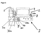
- the drive housing 4 is fastened to the stationary frame 5 via a pivot bearing 30 which, as described above, has a horizontal axis of rotation 30a arranged parallel to the axis of rotation 3a.
- the bearing 8, in which the chain end piece 6a is articulated is designed as a separate component which can be mounted on the bracket 7 in different positions, with a different distance from the bearing axis in each case 8a to the hinge axis 10a.
- the console 7 has three fastening points in this area, which are arranged in a grid-like manner next to one another and in which the bearing 8 can be attached in each case.
- the bearing 8 is arranged in a position in which the distance to the hinge axis 10 is greatest. Two further fastening positions are also possible, in which the distance to the joint axis 10a is reduced step by step.
Landscapes
- Power-Operated Mechanisms For Wings (AREA)
- Hinges (AREA)
- Window Of Vehicle (AREA)
Abstract
Description
- Figur 1
- eine schematische Seitenansicht eines Kippfensterflügels mit einem Kettenantrieb, in Öffnungsstellung des Flügels;
- Figur 2
- eine Seitenansicht in Figur 1, jedoch in Schließstellung des Fensterflügels, Detaildarstellung im oberen Bereich des Fensters mit dem Kettenantrieb;
- Figur 3
- eine Figur 2 entsprechende Seitenansicht eines weiteren Ausführungsbeispiels, bei dem das Lager der Kette auf der Konsole in variablen Positionen einstellbar ist.
- 1
- Kippflügel
- 2
- Kettenantrieb
- 3
- Kippbänder
- 3a
- Flügelachse
- 4
- Antriebsgehäuse
- 5
- horizontaler Holm
- 6
- Kette
- 6a
- Kettenendstück
- 7
- Konsole
- 8
- Lager
- 8a
- horizontale Drehachse
- 9
- Befestigungsende
- 10
- Gelenk
- 10a
- Gelenkachse
- 10c
- Drehfeder
- 30
- Schwenklager
- 30a
- horizontale Drehachse
Claims (12)
- Antrieb (2) für einen an einem ortsfesten Rahmen (5) drehbar gelagerten Flügel (1) eines Fensters, einer Tür oder dergleichen,
mit einem Antriebsgehäuse (4) mit darin angeordnetem elektrischen Motor, und
mit einem vorzugsweise als Kette (6) ausgebildeten Schubabtriebsglied, welches aus dem Antriebsgehäuse (4) aus- und einfahrbar ist,
wobei das Antriebsgehäuse (4) an dem ortsfesten Rahmen (5) montierbar ist und
wobei das freie Ende des Schubabtriebsglieds (6) an einer am Flügel (1) montierbaren Konsole (7) in einem Lager (8) gelenkig gelagert ist,
dadurch gekennzeichnet,
dass die Konsole (7) ein mit Abstand zu dem Lager (8) des Schubabtriebsglieds (6) angeordnetes Gelenk (10) aufweist. - Antrieb nach Anspruch 1,
dadurch gekennzeichnet, dass die Gelenkachse (10a) des Gelenks (10) parallel zur Drehachse (3a) des Flügels (1) angeordnet ist. - Antrieb nach Anspruch 1,
dadurch gekennzeichnet, dass die Gelenkachse (10a) des Gelenks (10) zwischen dem flügelseitigen Befestigungsende (9) der Konsole (7) und dem Lager (8) des Schubabtriebsglieds (6) angeordnet ist. - Antrieb nach Anspruch 1,
dadurch gekennzeichnet, dass der Abstand der Gelenkachse (10a) von der Lagerachse (8a) des Lagers (8) des Schubabtriebsglieds (6) größer ist als der Abstand der Gelenkachse (10a) von dem Befestigungsende (9) der Konsole (7), vorzugsweise um Faktor 5 bis 10 mal so groß. - Antrieb nach Anspruch 1,
dadurch gekennzeichnet, dass im Bereich des Gelenks (10) eine Feder (10c) einwirkt, die die über das Gelenk (10) verbundenen Konsolenabschnitte aus einer mehr oder weniger gestreckten Stellung, die diese in Schließstellung des Fensters (1) einnehmen, in eine Scherstellung drängt, die diese in Öffnungsstellung des Flügels (1) einnehmen. - Antrieb nach Anspruch 5,
dadurch gekennzeichnet, dass die Feder als Drehfeder, vorzugsweise als Schraubendrehfeder (10c), ausgebildet ist, die sich mit ihrem einen Ende an einem dem Flügel (1) zugewandten Konsolenabschnitt und mit ihrem anderen Ende an einem vom Flügel (1) abgewandten Konsolenabschnitt abstützt. - Antrieb nach Anspruch 1,
dadurch gekennzeichnet, dass das Gelenk (10) einen Anschlag aufweist, der die winkelige Stellung der über das Gelenk (10) miteinander verbundenen Konsolenabschnitte begrenzt. - Antrieb nach einem der Ansprüche 5 bis 7,
dadurch gekennzeichnet, dass die Feder (10c) die über das Gelenk (10) miteinander verbundenen Konsolenabschnitte in ihre Anschlaglage, bei der sie im gegenseitigen Anschlag stehen, drängt. - Antrieb nach Anspruch 1,
dadurch gekennzeichnet, dass der Abstand der Lagerachse (8a) des Lagers (8) des Schubabtriebsglieds (6) zur Gelenkachse (10a) des Gelenks (10) variabel einstellbar ist, vorzugsweise stufenlos variabel einstellbar oder schrittweise variabel einstellbar. - Antrieb nach Anspruch 1,
dadurch gekennzeichnet, dass das Lager (8) als separates Bauteil ausgebildet ist, das an oder auf der Konsole (7) anbringbar ist, vorzugsweise variabel anbringbar ist. - Antrieb nach Anspruch 10,
dadurch gekennzeichnet, dass mehrere Befestigungsstellen, vorzugsweise in Rasteranordnung, an oder auf der Konsole (7) angeordnet sind zur Aufnahme des Lagers (8) des Schubabtriebsglieds (6). - Antrieb nach Anspruch 1,
dadurch gekennzeichnet, dass das Antriebsgehäuse (4) an dem ortsfesten Rahmen (5) gelenkig montierbar ist, vorzugsweise um eine zur Drehachse (3a) des Flügels (1) parallelen Achse (30a).
Applications Claiming Priority (2)
| Application Number | Priority Date | Filing Date | Title |
|---|---|---|---|
| DE10002532 | 2000-01-21 | ||
| DE10002532A DE10002532B4 (de) | 2000-01-21 | 2000-01-21 | Antrieb für einen an einem ortsfesten Rahmen drehbar gelagerten Flügel eines Fensters, einer Tür oder dergleichen |
Publications (3)
| Publication Number | Publication Date |
|---|---|
| EP1118740A2 true EP1118740A2 (de) | 2001-07-25 |
| EP1118740A3 EP1118740A3 (de) | 2004-01-21 |
| EP1118740B1 EP1118740B1 (de) | 2007-02-28 |
Family
ID=7628289
Family Applications (1)
| Application Number | Title | Priority Date | Filing Date |
|---|---|---|---|
| EP01100861A Expired - Lifetime EP1118740B1 (de) | 2000-01-21 | 2001-01-16 | Antrieb für einen an einem ortsfesten Rahmen drehbar gelagerten Flügel eines Fenster, einer Tür oder dergleichen |
Country Status (4)
| Country | Link |
|---|---|
| EP (1) | EP1118740B1 (de) |
| AT (1) | ATE355439T1 (de) |
| DE (2) | DE10002532B4 (de) |
| DK (1) | DK1118740T3 (de) |
Cited By (1)
| Publication number | Priority date | Publication date | Assignee | Title |
|---|---|---|---|---|
| DE202012104880U1 (de) * | 2012-12-14 | 2014-03-17 | SCHÜCO International KG | Antriebseinrichtung für einen Flügel eines Fensters oder einer Tür |
Families Citing this family (2)
| Publication number | Priority date | Publication date | Assignee | Title |
|---|---|---|---|---|
| DE102005000141A1 (de) | 2005-10-18 | 2007-04-19 | Siegenia-Aubi Kg | Motorischer Antrieb |
| DE202007000531U1 (de) * | 2007-01-09 | 2007-03-15 | Siegenia-Aubi Kg | Motorischer Antrieb |
Citations (1)
| Publication number | Priority date | Publication date | Assignee | Title |
|---|---|---|---|---|
| DE29817563U1 (de) | 1998-10-01 | 1999-01-28 | D + H Mechatronic, Dingfelder + Kern GmbH, 22949 Ammersbek | Hubelement zum Betätigen von klappenartigen Elementen |
Family Cites Families (2)
| Publication number | Priority date | Publication date | Assignee | Title |
|---|---|---|---|---|
| DE100222C (de) * | ||||
| DE19756915C2 (de) * | 1997-12-19 | 2001-10-11 | Esco Metallbaubeschlag Handel Gmbh | Fensterantrieb mit Lageausgleich |
-
2000
- 2000-01-21 DE DE10002532A patent/DE10002532B4/de not_active Expired - Fee Related
-
2001
- 2001-01-16 EP EP01100861A patent/EP1118740B1/de not_active Expired - Lifetime
- 2001-01-16 AT AT01100861T patent/ATE355439T1/de active
- 2001-01-16 DE DE50112091T patent/DE50112091D1/de not_active Expired - Lifetime
- 2001-01-16 DK DK01100861T patent/DK1118740T3/da active
Patent Citations (1)
| Publication number | Priority date | Publication date | Assignee | Title |
|---|---|---|---|---|
| DE29817563U1 (de) | 1998-10-01 | 1999-01-28 | D + H Mechatronic, Dingfelder + Kern GmbH, 22949 Ammersbek | Hubelement zum Betätigen von klappenartigen Elementen |
Cited By (2)
| Publication number | Priority date | Publication date | Assignee | Title |
|---|---|---|---|---|
| DE202012104880U1 (de) * | 2012-12-14 | 2014-03-17 | SCHÜCO International KG | Antriebseinrichtung für einen Flügel eines Fensters oder einer Tür |
| EP2743437A2 (de) | 2012-12-14 | 2014-06-18 | SCHÜCO International KG | Antriebseinrichtung für einen Flügel eines Fensters oder einer Tür |
Also Published As
| Publication number | Publication date |
|---|---|
| EP1118740B1 (de) | 2007-02-28 |
| DE50112091D1 (de) | 2007-04-12 |
| DK1118740T3 (da) | 2007-06-18 |
| ATE355439T1 (de) | 2006-03-15 |
| DE10002532B4 (de) | 2007-03-29 |
| EP1118740A3 (de) | 2004-01-21 |
| DE10002532A1 (de) | 2001-07-26 |
Similar Documents
| Publication | Publication Date | Title |
|---|---|---|
| DE202012002741U1 (de) | Beschlag für einen zumindest annähernd parallel abstellbaren und in dieser Parallelabstelllage horizontal verschiebbaren Flügel von Fenstern oder Türen | |
| EP1816295B1 (de) | Insektenschutztür | |
| EP3168398A1 (de) | Verstecktes scharnier für türen, fenster oder ähnliche bauteile | |
| DE102008028633B4 (de) | Antriebsanordnung für einen Schwenkflügel | |
| EP1847672B1 (de) | Gelenkanordnung zum Betätigen einer Klappe, insbesondere Rauchabzugsklappe | |
| DE102020207128B3 (de) | Scharnier mit integrierter Anschlagdämpfung | |
| EP0440937B1 (de) | Vorrichtung zum motorischen Öffnen und Schliessen von Fenstern, Türen oder dergleichen | |
| EP1118740B1 (de) | Antrieb für einen an einem ortsfesten Rahmen drehbar gelagerten Flügel eines Fenster, einer Tür oder dergleichen | |
| DE102018120138B4 (de) | Gelenkarmantrieb | |
| EP2369111B1 (de) | Zur verdeckten Anordnung vorgesehenes Ecklager | |
| EP1936083B1 (de) | Stützvorrichtung für ein Scharnier einer Schließeinheit | |
| EP1301676B1 (de) | Fenster oder tür mit entlastungseinrichtung | |
| EP2369110B1 (de) | Zur verdeckten Anordnung vorgesehenes Ecklager | |
| EP1581712B1 (de) | Beschlageinheit für ein fenster oder eine tür | |
| DE102007001927B3 (de) | Fenster, Tür oder dergleichen mit einer Beschlaganordnung mit Lagervorsprung und zugeordnetem Gegenlager | |
| EP0246431A2 (de) | Ausstellvorrichtung für Kippflügel, insbesondere Drehkipp- oder auch Schiebekippflügel, von Fenstern, Türen od. dgl. | |
| EP1757767B1 (de) | Eckband | |
| EP1802837B1 (de) | Beschlag für ein wendefenster und wendefenster mit einem solchen beschlag | |
| EP2674560A2 (de) | Fenster oder Tür mit Antriebsvorrichtung | |
| EP2034114B1 (de) | Verdeckt liegende Entlastungsanordnung für ein Fenster, eine Tür oder dergleichen | |
| EP2105565B1 (de) | Antrieb für einen flügel eines fensters | |
| DE3939127A1 (de) | Verdeckt im falz angeordneter beschlag fuer kipp-schwenkfluegelfenster oder -tueren, insb. mit holzrahmen | |
| DE19606006C5 (de) | Antrieb für einen Flügel eines Fensters, eine Klappe oder dergleichen | |
| EP0616106B1 (de) | Fenster oder Tür mit Scharnierbeschlag | |
| DE8902682U1 (de) | Verdeckt mit Falz angeordneter Beschlag für Kipp-Schwenkflügelfenster oder -türen o.dgl. |
Legal Events
| Date | Code | Title | Description |
|---|---|---|---|
| PUAI | Public reference made under article 153(3) epc to a published international application that has entered the european phase |
Free format text: ORIGINAL CODE: 0009012 |
|
| AK | Designated contracting states |
Kind code of ref document: A2 Designated state(s): AT BE CH CY DE DK ES FI FR GB GR IE IT LI LU MC NL PT SE TR |
|
| AX | Request for extension of the european patent |
Free format text: AL;LT;LV;MK;RO;SI |
|
| PUAL | Search report despatched |
Free format text: ORIGINAL CODE: 0009013 |
|
| AK | Designated contracting states |
Kind code of ref document: A3 Designated state(s): AT BE CH CY DE DK ES FI FR GB GR IE IT LI LU MC NL PT SE TR |
|
| AX | Request for extension of the european patent |
Extension state: AL LT LV MK RO SI |
|
| 17P | Request for examination filed |
Effective date: 20040708 |
|
| AKX | Designation fees paid |
Designated state(s): AT BE CH CY DE DK ES FI FR GB GR IE IT LI LU MC NL PT SE TR |
|
| GRAP | Despatch of communication of intention to grant a patent |
Free format text: ORIGINAL CODE: EPIDOSNIGR1 |
|
| RIN1 | Information on inventor provided before grant (corrected) |
Inventor name: BONILLA-LUECK, ROBERTO Inventor name: HABICHT, OLAF |
|
| GRAS | Grant fee paid |
Free format text: ORIGINAL CODE: EPIDOSNIGR3 |
|
| GRAA | (expected) grant |
Free format text: ORIGINAL CODE: 0009210 |
|
| AK | Designated contracting states |
Kind code of ref document: B1 Designated state(s): AT BE CH CY DE DK ES FI FR GB GR IE IT LI LU MC NL PT SE TR |
|
| PG25 | Lapsed in a contracting state [announced via postgrant information from national office to epo] |
Ref country code: IE Free format text: LAPSE BECAUSE OF FAILURE TO SUBMIT A TRANSLATION OF THE DESCRIPTION OR TO PAY THE FEE WITHIN THE PRESCRIBED TIME-LIMIT Effective date: 20070228 Ref country code: FI Free format text: LAPSE BECAUSE OF FAILURE TO SUBMIT A TRANSLATION OF THE DESCRIPTION OR TO PAY THE FEE WITHIN THE PRESCRIBED TIME-LIMIT Effective date: 20070228 |
|
| REG | Reference to a national code |
Ref country code: GB Ref legal event code: FG4D Free format text: NOT ENGLISH |
|
| GBT | Gb: translation of ep patent filed (gb section 77(6)(a)/1977) |
Effective date: 20070228 |
|
| REG | Reference to a national code |
Ref country code: CH Ref legal event code: NV Representative=s name: E. BLUM & CO. AG PATENT- UND MARKENANWAELTE VSP Ref country code: CH Ref legal event code: EP |
|
| REF | Corresponds to: |
Ref document number: 50112091 Country of ref document: DE Date of ref document: 20070412 Kind code of ref document: P |
|
| REG | Reference to a national code |
Ref country code: SE Ref legal event code: TRGR |
|
| REG | Reference to a national code |
Ref country code: IE Ref legal event code: FG4D Free format text: LANGUAGE OF EP DOCUMENT: GERMAN |
|
| PG25 | Lapsed in a contracting state [announced via postgrant information from national office to epo] |
Ref country code: ES Free format text: LAPSE BECAUSE OF FAILURE TO SUBMIT A TRANSLATION OF THE DESCRIPTION OR TO PAY THE FEE WITHIN THE PRESCRIBED TIME-LIMIT Effective date: 20070608 |
|
| REG | Reference to a national code |
Ref country code: DK Ref legal event code: T3 |
|
| PG25 | Lapsed in a contracting state [announced via postgrant information from national office to epo] |
Ref country code: PT Free format text: LAPSE BECAUSE OF FAILURE TO SUBMIT A TRANSLATION OF THE DESCRIPTION OR TO PAY THE FEE WITHIN THE PRESCRIBED TIME-LIMIT Effective date: 20070730 |
|
| ET | Fr: translation filed | ||
| REG | Reference to a national code |
Ref country code: IE Ref legal event code: FD4D |
|
| PLBE | No opposition filed within time limit |
Free format text: ORIGINAL CODE: 0009261 |
|
| STAA | Information on the status of an ep patent application or granted ep patent |
Free format text: STATUS: NO OPPOSITION FILED WITHIN TIME LIMIT |
|
| 26N | No opposition filed |
Effective date: 20071129 |
|
| PG25 | Lapsed in a contracting state [announced via postgrant information from national office to epo] |
Ref country code: GR Free format text: LAPSE BECAUSE OF FAILURE TO SUBMIT A TRANSLATION OF THE DESCRIPTION OR TO PAY THE FEE WITHIN THE PRESCRIBED TIME-LIMIT Effective date: 20070529 |
|
| PG25 | Lapsed in a contracting state [announced via postgrant information from national office to epo] |
Ref country code: MC Free format text: LAPSE BECAUSE OF NON-PAYMENT OF DUE FEES Effective date: 20080131 |
|
| PG25 | Lapsed in a contracting state [announced via postgrant information from national office to epo] |
Ref country code: CY Free format text: LAPSE BECAUSE OF FAILURE TO SUBMIT A TRANSLATION OF THE DESCRIPTION OR TO PAY THE FEE WITHIN THE PRESCRIBED TIME-LIMIT Effective date: 20070228 |
|
| PG25 | Lapsed in a contracting state [announced via postgrant information from national office to epo] |
Ref country code: LU Free format text: LAPSE BECAUSE OF NON-PAYMENT OF DUE FEES Effective date: 20080116 |
|
| PG25 | Lapsed in a contracting state [announced via postgrant information from national office to epo] |
Ref country code: TR Free format text: LAPSE BECAUSE OF FAILURE TO SUBMIT A TRANSLATION OF THE DESCRIPTION OR TO PAY THE FEE WITHIN THE PRESCRIBED TIME-LIMIT Effective date: 20070228 |
|
| PGFP | Annual fee paid to national office [announced via postgrant information from national office to epo] |
Ref country code: IT Payment date: 20120125 Year of fee payment: 12 |
|
| PGFP | Annual fee paid to national office [announced via postgrant information from national office to epo] |
Ref country code: SE Payment date: 20130122 Year of fee payment: 13 Ref country code: CH Payment date: 20130123 Year of fee payment: 13 Ref country code: FR Payment date: 20130213 Year of fee payment: 13 Ref country code: DK Payment date: 20130121 Year of fee payment: 13 Ref country code: GB Payment date: 20130122 Year of fee payment: 13 |
|
| PGFP | Annual fee paid to national office [announced via postgrant information from national office to epo] |
Ref country code: NL Payment date: 20130122 Year of fee payment: 13 Ref country code: BE Payment date: 20130128 Year of fee payment: 13 |
|
| PGFP | Annual fee paid to national office [announced via postgrant information from national office to epo] |
Ref country code: AT Payment date: 20130111 Year of fee payment: 13 |
|
| BERE | Be: lapsed |
Owner name: GEZE G.M.B.H. Effective date: 20140131 |
|
| REG | Reference to a national code |
Ref country code: NL Ref legal event code: V1 Effective date: 20140801 |
|
| REG | Reference to a national code |
Ref country code: CH Ref legal event code: PL |
|
| REG | Reference to a national code |
Ref country code: DK Ref legal event code: EBP Effective date: 20140131 |
|
| REG | Reference to a national code |
Ref country code: AT Ref legal event code: MM01 Ref document number: 355439 Country of ref document: AT Kind code of ref document: T Effective date: 20140116 |
|
| REG | Reference to a national code |
Ref country code: SE Ref legal event code: EUG |
|
| GBPC | Gb: european patent ceased through non-payment of renewal fee |
Effective date: 20140116 |
|
| PG25 | Lapsed in a contracting state [announced via postgrant information from national office to epo] |
Ref country code: CH Free format text: LAPSE BECAUSE OF NON-PAYMENT OF DUE FEES Effective date: 20140131 Ref country code: LI Free format text: LAPSE BECAUSE OF NON-PAYMENT OF DUE FEES Effective date: 20140131 Ref country code: NL Free format text: LAPSE BECAUSE OF NON-PAYMENT OF DUE FEES Effective date: 20140801 |
|
| REG | Reference to a national code |
Ref country code: FR Ref legal event code: ST Effective date: 20140930 |
|
| PG25 | Lapsed in a contracting state [announced via postgrant information from national office to epo] |
Ref country code: SE Free format text: LAPSE BECAUSE OF NON-PAYMENT OF DUE FEES Effective date: 20140117 Ref country code: FR Free format text: LAPSE BECAUSE OF NON-PAYMENT OF DUE FEES Effective date: 20140131 Ref country code: AT Free format text: LAPSE BECAUSE OF NON-PAYMENT OF DUE FEES Effective date: 20140116 Ref country code: GB Free format text: LAPSE BECAUSE OF NON-PAYMENT OF DUE FEES Effective date: 20140116 |
|
| PG25 | Lapsed in a contracting state [announced via postgrant information from national office to epo] |
Ref country code: BE Free format text: LAPSE BECAUSE OF NON-PAYMENT OF DUE FEES Effective date: 20140131 Ref country code: DK Free format text: LAPSE BECAUSE OF NON-PAYMENT OF DUE FEES Effective date: 20140131 |
|
| PG25 | Lapsed in a contracting state [announced via postgrant information from national office to epo] |
Ref country code: IT Free format text: LAPSE BECAUSE OF NON-PAYMENT OF DUE FEES Effective date: 20140116 |
|
| PGFP | Annual fee paid to national office [announced via postgrant information from national office to epo] |
Ref country code: DE Payment date: 20200131 Year of fee payment: 20 |
|
| REG | Reference to a national code |
Ref country code: DE Ref legal event code: R071 Ref document number: 50112091 Country of ref document: DE |