EP1118368B1 - Dispositif et procédé de filtration de fluides - Google Patents
Dispositif et procédé de filtration de fluides Download PDFInfo
- Publication number
- EP1118368B1 EP1118368B1 EP00204283A EP00204283A EP1118368B1 EP 1118368 B1 EP1118368 B1 EP 1118368B1 EP 00204283 A EP00204283 A EP 00204283A EP 00204283 A EP00204283 A EP 00204283A EP 1118368 B1 EP1118368 B1 EP 1118368B1
- Authority
- EP
- European Patent Office
- Prior art keywords
- filter
- conduit
- bypass
- fluid
- full flow
- Prior art date
- Legal status (The legal status is an assumption and is not a legal conclusion. Google has not performed a legal analysis and makes no representation as to the accuracy of the status listed.)
- Expired - Lifetime
Links
Images


Classifications
-
- B—PERFORMING OPERATIONS; TRANSPORTING
- B01—PHYSICAL OR CHEMICAL PROCESSES OR APPARATUS IN GENERAL
- B01D—SEPARATION
- B01D37/00—Processes of filtration
- B01D37/02—Precoating the filter medium; Addition of filter aids to the liquid being filtered
- B01D37/025—Precoating the filter medium; Addition of filter aids to the liquid being filtered additives incorporated in the filter
-
- B—PERFORMING OPERATIONS; TRANSPORTING
- B01—PHYSICAL OR CHEMICAL PROCESSES OR APPARATUS IN GENERAL
- B01D—SEPARATION
- B01D27/00—Cartridge filters of the throw-away type
- B01D27/02—Cartridge filters of the throw-away type with cartridges made from a mass of loose granular or fibrous material
-
- B—PERFORMING OPERATIONS; TRANSPORTING
- B01—PHYSICAL OR CHEMICAL PROCESSES OR APPARATUS IN GENERAL
- B01D—SEPARATION
- B01D27/00—Cartridge filters of the throw-away type
- B01D27/10—Safety devices, e.g. by-passes
- B01D27/103—Bypass or safety valves
-
- B—PERFORMING OPERATIONS; TRANSPORTING
- B01—PHYSICAL OR CHEMICAL PROCESSES OR APPARATUS IN GENERAL
- B01D—SEPARATION
- B01D27/00—Cartridge filters of the throw-away type
- B01D27/14—Cartridge filters of the throw-away type having more than one filtering element
- B01D27/146—Cartridge filters of the throw-away type having more than one filtering element connected in series
- B01D27/148—Cartridge filters of the throw-away type having more than one filtering element connected in series arranged concentrically or coaxially
-
- B—PERFORMING OPERATIONS; TRANSPORTING
- B01—PHYSICAL OR CHEMICAL PROCESSES OR APPARATUS IN GENERAL
- B01D—SEPARATION
- B01D2201/00—Details relating to filtering apparatus
- B01D2201/20—Pressure-related systems for filters
- B01D2201/204—Systems for applying vacuum to filters
- B01D2201/208—Systems for applying vacuum to filters by venturi systems
-
- B—PERFORMING OPERATIONS; TRANSPORTING
- B01—PHYSICAL OR CHEMICAL PROCESSES OR APPARATUS IN GENERAL
- B01D—SEPARATION
- B01D2201/00—Details relating to filtering apparatus
- B01D2201/34—Seals or gaskets for filtering elements
-
- Y—GENERAL TAGGING OF NEW TECHNOLOGICAL DEVELOPMENTS; GENERAL TAGGING OF CROSS-SECTIONAL TECHNOLOGIES SPANNING OVER SEVERAL SECTIONS OF THE IPC; TECHNICAL SUBJECTS COVERED BY FORMER USPC CROSS-REFERENCE ART COLLECTIONS [XRACs] AND DIGESTS
- Y10—TECHNICAL SUBJECTS COVERED BY FORMER USPC
- Y10S—TECHNICAL SUBJECTS COVERED BY FORMER USPC CROSS-REFERENCE ART COLLECTIONS [XRACs] AND DIGESTS
- Y10S210/00—Liquid purification or separation
- Y10S210/13—Part flow-full flow
Definitions
- the present invention relates to a method and apparatus for filtering impurities out of a fluid, and more particularly to a method and an apparatus for filtering impurities out of lubrication oil for use in an internal combustion engine.
- a filtering circulation system separately from a main circulation system and a filter having a filtering element of relatively high density is arranged in the filtering circulation system.
- the circulating fluid is pumped through the filter to remove impurities contained in the fluid.
- Another known technique bypasses the fluid from the main circulation system through a valve for regulating the fluid's flow rate and forces the fluid to pass through a filter of high density. The filtered fluid is returned then for re-use.
- a filter is also commonly inserted into the main circulation system.
- the filter since the filter may provide a very high resistance against the flow of the fluid, a high pressure is generated in the system and thus piping and filter must have a high mechanical strength. Therefore, main circulation system filters generally have a low density. This low density results in an inability to remove fine impurities effectively. Worse, these unremoved fine particles affect the system to the greatest extent.
- filters have been provided which have a large area so as to decrease the apparent resistance of the filter and to provide a fine filter in a by-path circuit.
- the first method of creating combined full flow and bypass filtration is to place the full flow and bypass filters in separate containers and provide separate, individual flow circuits with a positive means of forcing flow through the bypass filter.
- the second method of achieving combined full flow and bypass filtration is to place the full flow and bypass filters in the same container with separate, individual flow circuits and with a positive means of forcing flow through the bypass filter.
- the third method involves placing the full flow filter and the bypass filter in the same, single container but with a single flow circuit and without any positive means of forcing flow though the bypass filter.
- Such systems reduce the plumbing and expense associated with the first and second systems.
- US-A-4 655 914 discloses a filtering apparatus for removing impurities out of a lubrication oil for use in an internal combustion engine including low and high density filters having inlets commonly connected to an inlet conduit through which the lubrication oil to be filtered is supplied, an orifice arranged in an outlet conduit of the low density filter to produce a reduced pressure due to a fast oil flow and a conduit connected between an outlet of the high density filter and the orifice. Due to the reduced pressure applied to the outlet of the high density filter, a part of the oil is effectively sucked into the high density filter.
- the general object of the present invention is to provide a filter apparatus for use in removing impurities contained in a fluid which includes a housing, a full flow filter, a bypass filter, and a conduit.
- the invention provides a filter in accordance with claim 1.
- the invention further provides embodiments wherein the pressure reduction section includes either a thin-plate orifice, a long radius nozzle, a Dall nozzle, or, preferably, a venturi.
- the venturi desirably has a throat having an internal diameter of about 24 mm.
- the invention provides that at least one passageway passes through the wall of the pressure reduction section of the conduit. More particularly, the invention provides a conduit including two passageways each having a diameter of between about 4,3 to about 4,6 mm in diameter.
- the invention provides a conduit wherein the inside diameter of the upstream end and downstream end of the conduit is between about 18 to about 30,5 mm, in further particular embodiments the inside diameter of the downstream end and upstream end of the conduit is about 28,6 mm.
- a filter apparatus for use in removing impurities contained in a fluid by filtration including in concentric relationship that includes a housing; a full flow filter; a full flow filter support; a full flow annulus; a bypass filter; a bypass filter support; a bypass annulus; and a conduit which includes a pressure reduction section in the form of a venturi, the conduit including at least one passageway through a wall of the conduit at the venturi.
- the filter apparatus is arranged such that the fluid to be filtered by the filter apparatus flows into the housing, through the full flow filter, and into the full flow annulus, wherein a predetermined portion of the fluid is drawn through the bypass filter and the remainder of the fluid into the upstream end of the conduit.
- the fluid drawn through the bypass filter flows into the bypass annulus and then through the at least one passageway in the venturi and into the bypass conduit, and the fluid passing from the full flow annulus directly into the conduit flows through the venturi of the conduit causing a pressure differential across the bypass filter resulting in a predetermined amount of fluid passing through the bypass filter.
- the invention further provides such apparatuses wherein the apparatus further includes a top end cap that engages the top end of the bypass filter.
- the top end cap includes a top end cap sealing member which has an o-ring groove, and an o-ring seal which is sealingly engaged in the o-ring groove.
- the apparatus further includes a top end plate which engages the top end of the full flow filter.
- the top end plate includes a d-ring sealing member capable of sealingly engaging a d-ring seal.
- the apparatus can further include a grommet seal and a base plate, and the top end cap includes an inner lip that engages a grommet seal and leg extensions. The leg extensions support the base plate thereby forming flow passages between the leg extensions and the base plate.
- Another alternative embodiment provided by the present invention wherein includes a second seal, which engages the grommet seal and the base plate.
- the present invention further provides a base plate suitable for use in a filter apparatus which includes a threaded passage, and one or more inlet ports that pass through a wall of the threaded passage.
- the invention further provides a similar base plate which includes one or more slotted regions, the inlet ports are positioned within the slotted regions, and the slotted regions are positioned within the threaded region.
- the filter apparatus further includes a base plate, which includes a threaded passage and one or more inlet ports, wherein the inlet ports pass through a wall of the threaded passage.
- the base plate is positioned with respect to the housing and the full flow filter such that inlet flow passes through the inlet ports and through the full flow filter.
- a conduit for use in a filter which includes a first upstream conduit section comprising a bottom end cap, a second conduit section comprising a pressure reduction section, and a third downstream conduit section comprising a top end cap.
- first upstream conduit section is sealingly engaged to the second conduit section
- second conduit section is sealingly engaged to the third downstream conduit section, such that fluid entering the first upstream conduit section passes through the second conduit section and the third downstream conduit section.
- a more particular embodiment of this three-piece conduit includes a fourth section comprising a horn section wherein the horn section is downstream of the third downstream conduit section. Also provided are embodiments where the conduit includes one or more support legs connected to the upstream end of the first upstream conduit section, which form flow passageways.
- the bottom end cap includes a first u-shaped channel and the top end cap includes a second u-shaped channel.
- the bypass filter can be sealingly engaged between the u-shaped channels.
- the present invention also provides a method of removing impurities contained in a fluid by filtration.
- the method is performed by introducing a fluid to a filtering apparatus comprising a full flow filter and a bypass filter; filtering 100% of the fluid with the full flow filter; and creating a pressure differential across the bypass filter whereby a predetermined portion of the fluid filtered by the full flow filter is drawn through the bypass filter, thereby filtering the predetermined portion of the fluid a second time.
- the pressure differential results from a predetermined portion of the fluid passing through the full flow filter and subsequently passing through a conduit including a pressure reduction section, as discussed above.
- an assembly for sealing the housing of a filtering apparatus which includes a top end plate having a center passageway, a first seal, the first seal which includes an inner lip and a body portion, a seaming lid, the seaming lid comprising an outer lip and an inner groove, and a second seal.
- the inner lip sealingly engages the center passageway
- the base plate is seated on the body portion of the first seal
- the seaming lid sealingly engaging the base plate, and the second seal sealingly engaged in the inner groove, thereby completing the assembly.
- FIG. 1 is a cross sectional view of a first embodiment of the filtering apparatus of the present invention.
- the filtering system may be detachably secured to a block of an internal combustion engine for the filtering of lubricant oil.
- the filtering apparatus comprises a housing 1, which is in the form of a cylindrical vessel having an open end and a closed end, a bottom end plate 5, a full flow filter 8, a bypass filter 15, a conduit 16 and top end plate 30.
- the full flow filter 8, bypass filter 15, and conduit 16 are preferably all installed in the housing 1 in concentric relationship, with the full flow filter 8 arranged within the housing 1, the bypass filter 15 within the full flow filter 8, and the conduit 16 within the bypass filter 15.
- Located centrally in the interior of the filter of the present invention is the conduit 16.
- the conduit 16 comprises a tube with open upstream 17 and downstream 18 ends that permit fluid to flow through.
- the conduit 16 can be composed of any suitable form, such as stainless steel, regular steel or plastic of a suitable strength.
- the conduit 16 is composed
- the conduit 16 includes a pressure reduction section 51.
- the pressure reduction section 51 can be in any suitable form, such as a Dall nozzle, a thin-plate orifice, a long radius nozzle, or a venturi (also sometimes referred to as a "venturi tube”).
- the conduit 16 includes a venturi as depicted in the accompanying figures.
- a venturi is a device that classically incorporates a simple converging and diverging cross section and uses the basic Bernoulli principle to relate fluid velocity to pressure.
- the conduit 16 includes a pressure reduction section 51 that comprises a reduced diameter portion of the conduit near the longitudinal center of the conduit.
- the pressure reduction section 51 can be of any width (diameter) suitable to effectuate the desired amount of bypass filtration in the context of the present invention. Any suitable internal diameter for the pressure reduction section (i.e., measured at the interior of about the narrowest point therein) may be used. Preferably, the internal diameter of the pressure reduction section 51 is between about 13 mm and about 32 mm. More preferably, the narrowest point of the pressure reduction section (also referred to as a throat 55) has an internal diameter of between about 20 mm and about 25,5 mm. Most preferably the throat has an internal diameter of about 24,1 mm.
- the change of internal diameter between the pressure reduction section 51, and the diameter of the upstream end 17 and downstream end 18 of the conduit also impacts the pressure-reducing capacity of, and flow through, the conduit 16.
- the internal diameter of the upstream end 17 and downstream end 18 of the conduit can be any suitable diameter in the context of the present invention.
- the internal diameter of the upstream end 17 and downstream end 18 of the conduit are between about 18 to about 30,5 mm. More preferably, the internal diameter of the upstream and downstream ends of the conduit are between about 25,15 to about 29 mm. Optimally, the internal diameter of the upstream and downstream ends of the conduit is about 28,6 mm.
- the conduit transitions into and out of the pressure reduction section 51.
- the diameter of the conduit 16 gradually enlarges in the transition area from the throat to the downstream end 18.
- the rate of enlargement of the conduit from the throat to downstream end 18 can be at any suitable rate sufficient to reduce turbulence.
- the angle of enlargement on the downstream side of the throat is marked by an angle of between about 5° to about 8°. More preferably, the angle of enlargement is about 8°.
- Turbulence and friction are also counteracted in part by gradually narrowing the diameter of the conduit 16 from the upstream end 17 to the pressure reduction section 51.
- This narrowing can be at any suitable rate.
- the conduit is narrowed at an angle of about 20° to about 22° between the upstream end 17 and the pressure reduction section 51. More preferably, the narrowing is marked by an angle of about 22°.
- the pressure reduction section 51 also includes one or more bypass ports 57, preferably positioned at or near the throat 55 that permit fluid to flow into the conduit.
- the bypass port 57 comprises an orifice transiting through the conduit.
- the pressure reduction section 51 has two bypass ports 57 positioned on opposite sides of the conduit 16 to promote even flow through the entire bypass filter 15.
- the bypass port 57 can be of any suitable size to permit a pre-determined portion of fluid to flow into the conduit 16, thereby causing a predetermined amount of fluid to flow across (i.e., be filtered by) the bypass filter 15 to achieve a predetermined total filtration efficiency.
- two bypass ports with diameters of about 4,32 to about 4,6 mm, more preferably about 4,5 mm, are included in the conduit.
- the conduit includes a first u-shaped channel 21 into which the bottom end of the bypass filter 15 can be sealingly engaged.
- the upstream end 17 of the conduit further includes support legs 26 which support the conduit 16 and the bypass filter 15.
- the support legs 26 also create flow passages 27 through which fluid filtered by the full flow filter 8 may pass.
- the conduit can include a circular-shaped lower section 80. Rather than support legs 26, the circular lower section includes inner flow passages 82 transiting through its walls, through which fluid filtered by full flow filter 8 flows into the conduit 16.
- the downstream end 18 of the conduit 16 preferably transitions through a straight conduit section into a horn section 19 which is sealingly engaged by a top end plate 30 described herein.
- the radius of the horn section 19 is preferably greater than the other sections of the conduit to ease flow out of the conduit, and reduce frictional and turbulent forces as described herein, and terminates in a short straight section 20 to assist in sealingly engaging the top end plate 30 thereto.
- the conduit 16 preferably includes, preferably in an annular arrangement around the exterior of the downstream end 18 of the conduit, a second u-shaped channel 22 into which the top end of the bypass filter 15 can be sealingly engaged in a manner described herein.
- Both the first u-shaped channel 21 and the second u-shaped channel 22 can be formed and attached to the conduit 16, such as by soldering or welding, or can be molded in unitary construction with the conduit 16, for example where the conduit 16 is formed from a moldable material, such as a plastic.
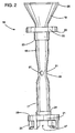
- the conduit 16 is formed from at least three sections.
- the first section A, of the three-section conduit component, as shown in Fig. 3 includes the upstream portion 17 of the conduit, the pressure reduction section 51 and the downstream portion 18 (with the exclusion of the horn section 19).
- the second section B may be termed a conduit bottom end cap and includes a first u-shaped channel 21 and the support legs 26 including the flow passages 27 through which fluid filtered only by the full flow filter 8 passes.
- the bottom end cap of the conduit can take the form of a circular-shaped lower section 80.
- the circular lower section includes inner flow passages 82 transiting through its walls, through which fluid is filtered by full flow filter 8 flows into the conduit 16.
- the circular-shaped lower section 80 also includes a lower u-shaped channel 84, which acts similar to the first u-shaped channel in the principle embodiment of the conduit 16.
- the horn section 19 and the second u-shaped channel 22 are preferably formed as a third section C, which may be termed a conduit top end cap, and which can be sealingly engaged with the first section A.
- a sealant such as Plastisol is applied to the three sections, at points where they engage each other.
- the conduit 16 can take any suitable form.
- a venturi is incorporated into the conduit 16
- the venturi is of a form that causes the fluid flow through the pressure reduction section 51 to be substantially linear fluid flow.
- One preferable form of venturi is one similar to the type of venturi used in venturi gauges that are known in the art. Filters incorporating such conduits demonstrate better flow qualities through the conduit as flow is directed in a linear fashion rather than in multiple directions. Thus, the ability of the filter apparatus to filter more fluid rapidly, and to cause a greater amount of fluid to be drawn through the bypass filter, is increased.
- the conduit of the present invention further comprises sealing members which may be attached to or molded in a unitary construction with the conduit 16.
- An example of such an embodiment of the present invention is shown in Fig. 3 wherein a sealing member 24 is positioned in an annular relationship around the upstream end 18 of the conduit.
- the sealing member 24 has an exterior which engages the first u-shaped channel 21 of the conduit and the upper end of the bypass support tube 52.
- a second sealing member 24, which may be similarly attached or molded is positioned at the downstream end 17 of the conduit and engages the second u-shaped channel 22, and has an exterior that can engage the upper end of a bypass support tube 52.
- the first u-shaped channel 21 is formed between the sealing member 24 and a first u-shaped channel outer retainer 28, which comprises a lip protruding towards the interior of the filter, and is used to sealingly engage the bypass filter 15 as described herein.
- the second u-shaped channel 22, is similarly formed between the sealing member 23 and a retainer 29 and also sealingly engages the bypass filter.
- bypass support tube 52 encircling the conduit 16 is a bypass support tube 52, comprising a tube perforated along its length to allow fluid to readily flow through it.
- the bypass support tube 52 can be formed of any material suitable for maintaining a spaced relationship between the conduit 16 and the bypass filter 15.
- the bypass support tube 52 is composed of steel, such as stainless steel.
- the bypass filter 15 may be formed from any suitable bypass media including such media as cellulose, synthetic fiber or micro-glass.
- the bypass filter 15 comprises a cellulose media.
- the bypass filter 15 is of a higher density than the full flow filter 8 and naturally resists passage of fluid when the fluid is offered the alternative of an open passage way, such as through the support legs 26.
- the bypass support tube 52 supports the bypass filter 15 and prevents pressure differential from collapsing the filter.
- bypass support tube 52 sets in the first u-shaped channel 21 and the bypass filter 15 is sealingly engaged in the first u-shaped channel 21 between the outer retainer of the u-shaped channel 28 and the bottom end of the bypass support tube 52.
- the upper end of the bypass support tube 52 rests in the second u-shaped channel 22 and the bypass filter 15 is sealingly engaged in the second u-shaped channel 22 between the outer retainer 29 of the second u-shaped channel and the top end of the bypass support tube 52.
- the bypass filter 15 is secured in this position within the first 21 and second 22 u-shaped channels by applying a sealant such as glue, or a curable compound sealant such as Plastisol, to create a seal between the bypass filter and u-shaped channels.
- the first section A is seated in the second section B in a sealing relationship.
- the bottom ends of the bypass support tube 52 and the bypass filter 15 are then seated in the first u-shaped channel 21.
- the second sealing member 24 sealingly engages a bottom end cap sealing member 25, which is attached to or integrally formed with, and protrudes into the interior of the filter from, the first u-shaped channel 21.
- the third conduit section C is then sealingly engaged to the first conduit section A, preferably by the sealing member 23 engaging a top end cap sealing member 36, which is attached or formed with the second u-shaped channel 22, while at the same time engaging the upper ends of the bypass support tube 52 and the bypass filter 15.
- the components in this type of embodiment i.e., sections A, B and C
- the full flow annulus 14 Surrounding the bypass filter is the full flow annulus 14.
- the full flow annulus 14 is formed by the spaced relationship between a full flow support tube 13 and the bypass filter 15.
- the full flow support tube 13 comprises a perforated tube that completely encircles the bypass filter 15.
- the full flow support tube 13 can be composed of any suitable rigid material.
- the full flow support tube 13 is composed of steel. More preferably, the full flow support tube 13 is composed of steel with a tin coating.
- the full flow filter 8 is composed of a material and designed so as to permit filtering of the entirety of the fluid entering the filter of the invention by the full flow filter.
- the full flow filter 8 may be formed from any suitable filter media for this purpose. Examples of suitable filter media for the full flow filter 8 include cellulose, synthetic fiber, or micro-glass Preferably, the full flow filter 8 is formed from micro-glass, synthetic fiber or other synthetic media. Similar to the bypass filter 15, the full flow filter 8 is preferably of a tubular shape to permit the encompassing of the bypass filter 15 and conduit 16 by the full flow filter 8.
- the full flow support tube 13 supports the full flow filter 8 and prevents pressure differential from collapsing the filter.
- the bottom end of the full flow filter 12 is sealingly engaged in a u-shaped channel formed within the interior end of the bottom end plate 5.
- the bottom end plate 5 is in the form of a u-shaped cap into which the bottom ends of the full flow support tube 13 and the full flow filter 8 fit, and are thus maintained in a spaced concentric relationship within the housing 1.
- the bottom end plate 5 preferably includes a depression 4 on the exterior of the cap into which the end of a coiled spring 2 is seated.
- this depression 4 which forms a raised area protruding into the interior of the closed end of the housing 1, the conduit support legs 26 are engaged and maintained in a fixed spaced relationship, thereby forming the flow passages 27 into the conduit 16.
- the u-shaped channel of the interior of the bottom end plate is formed between the protruding interior of the depression 4 and an outer retainer 6 of the bottom end plate which is connected at a right angle to the depression 4, and comprises a lip encircling the perimeter of the bottom end plate and protruding into the interior of the filter apparatus.
- the full flow filter 8 While no seal is required between the support legs 26 and the bottom end plate 5, because of the flow passages 27, the full flow filter 8 must sealingly engage the bottom end plate 5 to prohibit fluid from bypassing the full flow filter.
- the sealing is preferably accomplished by a curable compound such as Plastisol, which creates a seal between the bottom end of the full flow filter 8 and the bottom end plate 5.
- top end plate 30 Positioned at the open end of the housing 1 is a top end plate 30.
- the top end plate 30 is in the form of a circular plate encircling an open space through which fluid exiting the conduit flows.
- the top end plate 30 is formed from a single piece of material or is molded as a single integral component.
- the top end plate 30 can be formed of any material of suitable strength. Examples of such suitable materials include steel, aluminum or plastic.
- the top end plate 30 includes the end plate 31 (or body section), an outer retainer 32 connected and protruding towards the interior of the filter at a right angle to the outer perimeter edge of end plate 31, and an inner retainer 33 connected and protruding towards the interior of the filter at a right angle to the inner edge of the end plate 31.
- the inner retainer 33 is seated within the interior of the top end of the horn section 19 of the conduit, thereby forming a u-shaped channel on the interior end of the top end plate 30, between the exterior of the short straight section 20 of the conduit and the interior of the outer retainer 32 of the top end plate.
- the top end 11 of the full flow filter is engaged in this channel.
- the top end of the full flow filter 11 is secured within this u-shaped channel by the application of a Plastisol sealant applied to the top end of the full flow filter 11, the horn section 19 and the top end plate 30.
- the full flow support tube 13 may extend from the top end plate 30 to the bottom end plate 5 or the full flow filter may be any workable length less than the distance between the top end 30 and the bottom end plate 5 so long as adequate support is provided for the full flow filter.
- the housing 1 can comprise any shape suitable to filter fluids in the context of the present invention. As described elsewhere herein, the housing 1 is preferably formed from a cylinder having an open end and a closed end. An inlet annulus 3 is created between the housing 1 and the exterior of the full flow filter 8.
- the housing 1 can be made of any suitable material depending on the intended use of the apparatus. Examples of suitable materials include steel, aluminum, or plastic. Preferably the housing is made of steel.
- the various components are assembled in an orientation opposite to that seen in Fig. 1.
- the apparatus is assembled, as described above, using the top end cap 30 as base.
- a spring such as a coil spring 2
- the spring 2 is preferably formed from steel and has a spring force of about 240 kPa to about 345 kPa. The spring 2 is compressed between the interior of the closed end of the housing 1 and the depression 4 on the exterior of the bottom end plate 5.
- the filter of the present invention is completed using a first circular seal 70, a base plate 35, a seaming lid 60 and a second circular seal 65.
- the base plate 35 is used in conjunction with the first circular seal 70, which is placed between the top end plate 30 and the base plate 35.
- the first circular seal 70 is preferably formed from nitrile or another suitable rubber compound.
- the first circular seal 70 includes an upper lip 73, a body portion 75 and a lower lip 77.
- the lower lip 77 engages the post from the apparatus through which the filter of the present invention is attached to the apparatus such as an engine.
- the post of the apparatus extends down and through the center of the lower lip 77 in sealing engagement when the filter is attached thereto.
- the upper lip 73 and body portion 75 engage the base plate 35.
- the base plate 35 includes a conventional threaded passage 38 which engages the threads on the apparatus post (not shown).
- the base plate 35 also comprises a slanting first wall segment 40 which includes inlet ports 39, through which the fluid to be filtered passes, and an upturned internally threaded segment 38 which is suitable for engaging an oil inlet post (not shown).
- the inlet ports 39 are arranged angularly in a circular array around the perimeter of the threaded passage 38 and are located within the slanted first wall segment 40 of the base plate.
- the base plate 35 also includes a transition section 41 that extends outward from the slanted first wall segment 40 above the inlet ports 39 at a smaller incline than the first slanted wall segment.
- the base plate 35 further comprises an upturned outer lip 37, which is attached to the outermost portion of the transition section 41 and is positioned adjacent the outer open end of the housing 1.
- a seaming lid 60 is then attached to the base plate 35 and to the open end of the housing 1, as seen in Fig. 1 and Fig. 6.
- the seaming lid 60 preferably comprises a circular ring having an interior circular groove 61 that consists of a u-shaped channel with its open end facing towards the open end of the housing 1, and a downward turn outer rim 62 that surrounds the exterior of the seaming lid and protrudes beyond the periphery of both the base plate 35 and the housing 1.
- the seaming lid 60 is applied by placing the bottom side of the portion of the seaming lid that forms the circular groove 61 within the outer lip 37 of the base plate, and welding the bottom side of the seaming lid at the circular groove 61 to the transition section 41 of the base plate as seen in Fig. 6.
- this welding of the base plate 35 and seaming lid 60 occurs before sealing the filter.
- a second circular seal 65 is placed within the circular groove 61.
- the second circular seal 65 engages the apparatus, such as an engine, to effect a seal to prevent leakage of the outlet fluid passing from the apparatus to the filter.
- the second circular seal 65 may take the form of any of such well-known seals (e.g., a gasket) and preferably is smooth on the exterior surface.
- the second circular seal 65 is in the form of a flat seal that includes an undercut portion that fits within the circular groove 61 which assists in holding the second circular seal 65 in place.
- the seaming lid 60 preferably welded to the base plate 35 as described above, is applied to the filter of the present invention, compressing the spring 2.
- the outer rim 62 of the seaming lid 60 which is elevated above the circular groove 61, and which extends beyond the periphery of the base plate 35 and the housing 1, forms a channel into which the periphery of the open end of the housing 1 can fit.
- the housing 1 further comprises a slightly overturned outer lip (not shown) that extends beyond the periphery of the housing 1.
- the filter of the present invention includes the conduit, bypass and full flow filters and lower end cap 5 - in the manner described above.
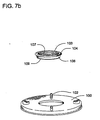
- the revision is seen in the top end plate 100, the base plate 110, and the seals for sealing the end plate, base plate, and housing 1.
- top end plate 100 is similar to that of the prior embodiment except that four leg extensions 102 extend in stepped configuration from the top surface of the top end plate 100.
- the top end plate 100 is molded from a plastic material such as nylon although other suitable materials may be used such as steel.
- a grommet type seal 103 Fitting into the circular inner opening of the top end plate 100 is a grommet type seal 103 that includes an upper lip 104, a body portion 106 and an inner seal ring 107.
- the inner seal ring 107 engages the post from the apparatus through which the filter of the present invention is attached to the apparatus such as an engine.
- the post extends down and through the center of the inner seal ring 107 in sealing engagement when the filter is attached to an appropriate apparatus such as an engine.
- the terminal end of the inner seal ring 107 includes a small outward facing lip 109 which engages the underside of the top end plate 100 to assist in holding the inner seal ring in place during assembly and use.
- the base plate 110 Resting on the four leg extensions 102 is the base plate 110.
- the base plate of the first alternative embodiment does not include inlet ports and, instead, is of solid construction without any such fluid passageways other than the threaded center passageway:
- the space between the base plate 110 and the top end plate created by the resting of the base plate 110 on the four leg extensions 102 permits the inlet fluid to pass from the apparatus and into the annulus between the housing and the full flow filter 8 between the base plate 110 and the top end plate 100.
- the base plate 110 includes a conventional threaded passage (not shown) which engages the threads on the apparatus post (not shown) to frictionally engage the filter of the invention.
- the base plate 110 also includes an outer lip 141 which is positioned adjacent the outer open end of the housing 1 and which is crimped in placed during sealing of the completed filter canister of the present invention. In this alternative embodiment, no seaming lid is necessary. Rather, the components are inserted into the housing 1, the spring 2 compressed, and the terminal end of the open end of the housing 1 is turned over and crimped in sealing over the upper lip of the base plate 110.
- a circular seal 150 is then used to engage the sealed end of the filter and, when in place, to engage the apparatus, such as an engine to effect a seal to prevent leakage of the outlet fluid passing from the apparatus to the filter.
- the circular seal 150 may take the form of any of such well-known seals and is smooth on the exterior surface.
- the circular seal 150 preferably includes a lower lip 152 and a body portion 154 connecting the lower lip 152 to an upper lip portion 156 which includes an upper sealing surface 158 and a lower sealing surface 160.
- the lower lip 152 engages the housing 1 just under the lip created by the folded over and crimped end of the housing.
- the lower sealing surface 160 likewise engages and seals against the overturned portion of the open end of the housing 1 while the upper sealing surface engages the apparatus, such as an engine.
- the upper sealing surface 160 may be smooth or include ribs to improve sealing.
- the filter of the present invention is constructed in a similar manner to that described in relation to the first alternative embodiment in relation to Fig. 7a and 7b, except for a variation to the top end plate 200 and the sealing mechanism 250.
- the sealing mechanism 250 is divided into two separate components, a circular seal 270 and a circular seal clip 280 as seen in, for example, Fig. 8c.
- the circular seal 270 can be any suitable type of circular seal.
- the circular seal includes at least one raised lip as shown in Fig. 8c.
- the circular seal is a d-ring shaped seal, which are well-known in the art.
- the d-ring shaped seal includes at least one flange, such as a top flange 290, attached to the d-shaped section of the seal which fits within a pocket 292 formed by the seal clip and/or sealing member as seen in, for example, Fig. 8b.
- the d-ring shaped seal includes two flanges, e.g., top flange 290 and bottom flange 294, oppositely positioned on both the lower and upper sides of the d-shaped section of the seal for assisting in retaining the seal, as seen in Fig. 8d.
- the top end plate preferably includes an inner rim 210 extending from the inner edge of the bottom of the inner passageway which supports, or acts as, a sealing member 220.
- the sealing member 220 can consist of a horizontal member (as shown in Figs. 8a, 8b and 8c), for example when the inner rim 210 itself acts as the sealing member 220, or, more preferably, the sealing member 220 is an upturned channel-forming d-ring sealing member (as shown in Fig. 13 and Fig. 15) positioned at the interior of the top end cap, which surrounds the outlet transiting through the top end cap.
- the sealing member 220 forms a seat on which the circular seal 270 rests.
- the circular seal 270 is further held in position by the seal clip 280, which is attached to the top end of the top end plate and extends below the horizontal level of the top end plate and engages the top end of the circular seal 270 as shown in Figures 8a, 8b, 13 and 15.
- the seal clip 280 can be composed of any suitable material for binding the circular seal 270.
- the seal clip 280 is composed of nylon.
- the connection between the seal clip 280 and the top end plate 200 can be accomplished by any suitable bond that retains the seal clip 280 in position and allows the seal clip 280, in conjunction with the d-ring sealing member 220, to engage the circular seal 270.
- the underside of the seal clip 280 is ultrasonically bonded to the top end cap 200.
- the circular seal 270 preferably includes an inner sealing surface 272, a lower sealing surface 273, and an upper rim 275.
- the circular seal rests on or is bonded to the top end plate inner rim 210 and/or sealing member 220 as described herein.
- the inner sealing surface 272 engages the post from the apparatus through which the filter of the present invention is attached to the apparatus such as an engine.
- the post extends down and through the center of the inner sealing surface 272 in sealing engagement when the filter is attached to an appropriate apparatus such as an engine.
- the circular seal is placed on the sealing member 220.
- a d-ring circular seal is placed between the sealing member 220 and a d-ring seal clip 280, whereby the sealing member and d-ring seal clip engage the d-ring seal.
- the seal clip 280 preferably includes upper surface 282 and a lower sealing surfaces 284.
- the seal clip preferably also includes an inner lip 286 and an outer lip 288.
- the lower sealing surface 284 of the seal clip engages the top surface of the top end plate and the inner lip 286 overlaps and engages the upper rim 275 of the circular seal 270.
- the upper surface 282 of the seal clip engages the base plate which, preferably, is identical to that of the first alternative embodiment.
- a d-ring type seal incorporating a d-ring type seal.
- the arrangement between a d-ring seal clip and a d-ring sealing member, if incorporated, can be any suitable arrangement for maintaining the d-ring in position.
- a d-ring clip 240 is positioned to engage the d-ring seal.
- the top end plate 230 in such an embodiment, preferably includes an r-shaped d-ring sealing member 232, attached to, or integrally formed with, the top end plate 230, which is positioned at the interior, rim of the top end plate, which surrounds the outlet (not shown) transiting through the top end plate.
- the r-shaped d-ring sealing member comprises an overturned top end 234 and a body section 236.
- the top end 234 of the r-shaped d-ring sealing member forms an overturned pocket 292 suitable for retaining the top flange 290 of a d-ring seal having two opposite flanged sides as shown in, for example, Fig. 8d.
- the body section 236 forms a straight section protruding into the interior of the filter apparatus, at the interior rim of the top end plate 230, transiting inward perpendicular (or about perpendicular) to the body.of the top end plate 230.
- the d-ring clip 240 includes a short horizontal top section 241 that is connected to a vertical body section 242, which is oriented perpendicular (or about perpendicular) to the top section and extends the length of the body section 236 of the d-ring sealing member.
- the body section 242 is connected to a horizontal bottom section 243, which is further connected to an upturned inner section 244.
- the bottom end of the body section 236 of the d-ring sealing member is seated on, and preferably attached to, the top end of the bottom section 243 of the d-ring clip.
- the top section 241 engages, and preferably is attached to, the bottom end of the top end plate 230, and fits within the corner formed at the juncture of the interior side of the body of the top end plate and the interior side of the body section 236 of the d-ring sealing member.
- the upturned inner section 244 and bottom section 243 in concert with the interior side of the bottom end of the body section 236 of the d-ring sealing member forms a pocket 296 capable of retaining the bottom flange 294 of the two-side flanged d-ring seal.
- the d-ring clip 240 is attached to the d-ring sealing member and/or top end plate by any suitable attachment capable of maintaining a form for retaining a d-ring seal.
- the d-ring clip 240 is sealed by ultrasonic bonding. More preferably, the d-ring clip 240 is sealed to the top end plate 230 and integrally formed d-ring sealing member by ultrasonic bonds between the top section of the d-ring clip 241 and the interior side of the top end plate 230 and by a second ultrasonic bond between the bottom portion of the d-ring clip 243 and the bottom of the body section 236 of the d-ring sealing member.
- a third alternate embodiment of the present invention incorporates such an alternate transition in the context of a filter apparatus having a housing 300, which comprises a separated inlet 335 and outlet 330 therein. Due to the separated inlet 335 and outlet 330, this third alternate embodiment does not incorporate a base plate, and may or may not utilize a seaming lid. Filters incorporating housings with similar separated inlet and outlet components are known in the art, such as those described in U.S. Patents 5,342,511 and 5,078,877.
- the filter of the third alternate embodiment of the invention shown in Fig. 9 includes among the replaceable components of the apparatus, full flow and bypass filters (as described herein) and a venturi conduit, concentrically arranged around each other within housing 300.
- the conduit of the third alternate embodiment comprises a pressure reduction section, comprising a section of reduced diameter located near the center of the conduit. Located near the pressure reduction section is one or more bypass conduits, preferably two simple orifices as described elsewhere herein.
- a horn-shaped transition section 311 Attached to, or integrally formed as a component of, the downstream end of the conduit of the third alternate embodiment is a horn-shaped transition section 311.
- the horn-shaped transition section 311 has a diameter greater than the downstream end of the conduit of the third alternate embodiment, and which gradually increases in diameter towards its downstream end.
- the exterior of the horn-shaped transition section 311 is surrounded by a top end cap sealing member 309, which encircles the outside of the horn-shaped transition section 311, near the downstream end of the horn-shaped transition section.
- the top end cap sealing member 309 sealingly engages an O-ring 305, preferably by an O-ring groove in the top end cap sealing member (not shown).
- the O-ring 305 is attached to the interior of the housing 300 of the third alternate embodiment, preferably attached to a conduit support 301, which comprises a structure, preferably circular in shape, that protrudes into the interior of the housing 300 of the third alternate embodiment, and which preferably encircles the outlet 330 of the filter apparatus.
- the connection between the top end cap sealing member 309 and O-ring 305 secures the horn-shaped transition section 311 in position such that the downstream end of the horn-shaped transition section 311 communicates with the outlet 330.
- a base plate transition and a horn section (or horn-shaped transition section) between the conduit and the outlet of the filter apparatus.
- a top end cap design that excludes a horn section is shown in Fig. 10.
- a top end cap 400 comprising a circular end cap encircling an outlet 410 is incorporated.
- the top end cap 400 has a relatively uniform diameter (i.e., versus a horn section or horn-shaped transition section described elsewhere herein), and is attached to a top end cap sealing member 420, preferably by welding the top end cap sealing member within the upper rim 415 of the top end cap outlet to the lower portion 450 of the top end cap sealing member.
- the top end cap sealing member 420 has an O-ring groove 430 which engages an O-ring 440.
- the O-ring 440 can be attached to any suitable structure within the filter apparatus, such as attachment to conduit supports protruding into the interior of the housing (not shown).
- FIG. 11 Another example of an embodiment of the present invention that does not incorporate a base plate or horn section in the transition from the downstream end of the conduit to the outlet, is shown in Fig. 11.
- a filtering apparatus incorporating a venturi conduit 16 comprising a pressure reduction section 51 and bypass port 57, is concentrically surrounded by bypass and full flow filters, and a housing, as described elsewhere herein.
- the top end cap 500 comprises a conduit sealing member 501, consisting of a hollow tubular section extending above and below a solid top bypass filter support.
- the conduit sealing member 501 sealingly engages the interior of the downstream end of the conduit (fitting therein) and thereby communicating therewith to allow fluid exiting the conduit to pass through to the outlet 550 and into a connected apparatus, such as an attached engine base.
- the top end cap 500 of this embodiment further comprises a top bypass filter support 502 and a t-shaped side bypass filter support 503.
- the interior end of the t-shaped side bypass filter support 503 and the top bypass filter support 502 in combination with the exterior of the downstream end of the conduit 16 form a u-shaped channel wherein the top end of the bypass filter 15, is sealingly engaged, as described with reference to other embodiments herein.
- the exterior end of the t-shaped side bypass filter support 503 engages an end cap seal 570 and/or a full flow top end cap 590, and sandwiches the end cap seal 570 between the t-shaped side bypass filter support 503 and a circular base plate 560 or the full flow top end cap 590, which in turn engages the circular base plate 560.
- the full flow top end cap 590 thus engages the top end cap, and maintains the top end of the full flow filter 8 and the top end of the full flow filter support tube 13 in position, as described with regards to other embodiments herein.
- the end cap seal 570 ensures that fluid mixed with impurities entering the filtering apparatus through an inlet 575 does not mix with filtered fluid exiting the outlet 550.
- the base plate 560 engages a circular apparatus seal 580, sandwiching the circular apparatus seal between the attached apparatus (e.g., an engine as shown) and the filtering apparatus of the present invention, securing the filtering apparatus in relation to an attached apparatus.
- the downstream end of the conduit can communicate with the outlet 550 and directly into an attached apparatus, such as the base of an engine as shown.
- An embodiment of the invention as shown in Fig. 11, that incorporates such a direct transition without a horn section can provide better direction of flow of fluid from the conduit of the filtering device of the present invention.
- the present invention alternatively provides a filtering apparatus incorporating alternate base plates, wherein the base plate rests directly upon and/or is sealingly engaged to the top end cap.
- the inlet ports are positioned within the threaded passage of the base plate, versus being arranged in an array around the uppermost portion (i.e., the base plate lip) as described elsewhere herein.
- no support legs or other spacing arrangement between the top end cap and base plate or end plate is required to permit flow into the filter. Consequently, the full flow and/or bypass filters in such embodiments may have increased length, thereby increasing the overall performance of the filter apparatus.
- the need for seals between the base plate and the top end cap can be reduced or eliminated.
- the invention provides a base plate 600 that comprises a circular threaded passage 610 through which inlet ports 620 are positioned.
- the base plate comprises a transition portion 640, an outer lip 630, and a threaded portion 610 through which the inlet ports 620 pass.
- the inlet port 620 can comprise any suitable orifice transiting through the threaded portion 610.
- the inlet port 620 comprises a slotted hole having a chamfer (or being chamfered) around the slotted hole.
- the terminal end 635 of the base plate 600 abuts the top of the top end cap 30.
- Inlet fluid passes through the inlet ports 620 and into the inlet annulus between the housing and the full flow filter.
- FIG. 14a, 14b and 15 A second alternate base plate embodiment of such an apparatus is shown in Fig. 14a, 14b and 15. This embodiment is similar to that of Fig. 12a, 12b and 13.
- a base plate 700 having a circular threaded passage 710, an outer lip 750, a transition portion 740, and four stepped areas 730 is incorporated into the apparatus of the interior present invention.
- the stepped areas 730 are positioned at about equal distance from each other around the center of the threaded passage (i.e., the outlet in such an embodiment), and are formed by removing a portion of the wall thickness of the threaded passage 710.
- the stepped areas 730 can be integrally formed with or created by removing material after initial formation of the threaded passage portion 710 of the base plate.
- the stepped areas form inlet chambers 760, comprising the space between the stepped area 730 and the threaded passage 710.
- An inlet port 720 is placed within each stepped area 730.
- the inlet port 720 can comprise any suitable orifice, preferably comprising a slotted hole having a chamfer (or being chamfered) around the slotted hole.
- inlet fluids may pass around the terminal end of the post and either through the inlet port directly or pass through the space between the stepped area and the post and then into and through the inlet port. The inlet fluid then passes to the annulus between the housing and the full flow filter.
- the top end plate 800 includes inner positioning tabs 810 and outer positioning tabs 820 that consist of sections on the exterior of the top end plate 800 that are raised to suitable level to assist in the positioning of the base plate during the assembly of the filter apparatus.
- the bottom of the base plate fits within the space between inner positioning tabs 810 and outer positioning tabs 820, and the inner positioning tabs 810 and outer positioning tabs 820 engage the inner and outer peripheries of the base plate such that the assembled filter components of the filtering apparatus are maintained in a stable position on the base plate while the spring is applied and filter apparatus sealed, as described elsewhere herein.
- the inner positioning tabs and outer positioning tabs can be in any arrangement suitable for maintaining the base plate in position during assembly.
- the positioning tabs are arranged in separated areas as shown in Fig. 16.
- the positioning tabs form continuous rings on the top surface of the top end cap, as shown in Fig. 16a.
- fluid flows into the filter after passing from the apparatus outlet and through either the base plate passages (which can be positioned either within the threaded passage of the base plate or elsewhere therein), between the base plate and top end plate, or directly into a separated inlet and through an inner inlet.
- the fluid then passes into the inlet annulus 3, where it is contained by the walls of the housing 1, the bottom end plate 5, and the upstream side 9 of the full flow filter.
- the inlet fluid then flows through the full flow filter 8, exiting through the full flow filter's downstream side 10 and the full flow support tube.
- the fluid After passing through the full flow filter 8 and support tube, the fluid is in the full flow annulus 14. Fluid within the full flow annulus 14 may then pass through the bypass filter 15, into the bypass annulus 53 and then through the venturi bypass port 57 and into the conduit 16, or the fluid may pass from the full flow annulus through the flow passages 27 and into the conduit 16. Thus, the full flow filtered fluid will either pass directly through the conduit and out of the filter or will be further filtered by the bypass filter 15 and then flow out of the filter. Given the relative sizes of the flow passages 27 as compared to the bypass port 57, the path of least resistance for the fluid generally will be through the flow passages 27, and a majority of the fluid usually will flow through the flow passages.
- the conduit 16 in the present embodiment of the invention accomplishes this in part by taking the form (at least in part) a venturi or other suitable pressure reduction configuration.
- the conduit 16 has a pressure reduction section 51 (preferably comprising a venturi throat 55) whereby flow speed of the fluid through the conduit 16 is increased, and thus pressure is lowered within the conduit 16.
- This lower pressure results in a pressure differential across the bypass filter 15 communicated via the bypass port 57 which is positioned in the pressure reduction section 51, preferably at the throat 55, the narrowest portion of the conduit 16.
- the present invention provides apparatuses and methods wherein the amount of fluid that is to be drawn across the bypass filter 15 can be pre-determined, in an at least significant part, by varying the size of the bypass port 57 and/or by increasing the number of bypass ports. Because flow rate is proportional to the cross-sectional area of any orifice, by changing the cross-sectional area of the bypass port 57 the velocity of fluid entering the conduit 16, and thus the resulting pressure change from the bypass annulus 53 to within the conduit 16, can be pre-determined.
- the amount of narrowing of the diameter of the pressure reduction section 51 and/or the diameter of the upstream 17 and downstream 18 ends of the conduit can also be varied to increase or decrease the draw of fluid across the bypass filter 15.
- the present invention provides methods and apparatuses whereby a pre-determined amount of fluid can be filtered through both the full flow 8 and the bypass 15 filters.
- the bypass filter 15 effectively removes the impurities of small size from a pre-determined amount of fluid, while the impurities of large size are captured by the full flow filter 8.
- the present invention is not limited to the features explained above; rather, many modifications and alternations can be conceived by those skilled in the art within the scope of the invention.
- the full flow and bypass filters may be formed in various manners and of various materials as mentioned above.
- This example demonstrates the effectiveness of the apparatus and method of the claimed invention to filter a pre-determined amount of fluid by both full flow and bypass filtration.
- Filter apparatuses incorporating the features of the first embodiment of the present invention, as described herein, were selected having either (1) only a full flow filter, or (2) a full flow filter, bypass filter, and conduits having two opposite positioned bypass ports with about 4,5 mm diameters, various internal diameters in the pressure reduction section, and various internal diameters in the upstream and downstream ends of the conduit (as measured at about the middle of either the upstream or downstream end).
- results of these experiments indicate that the combination of a full flow filter and bypass filter with a conduit having a pressure reduction section improved filtration over systems that relied on full flow filtration only. Moreover, the results of these experiments demonstrate that by varying the internal diameter of the conduit (e.g., at the upstream and downstream ends) and the pressure reduction section of the conduit, improved contaminant removal efficiency by the combination of the full flow and bypass filters is achieved. Furthermore, the results of the experiments demonstrate that by varying the diameter of the upstream and downstream ends and the pressure reduction section of the conduit of the present invention relatively, a pre-determined amount of fluid can be filtered by both full flow and bypass filtration and a predetermined filtration efficiency may be arrived at.
- the predetermined percentage of flow through the bypass filter may be calculated using the measured reduction in particulates in conjunction with the stated efficiency of the bypass filter as compared to the filtration achieved by the full flow filter alone.
- the reduction of impurities attributable solely to filtration by the bypass filter coupled with that filter's efficiency permits the calculation of the percentage of total flow passing through the bypass filter.
Landscapes
- Chemical & Material Sciences (AREA)
- Chemical Kinetics & Catalysis (AREA)
- Lubrication Details And Ventilation Of Internal Combustion Engines (AREA)
- Filtration Of Liquid (AREA)
- Water Treatment By Sorption (AREA)
Claims (23)
- Un appareil à filtres utilisé pour éliminer les impuretés, composé de :un boîtier (1)un filtre à huile en circuit principal(8), qui est inclus dans ledit boîtier(1), ledit boîtier (1) et ledit filtre à huile en circuit principal (8)étant disposés de telle manière que l'ensemble du fluide à filtrer par ledit appareil passe à travers ledit filtre à huile en circuit principal (8) caractérisé en ce que :un filtre à huile en dérivation (15) est placé de manière concentrique à l'intérieur dudit filtre à huile en circuit principal (8), etune conduite (16) est placée en partie de manière concentrique à l'intérieur dudit filtre à huile en dérivation (15), ladite conduite (16) étant constituée d'une fin supérieure (17) et d'une fin inférieure (18), d'un réducteur de pression (51) se trouvant à l'intérieur dudit filtre à huile en dérivation (15), et d'au moins une ouverture,(57) allant d'une zone de basse pression située dans ledit réducteur de pression (51) jusqu'à une position proche du côté inférieur dudit filtre à huile en dérivation (15),ledit filtre à huile en dérivation (15) se trouvant au-dessous dudit filtre à huile en circuit principal (8) et ledit réducteur de pression (51) est installé à l'intérieur dudit appareil à filtre de sorte qu'un différence de pression se crée à travers ledit filtre à huile en dérivation (15) lorsqu'un fluide traverse ledit appareil à filtres, de sorte qu'une quantité dudit fluide à filtres par ledit appareil à filtrer para l'appareil à filtres traverse ledit filtre à huile en dérivation (15).
- L'appareil à filtres de la revendication 1, caractérisé en ce que ledit réducteur de pression (51) comprend un disque, une tuyère de large diamètre, une tuyère Dall ou un venturi.
- L'appareil à filtres de la revendication 2, caractérisé en ce que le réducteur de pression (51) comprend un venturi.
- L'appareil à filtres de la revendication 3, caractérisé en ce que le venturi (51) comprend une gorge (55) d'un diamètre intérieur d'environ 24 mm.
- L'appareil à filtres de l'une des revendications 1 à 4, caractérisé en ce qu'il présente au moins une ouverture (57) qui se compose de deux ouvertures, chaque ouverture (57) ayant un diamètre de 4,3 mm à environ 4,6 mm.
- L'appareil à filtre de la revendication 5, caractérisé en ce que le diamètre intérieur de la fin supérieure (17) et de la fin inférieure (18) de ladite conduite (16) se situe entre environ 18 mm et 30,5 mm.
- L'appareil à filtres de la revendication 6, caractérisé en ce que le diamètre intérieur de ladite fin supérieure (17) et de ladite fin inférieure (18) de ladite conduite (16) est approximativement de 28,6 mm.
- l'appareil à filtres de l'une des revendications 1 à 7, caractérisé en ce que l'appareil à filtres comprend un capuchon au niveau de la fin supérieure (C), ledit capuchon de la fin supérieure (C)se trouvant sur la fin supérieure dudit filtre à huile en dérivation (15).
- L'appareil à filtres de la revendication 8, caractérisé en ce que ledit capuchon de la fin supérieure (311) comprend de plus un élément de verrouillage du capuchon (309)sur la fin supérieure, disposant d'un joint torique s'engrenant dans un joint torique d'étanchéité afin de verrouiller (305).
- L'appareil à filtres des revendications 8 ou 9, caractérisé en ce que ledit appareil comprend de plus une plaque sur la fin supérieure (30), ladite plaque de la fin supérieure (30) s'engrenant dans la fin supérieure (11) dudit filtre à huile en circuit principal(8).
- Selon la revendication 10, l'appareil est caractérisé en ce que ladite plaque de la fin supérieure (230) comprend un élément de verrouillage de l'anneau en D (232) capable de s'engrener dans un joint d'anneau en D afin de verrouiller (290).
- Selon la revendication 10, l'appareil à filtres est caractérisé en ce que ledit appareil à filtres comprend de plus un joint de guidage (103) et une plaque de base (110),
la plaque de fin supérieure incluant de plus un bord intérieur (33) s'engrenant également dans ledit joint de guidage (103) et dans les rallonges de pied (102), tandis que lesdites rallonges de pied (102) supportent ladite plaque de base (110) formant ainsi un passage (27) entre lesdites rallonges de pied (102) et ladite plaque de base (110). - Selon la revendication 11, l'appareil à filtres, l'appareil à filtres comprend de plus une pince d'étanchéité (280), la pince d'étanchéité (280) s'engrenant das ledit joint de guidage (103).
- L'appareil à filtres de la revendication 1, l'appareil à filtres comprend de plus une plaque de base (600), ladite plaque de base (600) incluant un passage fileté (610) et au moins un orifice d'alimentation (620), ledit orifice d'alimentation (620) traverse une cloison dudit passage fileté(610). Ladite plaque de base (600) est placée face au dit boîtier (1) et au dit filtre à huile en circuit principal (8) de sorte que ledit fluide entrant traverse ledit orifice d'alimentation (620) et passe ensuite par le filtre à huile en circuit principal (8).
- Dans l'appareil à filtres de la revendication 1, la conduite est constituée de :a. une première section de conduite supérieure (B) comprenant un capuchon sur la fin inférieure.b. une deuxième section de conduite (A) constituée dudit réducteur de pression (51) et d'au moins une ouverture (57) par la cloison dudit réducteur de pression (51), etc. une troisième section de conduite inférieure (C) comprenant un capuchon sur la fin supérieure, le capuchon de la fin supérieure incluant au moins un passage (27), ledit passage (27) étant transversal à la direction du fluide au travers de ladite conduite (16), ladite conduite étant imperméable au fluide excepté au travers dudit passage (27) et de ladite ouverture (57),la première section de conduite supérieure (B) est bloquée dans ladite deuxième section de conduite (A), et ladite deuxième section de conduite (A) est également bloquée dans ladite troisième section de conduite inférieure (C) de sorte que le fluide entrant ladite première section de conduite supérieure (B) traverse ladite deuxième section de conduite (A) et ladite troisième section de conduite inférieure (C).
- Selon la revendication 17, l'appareil à filtres, caractérisé en ce que ledit réducteur de pression (51) présente la forme d'un venturi.
- Selon la revendication 18, l'appareil à filtres, caractérisé en ce qu'au moins une ouverture (57) comprennent deux ouvertures, chacune desdites ouverture (57) possédant un diamètre compris entre 4,3mm et 4,6mm, ledit venturi (51) présentant une gorge constituée d'un diamètre intérieur d'environ 24mm et ladite première section de conduite (B) présentant un diamètre intérieur d'environ 28,6 mm.
- L'appareil à filtres selon l'une des revendications 15 à 17, caractérisé en ce que ladite conduite comprend de plus une section cornée (19), ladite section cornée (19) étant placée en bas de ladite troisième section de conduite inférieure (C).
- L'appareil à filtres selon l'une des revendications 15 à 18, ladite conduite (16) comprenant de plus au moins deux pieds de support (26) reliés à la fin supérieure de ladite première section de conduite supérieure (B), lesdits pieds de support (26) constituant un certain nombre de dits passages(27).
- L'appareil à filtres selon l'une des revendications 15 à 20, ledit capuchon d la fin inférieure (B) comprenant un premier canal en forme de U (21) et ledit capuchon de la fin supérieure (C) comprenant un deuxième canal en forme de U (22), un filtre à huile en dérivation (15) peut être engrené entre les deux canaux en forme de U (21,22).
- Un appareil à filtres constitué de la conduite de la revendication 21, caractérisé en ce que ledit appareil à filtres comprend de plus un filtre à huile en dérivation (15) bloqué entre les deux canaux en forme de U (21,22).
- Une méthode permettant d'éliminer par filtration les impuretés contenues dans un fluide, caractérisée par :(a) l'introduction d'un fluide dans un appareil de filtration comprenant un filtre à huile en circuit principal généralement cylindrique (8) et un filtre à huile en dérivation généralement cylindrique (15), le filtre à huile en dérivation (15) étant placé de manière concentrique par rapport au filtre à huile en circuit principal (18), avec un filtre (8,15) positionné au moins partiellement à l'intérieur de l'autre filtre (8,15) ;(b) la filtration de 100% dudit fluide à l'aide dudit filtre à huile en circuit principal (8) en faisant couler ledit fluide de manière radiale au travers du filtre à huile en circuit principal (8) et vers une chambre annulaire (14) également de manière radiale entre le filtre à huile en circuit principal (8) et le filtre à huile en dérivation (15) ;(c) la création d'une différence de pression à travers le filtre à huile en dérivation (15), tandis qu'une section prédéfinie dudit fluide filtré par le filtre à huile en circuit principal (8) est tiré à partir de la chambre annulaire (14) de manière radiale au travers dudit filtre à huile en dérivation (15), filtrant ainsi une nouvelle fois ladite section prédéfinie dudit fluide.
- La méthode de la revendication 22, caractérisée en ce que ladite différence de pression résultant du passage d'une section prédéfinie dudit fluide au travers dudit filtre à huile en circuit principal (8) passant ensuite autour d'une fin du filtre à huile en dérivation (15) et au travers d'une conduite (16) comprenant un réducteur de pression (51), ledit passage du fluide au travers dudit réducteur de pression (51) créant ainsi une différence de pression au travers dudit filtre à huile en dérivation (15).
Applications Claiming Priority (2)
| Application Number | Priority Date | Filing Date | Title |
|---|---|---|---|
| US09/487,126 US6478958B1 (en) | 2000-01-19 | 2000-01-19 | Apparatus for filtering impurities out of fluid |
| US487126 | 2000-01-19 |
Publications (3)
| Publication Number | Publication Date |
|---|---|
| EP1118368A2 EP1118368A2 (fr) | 2001-07-25 |
| EP1118368A3 EP1118368A3 (fr) | 2002-02-06 |
| EP1118368B1 true EP1118368B1 (fr) | 2006-03-08 |
Family
ID=23934517
Family Applications (1)
| Application Number | Title | Priority Date | Filing Date |
|---|---|---|---|
| EP00204283A Expired - Lifetime EP1118368B1 (fr) | 2000-01-19 | 2000-12-01 | Dispositif et procédé de filtration de fluides |
Country Status (9)
| Country | Link |
|---|---|
| US (2) | US6478958B1 (fr) |
| EP (1) | EP1118368B1 (fr) |
| JP (2) | JP5328066B2 (fr) |
| AT (1) | ATE319511T1 (fr) |
| AU (1) | AU1501201A (fr) |
| CA (1) | CA2316061A1 (fr) |
| DE (1) | DE60026447T2 (fr) |
| ES (1) | ES2259976T3 (fr) |
| MX (1) | MXPA01000377A (fr) |
Cited By (1)
| Publication number | Priority date | Publication date | Assignee | Title |
|---|---|---|---|---|
| US11590436B2 (en) | 2017-06-01 | 2023-02-28 | Winchester Global Pty Ltd | Bypass and full flow combination filter |
Families Citing this family (94)
| Publication number | Priority date | Publication date | Assignee | Title |
|---|---|---|---|---|
| US6969461B2 (en) | 2000-01-19 | 2005-11-29 | Baldwin Filters, Inc. | Combination particulate and acid-neutralizing filter |
| US6478958B1 (en) * | 2000-01-19 | 2002-11-12 | Baldwin Filters, Inc. | Apparatus for filtering impurities out of fluid |
| US6818125B2 (en) | 2000-04-24 | 2004-11-16 | Vortex International, Llc | Engine block with angled oil outlets |
| US6666968B2 (en) * | 2001-03-22 | 2003-12-23 | Vortex International, Llc | Fluid filtration apparatus |
| US6968710B1 (en) * | 2002-03-26 | 2005-11-29 | Kozinski Richard C | Refrigeration compressor capacity limiting device |
| US6919023B2 (en) * | 2002-06-07 | 2005-07-19 | Baldwin Filters, Inc. | Acid neutralizing filter canister |
| US7014761B2 (en) * | 2002-06-07 | 2006-03-21 | Baldwin Filters, Inc. | Environmentally friendly dual lube venturi filter cartridge |
| GB2389806B (en) * | 2002-06-07 | 2005-10-26 | Baldwin Filters Inc | Housing for environmentally friendly filter cartridge |
| US7232521B2 (en) * | 2002-06-07 | 2007-06-19 | Baldwin Filters, Inc. | Environmentally friendly acid neutralizing cartridge |
| US7168573B2 (en) * | 2002-06-07 | 2007-01-30 | Baldwin Filters, Inc. | Environmentally friendly filter cartridge |
| GB2414422B (en) * | 2002-06-07 | 2006-06-14 | Baldwin Filters Inc | Environmentally friendly acid neutralizing full flow cartridge |
| EP1437166A1 (fr) * | 2003-01-09 | 2004-07-14 | NTZ Nederland BV | Filtre de remplacement à flux principal et procédé associé |
| EP1440719A1 (fr) * | 2003-01-09 | 2004-07-28 | NTZ Nederland BV | Filtre de remplacement unidirectionnel et procédé associé |
| WO2004037379A2 (fr) * | 2003-02-11 | 2004-05-06 | Ntz Nederland Bv | Dispositif mecanique a filtre standard et microfiltre |
| EP1452216A1 (fr) * | 2003-02-11 | 2004-09-01 | NTZ Nederland BV | Appareil de filtrage |
| WO2004080568A1 (fr) * | 2003-03-10 | 2004-09-23 | Ntz International Holding Bv | Element de filtration |
| US7175761B2 (en) * | 2003-11-18 | 2007-02-13 | Champion Laboratories, Inc. | Fluid filter assembly |
| US7704396B2 (en) * | 2003-12-15 | 2010-04-27 | Filtran Llc | Coaxial full-flow and bypass oil filter with spring/gasket arrangement |
| US7090773B2 (en) * | 2003-12-15 | 2006-08-15 | Spx Corporation | Coaxial full-flow and bypass oil filter |
| US20060226065A1 (en) * | 2003-12-15 | 2006-10-12 | Meddock Leroy J | Coaxial full-flow and bypass oil filter apparatus and method |
| US7704397B2 (en) * | 2003-12-15 | 2010-04-27 | Filtran Llc | Coaxial full-flow and bypass oil filter having cap with blades |
| WO2005087344A2 (fr) * | 2004-03-05 | 2005-09-22 | Donaldson Company, Inc. | Ensemble de filtre de liquide destine a etre utilise avec un agent de traitement, et procedes |
| BRPI0508483A (pt) * | 2004-03-05 | 2007-07-31 | Donaldson Co Inc | conjunto de filtro de lìquido de carga superior para uso com agente de tratamento e métodos |
| MXPA06011808A (es) | 2004-04-13 | 2006-12-15 | Donaldson Co Inc | Cartucho de filtro para filtracion de liquidos. |
| US20050252838A1 (en) | 2004-05-13 | 2005-11-17 | Baldwin Filters, Inc. | Fluid filtration apparatus and method |
| WO2005123222A1 (fr) | 2004-06-14 | 2005-12-29 | Donaldson Company, Inc. | Dispositif, ensemble et procedes de filtrage de l'air |
| WO2006010983A1 (fr) * | 2004-07-09 | 2006-02-02 | Ntz International Holding | Filtre a noir de fumee, filtre, dispositif venturi et moteur diesel |
| BRPI0514104B8 (pt) | 2004-08-06 | 2016-10-11 | Donaldson Co Inc | arranjo de cartucho de filtro, limpador de ar e método para formar um arranjo de cartucho de filtro |
| US7250126B2 (en) * | 2004-08-11 | 2007-07-31 | Fleetguard, Inc. | Acid-neutralizing filter media |
| WO2006076479A1 (fr) | 2005-01-13 | 2006-07-20 | Donaldson Company, Inc. | Cartouche et assemblage de filtre a air |
| JP5053099B2 (ja) | 2005-01-13 | 2012-10-17 | ドナルドソン カンパニー,インコーポレイティド | エアフィルタ装置 |
| US20060191832A1 (en) * | 2005-02-14 | 2006-08-31 | Richie Bryant L | Dual media fuel filter and fuel/water separator cartridge filter system |
| US7597734B2 (en) * | 2005-04-05 | 2009-10-06 | Donaldson Company, Inc. | Multi-element filter arrangement and methods |
| US7524416B1 (en) * | 2005-08-25 | 2009-04-28 | Bergmen Engineering, Inc. | Spin-on oil filter adaptor for engines equipped with internal paper cartridge oil filters |
| BRPI0618614B1 (pt) * | 2005-11-15 | 2021-10-13 | Donaldson Company, Inc | Arranjo de filtro de líquido e elemento de filtro |
| US7372763B2 (en) * | 2005-12-28 | 2008-05-13 | Intel Corporation | Memory with spatially encoded data storage |
| US7625419B2 (en) | 2006-05-10 | 2009-12-01 | Donaldson Company, Inc. | Air filter arrangement; assembly; and, methods |
| WO2007149497A2 (fr) * | 2006-06-20 | 2007-12-27 | Cummins Filtration Inc. | Éléments de filtration remplaçables comprenant différentes substances de filtration et systèmes, techniques et méthodes de filtration associés |
| US20080060991A1 (en) * | 2006-09-11 | 2008-03-13 | Gaither John D | Combination valve including anti-drainback valve with slits |
| US8273143B2 (en) * | 2006-10-06 | 2012-09-25 | Donaldson Company, Inc. | Air cleaner, replaceable filter cartridges, and methods |
| WO2008112997A1 (fr) * | 2007-03-15 | 2008-09-18 | Honeywell International Inc. | Filtre de conditionnement d'huile lubrifiante contenant un conditionneur pastillé amélioré |
| EP2190554B1 (fr) | 2007-09-07 | 2013-01-09 | Donaldson Company, Inc. | Ensemble filtre à air |
| EP2197563A1 (fr) * | 2007-10-02 | 2010-06-23 | Donaldson Company, Inc. | Agencement de filtre à liquides, composants et procédés |
| US20090114580A1 (en) * | 2007-11-01 | 2009-05-07 | Zafar Hussain | One piece tapping plate for heavy duty filters |
| EP2247358A1 (fr) * | 2008-01-24 | 2010-11-10 | Donaldson Company, Inc. | Configuration de filtre en combinaison et procédé correspondant |
| KR100974720B1 (ko) * | 2008-05-23 | 2010-08-06 | 현대자동차주식회사 | 연료 필터 앗세이 |
| US8080159B2 (en) * | 2008-08-19 | 2011-12-20 | Cummins Filtration Ip, Inc. | Centertube for a combination full flow and bypass filter apparatus |
| EP2168469B1 (fr) * | 2008-09-25 | 2013-07-17 | Nestec S.A. | Cartouche de filtre pour machine à boissons et machine à boissons dotée d'une cartouche de filtre |
| CN102264451B (zh) * | 2008-10-10 | 2014-12-24 | 瑟吉奎斯特公司 | 多流过滤系统 |
| EP2379196B1 (fr) | 2008-12-18 | 2016-07-06 | FRAM Group IP LLC | Illet d'étanchéité pour filtres à fluide |
| US8061530B2 (en) | 2009-04-09 | 2011-11-22 | Cummins Filtration Ip, Inc. | Filtration sealing system |
| US8480885B2 (en) * | 2009-05-18 | 2013-07-09 | Purolator Filters Na Llc | Full flow liquid filter with integral bypass filtration |
| US8470175B2 (en) * | 2009-09-15 | 2013-06-25 | Purolator Filters Na Llc | Space reducing filter with supplemental fluid processing element |
| KR20120095868A (ko) | 2009-09-15 | 2012-08-29 | 푸로레이터 필터스 엔에이 엘엘씨 | 주 필터 요소 및 보조 필터 요소를 갖는 필터 및 선택적 기포 파괴기 |
| US8414766B2 (en) * | 2009-10-14 | 2013-04-09 | GM Global Technology Operations LLC | Serviceable oil filter device |
| DE102010044169A1 (de) | 2010-11-19 | 2012-05-24 | Mahle International Gmbh | Hydraulikfilter |
| JP5299418B2 (ja) * | 2010-12-23 | 2013-09-25 | 株式会社デンソー | 燃料フィルタ |
| DE102011013003C5 (de) * | 2011-03-04 | 2021-01-07 | Optek-Danulat Gmbh | Durchströmbare pH-Messzelle |
| US20120241366A1 (en) * | 2011-03-22 | 2012-09-27 | Clark Filter, Inc. | Particulate and Bypass Filter and Locomotive Oil Lube Filtration System |
| CN103687658B (zh) | 2011-06-30 | 2016-05-04 | 唐纳森公司 | 空气/油分离器组件、部件和方法 |
| US9358485B2 (en) | 2011-08-19 | 2016-06-07 | Baldwin Filters, Inc. | Hydraulic spin-on filter cartridge having base plate supporting radially directed seal |
| US20130133631A1 (en) * | 2011-11-30 | 2013-05-30 | Caterpillar Inc. | System to measure parameters of a particulate laden flow |
| KR101936742B1 (ko) * | 2012-12-04 | 2019-04-09 | 코웨이 주식회사 | 수처리장치 |
| CN114887415B (zh) | 2013-06-28 | 2024-03-26 | 唐纳森公司 | 用于空气滤清器组件的过滤器滤芯 |
| CN103349858B (zh) * | 2013-07-11 | 2015-12-23 | 蔡泽义 | 用于净水设备的过滤装置 |
| WO2015138015A1 (fr) | 2014-03-14 | 2015-09-17 | Dow Global Technologies Llc | Ensemble filtre à courant transversal à ensemble de nettoyage perfectionné |
| US20150265949A1 (en) * | 2014-03-18 | 2015-09-24 | Caterpillar Inc. | Fluid filter |
| US10569200B2 (en) | 2014-06-03 | 2020-02-25 | Donaldson Company, Inc. | Filter element with support core and methods |
| WO2016000729A1 (fr) * | 2014-07-02 | 2016-01-07 | Volvo Truck Corporation | Ensemble filtre, support de filtre et système de filtre |
| EP3194048B1 (fr) | 2014-09-15 | 2020-07-08 | Donaldson Company, Inc. | Cartouche de filtre et ensemble purificateur d'air |
| US10751650B2 (en) | 2014-11-04 | 2020-08-25 | Winchester Global Pty Ltd | Bypass filter method and device |
| WO2016105560A2 (fr) | 2014-12-27 | 2016-06-30 | Donaldson Company, Inc. | Cartouches filtrantes, ensembles filtre à air, boîtiers, fonctions, éléments constitutifs et procédés |
| USD767112S1 (en) * | 2015-04-15 | 2016-09-20 | K&N Engineering, Inc. | Vent breather |
| RU2594411C1 (ru) * | 2015-04-21 | 2016-08-20 | Открытое акционерное общество "Татнефть" им. В.Д. Шашина | Фильтр для очистки технологической жидкости при промывке или глушении скважин |
| WO2017099106A1 (fr) | 2015-12-07 | 2017-06-15 | 日東工器株式会社 | Élément de raccord |
| CN108367214B (zh) | 2015-12-11 | 2021-04-16 | 康明斯过滤Ip公司 | 具有可变横截面轴向密封的过滤器 |
| CN108778447B (zh) | 2016-03-18 | 2022-02-11 | 康明斯过滤Ip公司 | 互锁稳定的过滤器组件 |
| US11141687B2 (en) | 2016-05-02 | 2021-10-12 | Cummins Filtration Ip, Inc. | Filter with interlocking housing interface |
| DE102016209574B4 (de) | 2016-06-01 | 2020-07-09 | Festo Se & Co. Kg | Filtergerät zum Filtern von Druckluft |
| CN105967367A (zh) * | 2016-06-23 | 2016-09-28 | 北京佑众全椒制药有限公司 | 一种纯净水生产用多级过滤装置 |
| CN106178651A (zh) * | 2016-08-30 | 2016-12-07 | 宜兴市中发水处理环保设备有限公司 | 一种新型全自动篮式过滤器 |
| WO2018140310A1 (fr) | 2017-01-25 | 2018-08-02 | Cummins Filtration Ip, Inc. | Adaptateur fileté extensible pour enveloppe sans filetage |
| US11724220B2 (en) | 2017-02-21 | 2023-08-15 | Cummins Filtration Ip, Inc. | Undulated interlocking housing-endplate interface geometry |
| CN115155166B (zh) | 2017-03-16 | 2024-01-26 | 康明斯滤清系统知识产权公司 | 过滤密封系统 |
| WO2018175289A1 (fr) | 2017-03-20 | 2018-09-27 | Cummins Filtration Ip, Inc. | Ensemble filtre avec un élément filtre interne avec une nervure supérieure |
| DE112018003554T5 (de) | 2017-07-13 | 2020-03-26 | Cummins Filtration Ip, Inc. | Endplatte mit Führungsmerkmal |
| RU2020112618A (ru) | 2017-08-31 | 2021-09-30 | Дональдсон Компани, Инк. | Картриджи фильтров, воздухоочистительные узлы, корпуса, признаки, компоненты и способы |
| WO2019148415A1 (fr) | 2018-02-01 | 2019-08-08 | 周耀周 | Appareil de traitement de liquide |
| US11260330B2 (en) * | 2018-02-09 | 2022-03-01 | Paul NEISER | Filtration apparatus and method |
| JP2021514492A (ja) | 2018-02-09 | 2021-06-10 | ニーサー,ポール | 濾過装置および方法 |
| US11666924B2 (en) | 2018-02-15 | 2023-06-06 | Paul NEISER | Apparatus and methods for selectively transmitting objects |
| CN108661747B (zh) * | 2018-05-29 | 2020-01-07 | 合肥智权信息科技有限公司 | 一种双滤清器机油循环系统 |
| CN113750612B (zh) * | 2021-09-18 | 2022-12-13 | 陕西金禹科技发展有限公司 | 一种自动反冲洗排污的压差过滤器 |
| CN117739726B (zh) * | 2024-02-19 | 2024-04-30 | 浙江昱华新能源科技有限公司 | 一种大容量蓄热装置 |
Family Cites Families (32)
| Publication number | Priority date | Publication date | Assignee | Title |
|---|---|---|---|---|
| US2843268A (en) | 1955-08-05 | 1958-07-15 | Fram Corp | Combined full-flow and part-flow oil filters |
| US4324660A (en) | 1980-08-25 | 1982-04-13 | Fram Corporation | Fluid filter |
| JPS59162906U (ja) * | 1983-04-14 | 1984-10-31 | 和興産業株式会社 | コンビネ−シヨン型オイルフイルタ− |
| US4832836A (en) | 1983-06-14 | 1989-05-23 | Leslie Selsdon | Series filters |
| JPS6056521B2 (ja) * | 1983-07-14 | 1985-12-10 | 東京濾器株式会社 | オイルフイルタのセンタ−パイプの製造方法 |
| JPS61111113A (ja) | 1984-11-02 | 1986-05-29 | Orijin:Kk | 潤滑油濾過装置 |
| US4802979A (en) | 1986-08-25 | 1989-02-07 | Medley Iii Frank W | Fluid filter having separable elements and removable end closures |
| IT1205804B (it) | 1987-04-13 | 1989-03-31 | Ital Idee Srl | Filtro multiplo per olio lubrificante per motori a combustione interna con organo di controllo del grado di intasamento della superficie filtrante |
| IT8846845A0 (it) * | 1988-05-10 | 1988-05-10 | Universal Filter Spa | Gruppo filtrante a perdere per olio a tripla filtrazione |
| US4872976A (en) | 1988-07-25 | 1989-10-10 | Baldwin Filters, Inc. | Oil filter with multiple function valve |
| US5069799A (en) | 1989-09-07 | 1991-12-03 | Exxon Research & Engineering Company | Method for rejuvenating lubricating oils |
| US5078877A (en) | 1989-09-25 | 1992-01-07 | Baldwin Filters, Inc. | Dual flow and dual stage lubricant filter assembly |
| US5080787A (en) * | 1989-11-02 | 1992-01-14 | Fleetguard, Inc. | High-pressure filter assembly, method and apparatus for forming high-pressure filters |
| JPH05154313A (ja) * | 1991-12-03 | 1993-06-22 | Kanebo Ltd | フィルタ容器 |
| US5180490A (en) | 1992-01-31 | 1993-01-19 | Baldwin Filters, Inc. | Lubricant filter assembly with internal bypass lock-out |
| DE69408043T2 (de) * | 1993-06-30 | 1998-06-10 | Fleetguard Inc | Kombinierte Haupt- und Nebenstromvorrichtung zur Behandlung einer fluiden Substanz durch Filtration und/oder Zusatz einer oder mehrerer Chemikalie(n) |
| US5342511A (en) | 1993-07-06 | 1994-08-30 | Baldwin Filters, Inc. | Oil filter with inner and outer coaxial filter elements |
| US5447627A (en) | 1993-11-22 | 1995-09-05 | Dana Corporation | Dual-flow filter assembly with a center-tube sealing grommet |
| DE69524076T2 (de) | 1994-04-11 | 2002-07-11 | Donaldson Co Inc | Luftfilteranordnung zum filtrieren von luft mit teilchen |
| US5459074A (en) | 1994-07-19 | 1995-10-17 | Helsinki University Licensing, Ltd. | Materials and methods for reducing lubricant oil breakdown |
| US5490930A (en) | 1994-09-27 | 1996-02-13 | Baldwin Filters, Inc. | Filter |
| US5525226A (en) | 1994-10-14 | 1996-06-11 | Baldwin Filters, Inc. | Preformed gasket with retaining tabs |
| US6068762A (en) * | 1995-09-29 | 2000-05-30 | Parker-Hannifin Corporation | Reusable oil filter assembly |
| DE19546440A1 (de) * | 1995-12-13 | 1997-06-19 | Hydac Filtertechnik Gmbh | Filtervorrichtung mit Bypaßventil |
| US5738785A (en) * | 1995-12-20 | 1998-04-14 | Baldwin Filters, Inc. | Oil filter housing |
| US5702602A (en) | 1995-12-20 | 1997-12-30 | Baldwin Filters, Inc. | Filter system with environmentally friendly filter cartridge |
| US5803024A (en) * | 1997-07-18 | 1998-09-08 | Baldwin Filters, Inc. | Coolant filter having a delayed release supplemental coolant additive cartridge |
| US6045693A (en) | 1997-07-24 | 2000-04-04 | Fleetguard, Inc. | Spin-on filter assembly |
| US5906736A (en) | 1997-07-24 | 1999-05-25 | Fleetguard, Inc. | Nutplate for fluid filter |
| US5904357A (en) | 1997-07-24 | 1999-05-18 | Fleetguard, Inc. | Fluid filter seal arrangement |
| US5996810A (en) | 1997-07-24 | 1999-12-07 | Fleetguard, Inc. | Fluid filter assembly |
| US6478958B1 (en) * | 2000-01-19 | 2002-11-12 | Baldwin Filters, Inc. | Apparatus for filtering impurities out of fluid |
-
2000
- 2000-01-19 US US09/487,126 patent/US6478958B1/en not_active Expired - Lifetime
- 2000-08-16 CA CA002316061A patent/CA2316061A1/fr not_active Abandoned
- 2000-12-01 DE DE60026447T patent/DE60026447T2/de not_active Expired - Lifetime
- 2000-12-01 EP EP00204283A patent/EP1118368B1/fr not_active Expired - Lifetime
- 2000-12-01 AT AT00204283T patent/ATE319511T1/de not_active IP Right Cessation
- 2000-12-01 ES ES00204283T patent/ES2259976T3/es not_active Expired - Lifetime
-
2001
- 2001-01-11 MX MXPA01000377A patent/MXPA01000377A/es active IP Right Grant
- 2001-01-16 AU AU15012/01A patent/AU1501201A/en not_active Abandoned
- 2001-01-18 JP JP2001010884A patent/JP5328066B2/ja not_active Expired - Fee Related
-
2002
- 2002-09-04 US US10/235,875 patent/US6787033B2/en not_active Expired - Lifetime
-
2012
- 2012-03-02 JP JP2012046090A patent/JP5306501B2/ja not_active Expired - Fee Related
Cited By (1)
| Publication number | Priority date | Publication date | Assignee | Title |
|---|---|---|---|---|
| US11590436B2 (en) | 2017-06-01 | 2023-02-28 | Winchester Global Pty Ltd | Bypass and full flow combination filter |
Also Published As
| Publication number | Publication date |
|---|---|
| JP2001232112A (ja) | 2001-08-28 |
| DE60026447D1 (de) | 2006-05-04 |
| US6787033B2 (en) | 2004-09-07 |
| US20030019807A1 (en) | 2003-01-30 |
| ES2259976T3 (es) | 2006-11-01 |
| MXPA01000377A (es) | 2003-09-04 |
| EP1118368A2 (fr) | 2001-07-25 |
| CA2316061A1 (fr) | 2001-07-19 |
| JP5328066B2 (ja) | 2013-10-30 |
| EP1118368A3 (fr) | 2002-02-06 |
| AU1501201A (en) | 2001-07-26 |
| US6478958B1 (en) | 2002-11-12 |
| JP2012110895A (ja) | 2012-06-14 |
| DE60026447T2 (de) | 2006-11-16 |
| ATE319511T1 (de) | 2006-03-15 |
| JP5306501B2 (ja) | 2013-10-02 |
Similar Documents
| Publication | Publication Date | Title |
|---|---|---|
| EP1118368B1 (fr) | Dispositif et procédé de filtration de fluides | |
| US8147691B2 (en) | Filter cartridge housing attachment systems | |
| US6571962B2 (en) | Cartridge filter element with housing seal retainer | |
| AU2008335581B2 (en) | Filter having baseplate with internal gasket location | |
| US11458426B2 (en) | Integrated module with stage one and stage two filters combined in single housing | |
| AU2002323228B2 (en) | Fluid filter assembly | |
| US6126823A (en) | Spin-on coolant filter | |
| EP4122576A1 (fr) | Joint radial pour filtre amovible | |
| JPH07259682A (ja) | 燃料フィルタカートリッジ及び燃料フィルタ組立体 | |
| CN116806165A (zh) | 具有组合轴向和径向密封的过滤器组件 | |
| US7371321B1 (en) | Fluid filtration system | |
| WO2019112560A1 (fr) | Élément filtrant avec barrière | |
| US20230256362A1 (en) | Filtration system with dual lip seal | |
| JPS60225618A (ja) | 自動変速装置の流体のための使い捨て可能なフイルタユニツト | |
| WO1999020366A1 (fr) | Dispositif de soupape de derivation utilise dans des filtres et procede associe |
Legal Events
| Date | Code | Title | Description |
|---|---|---|---|
| PUAI | Public reference made under article 153(3) epc to a published international application that has entered the european phase |
Free format text: ORIGINAL CODE: 0009012 |
|
| AK | Designated contracting states |
Kind code of ref document: A2 Designated state(s): AT BE CH CY DE DK ES FI FR GB GR IE IT LI LU MC NL PT SE TR |
|
| AX | Request for extension of the european patent |
Free format text: AL;LT;LV;MK;RO;SI |
|
| PUAL | Search report despatched |
Free format text: ORIGINAL CODE: 0009013 |
|
| RIC1 | Information provided on ipc code assigned before grant |
Free format text: 7B 01D 27/06 A, 7B 01D 27/08 B, 7B 01D 27/10 B, 7B 01D 27/14 B, 7B 01D 29/00 B, 7B 01D 35/30 B |
|
| AK | Designated contracting states |
Kind code of ref document: A3 Designated state(s): AT BE CH CY DE DK ES FI FR GB GR IE IT LI LU MC NL PT SE TR |
|
| AX | Request for extension of the european patent |
Free format text: AL;LT;LV;MK;RO;SI |
|
| 17P | Request for examination filed |
Effective date: 20020722 |
|
| AKX | Designation fees paid |
Free format text: AT BE CH CY DE DK ES FI FR GB GR IE IT LI LU MC NL PT SE TR |
|
| 17Q | First examination report despatched |
Effective date: 20030723 |
|
| GRAP | Despatch of communication of intention to grant a patent |
Free format text: ORIGINAL CODE: EPIDOSNIGR1 |
|
| RTI1 | Title (correction) |
Free format text: APPARATUS AND METHOD FOR FILTERING IMPURITIES OUT OF FLUID |
|
| GRAS | Grant fee paid |
Free format text: ORIGINAL CODE: EPIDOSNIGR3 |
|
| GRAA | (expected) grant |
Free format text: ORIGINAL CODE: 0009210 |
|
| AK | Designated contracting states |
Kind code of ref document: B1 Designated state(s): AT BE CH CY DE DK ES FI FR GB GR IE IT LI LU MC NL PT SE TR |
|
| PG25 | Lapsed in a contracting state [announced via postgrant information from national office to epo] |
Ref country code: AT Free format text: LAPSE BECAUSE OF FAILURE TO SUBMIT A TRANSLATION OF THE DESCRIPTION OR TO PAY THE FEE WITHIN THE PRESCRIBED TIME-LIMIT Effective date: 20060308 Ref country code: CH Free format text: LAPSE BECAUSE OF FAILURE TO SUBMIT A TRANSLATION OF THE DESCRIPTION OR TO PAY THE FEE WITHIN THE PRESCRIBED TIME-LIMIT Effective date: 20060308 Ref country code: NL Free format text: LAPSE BECAUSE OF FAILURE TO SUBMIT A TRANSLATION OF THE DESCRIPTION OR TO PAY THE FEE WITHIN THE PRESCRIBED TIME-LIMIT Effective date: 20060308 Ref country code: FI Free format text: LAPSE BECAUSE OF FAILURE TO SUBMIT A TRANSLATION OF THE DESCRIPTION OR TO PAY THE FEE WITHIN THE PRESCRIBED TIME-LIMIT Effective date: 20060308 Ref country code: BE Free format text: LAPSE BECAUSE OF FAILURE TO SUBMIT A TRANSLATION OF THE DESCRIPTION OR TO PAY THE FEE WITHIN THE PRESCRIBED TIME-LIMIT Effective date: 20060308 Ref country code: LI Free format text: LAPSE BECAUSE OF FAILURE TO SUBMIT A TRANSLATION OF THE DESCRIPTION OR TO PAY THE FEE WITHIN THE PRESCRIBED TIME-LIMIT Effective date: 20060308 |
|
| REG | Reference to a national code |
Ref country code: GB Ref legal event code: FG4D |
|
| REG | Reference to a national code |
Ref country code: CH Ref legal event code: EP |
|
| REG | Reference to a national code |
Ref country code: IE Ref legal event code: FG4D |
|
| REF | Corresponds to: |
Ref document number: 60026447 Country of ref document: DE Date of ref document: 20060504 Kind code of ref document: P |
|
| PG25 | Lapsed in a contracting state [announced via postgrant information from national office to epo] |
Ref country code: DK Free format text: LAPSE BECAUSE OF FAILURE TO SUBMIT A TRANSLATION OF THE DESCRIPTION OR TO PAY THE FEE WITHIN THE PRESCRIBED TIME-LIMIT Effective date: 20060608 Ref country code: SE Free format text: LAPSE BECAUSE OF FAILURE TO SUBMIT A TRANSLATION OF THE DESCRIPTION OR TO PAY THE FEE WITHIN THE PRESCRIBED TIME-LIMIT Effective date: 20060608 |
|
| PG25 | Lapsed in a contracting state [announced via postgrant information from national office to epo] |
Ref country code: PT Free format text: LAPSE BECAUSE OF FAILURE TO SUBMIT A TRANSLATION OF THE DESCRIPTION OR TO PAY THE FEE WITHIN THE PRESCRIBED TIME-LIMIT Effective date: 20060808 |
|
| NLV1 | Nl: lapsed or annulled due to failure to fulfill the requirements of art. 29p and 29m of the patents act | ||
| REG | Reference to a national code |
Ref country code: CH Ref legal event code: PL |
|
| REG | Reference to a national code |
Ref country code: ES Ref legal event code: FG2A Ref document number: 2259976 Country of ref document: ES Kind code of ref document: T3 |
|
| ET | Fr: translation filed | ||
| PG25 | Lapsed in a contracting state [announced via postgrant information from national office to epo] |
Ref country code: IE Free format text: LAPSE BECAUSE OF NON-PAYMENT OF DUE FEES Effective date: 20061201 |
|
| PG25 | Lapsed in a contracting state [announced via postgrant information from national office to epo] |
Ref country code: MC Free format text: LAPSE BECAUSE OF NON-PAYMENT OF DUE FEES Effective date: 20061231 |
|
| PLBE | No opposition filed within time limit |
Free format text: ORIGINAL CODE: 0009261 |
|
| STAA | Information on the status of an ep patent application or granted ep patent |
Free format text: STATUS: NO OPPOSITION FILED WITHIN TIME LIMIT |
|
| 26N | No opposition filed |
Effective date: 20061211 |
|
| PG25 | Lapsed in a contracting state [announced via postgrant information from national office to epo] |
Ref country code: GR Free format text: LAPSE BECAUSE OF FAILURE TO SUBMIT A TRANSLATION OF THE DESCRIPTION OR TO PAY THE FEE WITHIN THE PRESCRIBED TIME-LIMIT Effective date: 20060609 |
|
| PG25 | Lapsed in a contracting state [announced via postgrant information from national office to epo] |
Ref country code: TR Free format text: LAPSE BECAUSE OF FAILURE TO SUBMIT A TRANSLATION OF THE DESCRIPTION OR TO PAY THE FEE WITHIN THE PRESCRIBED TIME-LIMIT Effective date: 20060308 Ref country code: LU Free format text: LAPSE BECAUSE OF NON-PAYMENT OF DUE FEES Effective date: 20061201 |
|
| PG25 | Lapsed in a contracting state [announced via postgrant information from national office to epo] |
Ref country code: CY Free format text: LAPSE BECAUSE OF FAILURE TO SUBMIT A TRANSLATION OF THE DESCRIPTION OR TO PAY THE FEE WITHIN THE PRESCRIBED TIME-LIMIT Effective date: 20060308 |
|
| REG | Reference to a national code |
Ref country code: FR Ref legal event code: PLFP Year of fee payment: 16 |
|
| REG | Reference to a national code |
Ref country code: FR Ref legal event code: PLFP Year of fee payment: 17 |
|
| REG | Reference to a national code |
Ref country code: FR Ref legal event code: PLFP Year of fee payment: 18 |
|
| REG | Reference to a national code |
Ref country code: FR Ref legal event code: PLFP Year of fee payment: 19 |
|
| PGFP | Annual fee paid to national office [announced via postgrant information from national office to epo] |
Ref country code: DE Payment date: 20181120 Year of fee payment: 19 |
|
| PGFP | Annual fee paid to national office [announced via postgrant information from national office to epo] |
Ref country code: FR Payment date: 20181011 Year of fee payment: 19 Ref country code: GB Payment date: 20181128 Year of fee payment: 19 |
|
| PGFP | Annual fee paid to national office [announced via postgrant information from national office to epo] |
Ref country code: ES Payment date: 20190102 Year of fee payment: 19 Ref country code: IT Payment date: 20181220 Year of fee payment: 19 |
|
| REG | Reference to a national code |
Ref country code: DE Ref legal event code: R119 Ref document number: 60026447 Country of ref document: DE |
|
| GBPC | Gb: european patent ceased through non-payment of renewal fee |
Effective date: 20191201 |
|
| PG25 | Lapsed in a contracting state [announced via postgrant information from national office to epo] |
Ref country code: IT Free format text: LAPSE BECAUSE OF NON-PAYMENT OF DUE FEES Effective date: 20191201 Ref country code: GB Free format text: LAPSE BECAUSE OF NON-PAYMENT OF DUE FEES Effective date: 20191201 Ref country code: DE Free format text: LAPSE BECAUSE OF NON-PAYMENT OF DUE FEES Effective date: 20200701 Ref country code: FR Free format text: LAPSE BECAUSE OF NON-PAYMENT OF DUE FEES Effective date: 20191231 |
|
| REG | Reference to a national code |
Ref country code: ES Ref legal event code: FD2A Effective date: 20210531 |
|
| PG25 | Lapsed in a contracting state [announced via postgrant information from national office to epo] |
Ref country code: ES Free format text: LAPSE BECAUSE OF NON-PAYMENT OF DUE FEES Effective date: 20191202 |