EP1116560A2 - Cutting device with adjustable cutting lenght - Google Patents
Cutting device with adjustable cutting lenght Download PDFInfo
- Publication number
- EP1116560A2 EP1116560A2 EP00126454A EP00126454A EP1116560A2 EP 1116560 A2 EP1116560 A2 EP 1116560A2 EP 00126454 A EP00126454 A EP 00126454A EP 00126454 A EP00126454 A EP 00126454A EP 1116560 A2 EP1116560 A2 EP 1116560A2
- Authority
- EP
- European Patent Office
- Prior art keywords
- cylinder
- knife
- transfer cylinder
- cutting
- length
- Prior art date
- Legal status (The legal status is an assumption and is not a legal conclusion. Google has not performed a legal analysis and makes no representation as to the accuracy of the status listed.)
- Granted
Links
Images


Classifications
-
- B—PERFORMING OPERATIONS; TRANSPORTING
- B65—CONVEYING; PACKING; STORING; HANDLING THIN OR FILAMENTARY MATERIAL
- B65H—HANDLING THIN OR FILAMENTARY MATERIAL, e.g. SHEETS, WEBS, CABLES
- B65H45/00—Folding thin material
- B65H45/12—Folding articles or webs with application of pressure to define or form crease lines
- B65H45/28—Folding in combination with cutting
-
- B—PERFORMING OPERATIONS; TRANSPORTING
- B26—HAND CUTTING TOOLS; CUTTING; SEVERING
- B26D—CUTTING; DETAILS COMMON TO MACHINES FOR PERFORATING, PUNCHING, CUTTING-OUT, STAMPING-OUT OR SEVERING
- B26D1/00—Cutting through work characterised by the nature or movement of the cutting member or particular materials not otherwise provided for; Apparatus or machines therefor; Cutting members therefor
- B26D1/01—Cutting through work characterised by the nature or movement of the cutting member or particular materials not otherwise provided for; Apparatus or machines therefor; Cutting members therefor involving a cutting member which does not travel with the work
- B26D1/12—Cutting through work characterised by the nature or movement of the cutting member or particular materials not otherwise provided for; Apparatus or machines therefor; Cutting members therefor involving a cutting member which does not travel with the work having a cutting member moving about an axis
- B26D1/25—Cutting through work characterised by the nature or movement of the cutting member or particular materials not otherwise provided for; Apparatus or machines therefor; Cutting members therefor involving a cutting member which does not travel with the work having a cutting member moving about an axis with a non-circular cutting member
- B26D1/34—Cutting through work characterised by the nature or movement of the cutting member or particular materials not otherwise provided for; Apparatus or machines therefor; Cutting members therefor involving a cutting member which does not travel with the work having a cutting member moving about an axis with a non-circular cutting member moving about an axis parallel to the line of cut
- B26D1/40—Cutting through work characterised by the nature or movement of the cutting member or particular materials not otherwise provided for; Apparatus or machines therefor; Cutting members therefor involving a cutting member which does not travel with the work having a cutting member moving about an axis with a non-circular cutting member moving about an axis parallel to the line of cut and coacting with a rotary member
- B26D1/405—Cutting through work characterised by the nature or movement of the cutting member or particular materials not otherwise provided for; Apparatus or machines therefor; Cutting members therefor involving a cutting member which does not travel with the work having a cutting member moving about an axis with a non-circular cutting member moving about an axis parallel to the line of cut and coacting with a rotary member for thin material, e.g. for sheets, strips or the like
-
- B—PERFORMING OPERATIONS; TRANSPORTING
- B26—HAND CUTTING TOOLS; CUTTING; SEVERING
- B26D—CUTTING; DETAILS COMMON TO MACHINES FOR PERFORATING, PUNCHING, CUTTING-OUT, STAMPING-OUT OR SEVERING
- B26D7/00—Details of apparatus for cutting, cutting-out, stamping-out, punching, perforating, or severing by means other than cutting
- B26D7/20—Cutting beds
-
- B—PERFORMING OPERATIONS; TRANSPORTING
- B26—HAND CUTTING TOOLS; CUTTING; SEVERING
- B26D—CUTTING; DETAILS COMMON TO MACHINES FOR PERFORATING, PUNCHING, CUTTING-OUT, STAMPING-OUT OR SEVERING
- B26D7/00—Details of apparatus for cutting, cutting-out, stamping-out, punching, perforating, or severing by means other than cutting
- B26D7/26—Means for mounting or adjusting the cutting member; Means for adjusting the stroke of the cutting member
- B26D7/2628—Means for adjusting the position of the cutting member
- B26D7/265—Journals, bearings or supports for positioning rollers or cylinders relatively to each other
-
- B—PERFORMING OPERATIONS; TRANSPORTING
- B65—CONVEYING; PACKING; STORING; HANDLING THIN OR FILAMENTARY MATERIAL
- B65H—HANDLING THIN OR FILAMENTARY MATERIAL, e.g. SHEETS, WEBS, CABLES
- B65H35/00—Delivering articles from cutting or line-perforating machines; Article or web delivery apparatus incorporating cutting or line-perforating devices, e.g. adhesive tape dispensers
- B65H35/04—Delivering articles from cutting or line-perforating machines; Article or web delivery apparatus incorporating cutting or line-perforating devices, e.g. adhesive tape dispensers from or with transverse cutters or perforators
- B65H35/08—Delivering articles from cutting or line-perforating machines; Article or web delivery apparatus incorporating cutting or line-perforating devices, e.g. adhesive tape dispensers from or with transverse cutters or perforators from or with revolving, e.g. cylinder, cutters or perforators
-
- B—PERFORMING OPERATIONS; TRANSPORTING
- B26—HAND CUTTING TOOLS; CUTTING; SEVERING
- B26D—CUTTING; DETAILS COMMON TO MACHINES FOR PERFORATING, PUNCHING, CUTTING-OUT, STAMPING-OUT OR SEVERING
- B26D7/00—Details of apparatus for cutting, cutting-out, stamping-out, punching, perforating, or severing by means other than cutting
- B26D7/20—Cutting beds
- B26D2007/202—Rollers or cylinders being pivoted during operation
-
- B—PERFORMING OPERATIONS; TRANSPORTING
- B65—CONVEYING; PACKING; STORING; HANDLING THIN OR FILAMENTARY MATERIAL
- B65H—HANDLING THIN OR FILAMENTARY MATERIAL, e.g. SHEETS, WEBS, CABLES
- B65H2511/00—Dimensions; Position; Numbers; Identification; Occurrences
- B65H2511/10—Size; Dimensions
- B65H2511/11—Length
-
- B—PERFORMING OPERATIONS; TRANSPORTING
- B65—CONVEYING; PACKING; STORING; HANDLING THIN OR FILAMENTARY MATERIAL
- B65H—HANDLING THIN OR FILAMENTARY MATERIAL, e.g. SHEETS, WEBS, CABLES
- B65H2511/00—Dimensions; Position; Numbers; Identification; Occurrences
- B65H2511/10—Size; Dimensions
- B65H2511/14—Diameter, e.g. of roll or package
-
- Y—GENERAL TAGGING OF NEW TECHNOLOGICAL DEVELOPMENTS; GENERAL TAGGING OF CROSS-SECTIONAL TECHNOLOGIES SPANNING OVER SEVERAL SECTIONS OF THE IPC; TECHNICAL SUBJECTS COVERED BY FORMER USPC CROSS-REFERENCE ART COLLECTIONS [XRACs] AND DIGESTS
- Y10—TECHNICAL SUBJECTS COVERED BY FORMER USPC
- Y10T—TECHNICAL SUBJECTS COVERED BY FORMER US CLASSIFICATION
- Y10T83/00—Cutting
- Y10T83/465—Cutting motion of tool has component in direction of moving work
- Y10T83/4766—Orbital motion of cutting blade
- Y10T83/4795—Rotary tool
- Y10T83/483—With cooperating rotary cutter or backup
- Y10T83/4838—With anvil backup
Definitions
- the present invention relates to a cutting device with variable section length for cutting a web strand in signatures of the desired length, especially in a folder of a web-fed rotary printing press, according to the preamble of Claim 1.
- Web-fed rotary printing presses usually have a subordinate to the printing unit Folder.
- the folder cuts and folds a paper web or web strand, to create a signature or sheet of a certain length.
- Known folders with variable section lengths are usually in two categories assigned.
- the first category changes the size or length of the signatures, by parts of the folder, e.g. the collecting cylinder, the knife cylinder or the The jaw cylinder can be replaced.
- the disadvantage of this solution is that it is costly and time consuming as it takes considerable time to separate parts of the To replace the folder.
- the Angular speed of the knife cylinder relative to the speed of the web strand increased and thereby accelerated the signature to the front edge of the signature in the to bring the desired position on a transfer cylinder.
- the disadvantage of this technique lies in the difference between the speed of the knife cylinder and that of the web strand.
- the peripheral speed of the knife cylinder must be the same or be higher than the speed of the web strand.
- the Circumferential speed of the knife cylinder considerably higher than the speed of the web strand in order to achieve the shortest possible signature length Quality of the cut.
- the speed of transport of the signatures after the cut corresponds to that of Circumferential speed of the knife cylinder. If the peripheral speed of the Knife cylinder is increased relative to the speed of the web strand, the Speed of the signatures also in relation to the speed of the Web strand to be increased. This requires the signatures to be new, higher Speed can be accelerated. This can be accelerated by the signatures cause the position of the signatures to change. This change in the position of the Signatures can affect the quality of the signatures as well as the performance of the cutting system and thus reduce the performance of the entire folder.
- An adjustable folder for web-fed rotary printing presses is in GB 1,214,339 described.
- the variable folder is equipped with a knife cylinder, which with cooperates with a transfer cylinder. Between the knife cylinder and the Transfer cylinder is formed a gap through which the web is passed.
- the Transfer cylinder carries web sensing elements around its circumference, each a gripper for grasping the leading edge of a web emerging from the gap Folding knife that interacts with a folding flap in a third cylinder and one Include support surface with the associated knife of the knife cylinder cooperates.
- the angular position of the gripper and the folding knife are at the Axis of rotation of the transfer cylinder in relation to the angular position of the support surface adjustable to change the sheet size.
- DE 39 34 673 C2 describes an adjustable in the format length Cross cutting device for running webs.
- a path runs between one Knife cylinder and an associated cylinder of the same diameter.
- the Knife cylinder is equipped with cutting knives on its periphery.
- the him assigned cylinder carries elastic cutting strips, which with the cutting knives Knife cylinders work together to cut the web.
- the cutting knives and the Cutting bars are pivoted around swivel axes.
- the swivel axes lie in the cylinders and are arranged parallel to the cylinder axes.
- the cutting knives and the cutting bars are in the way pivots that they move against the direction of web travel.
- a disadvantage of that in the DE 39 34 673 C2 described cross-cutting device adjustable in format length is that a more complicated swivel mechanism is needed because the Movement of the cutting knives and the cutting bars synchronously with each cutting process must run.
- the transfer cylinder has a section that can be changed on its periphery Diameter, subsequently also adjustable or changeable diameter section called, on, wherein the adjustable diameter section with the transfer cylinder connected, or is arranged on this and in the direction of the cylinder central axis and is movable away from the cylinder center axis by the desired length of the Set signatures.
- the cutting device according to the invention has the advantage that it is easy to open Different signature lengths can be set without parts of the cutting device need to be replaced.
- the adjustable diameter section an adjustable roller, e.g. with a diameter in the range between 5 and 20 cm, that towards and away from the cylinder center axis is movable.
- a lifting and lowering device e.g. one pneumatic cylinder, one Winch e.g. a linear winch and / or an eccentric winch, or a rack based lifting and lowering mechanism attached, by means of which the adjustable Diameter section towards the cylinder center axis to and from the cylinder center axis can be moved.
- a lifting and lowering device e.g. one pneumatic cylinder, one Winch e.g. a linear winch and / or an eccentric winch, or a rack based lifting and lowering mechanism attached, by means of which the adjustable Diameter section towards the cylinder center axis to and from the cylinder center axis can be moved.
- a gripper and a Folding knife on the periphery of the transfer cylinder at a predetermined distance of the cylinder center axis connected to the transfer cylinder, the adjustable Diameter section between the gripper and the folding knife is arranged. That has the advantage that the knife cylinder with respect to the transfer cylinder in one predetermined position can remain, even if the adjustable diameter section on the center of the transfer cylinder is moved to or away from it.
- a is on the knife cylinder Cutting knife arranged, which with a on the periphery of the transfer cylinder arranged cutting bar interacts and the material web in signatures cuts when the knife cylinder and the transfer cylinder synchronously with each other rotate.
- the Transfer cylinder a constant angular velocity, which gives the advantage that complicated control of the speed of rotation of the transfer cylinder is not necessary is.
- the adjustable Diameter section each connected to a gripper and a cutting bar.
- the gripper and the cutting bar are preferably together with the adjustable Diameter section movable towards and away from the cylinder central axis.
- a folder of the invention with a variable section length comprises one Knife cylinder and a transfer cylinder, which is designed in such a way and with the knife cylinder cooperates that a web strand guided on it in signatures is cut to the desired length.
- the transfer cylinder has one Cylinder center axis and a periphery and has an adjustable Diameter section on which is preferably on the periphery of the transfer cylinder is arranged.
- the adjustable diameter section is preferably with the Transfer cylinder connected and is in the direction of the cylinder center axis to, or from this can be moved away in order to set a desired section length of the signatures.
- the folder according to the invention further comprises a folder cylinder, the one Has cylinder jacket with a folding flap arranged thereon, which with one on the Periphery of the transfer cylinder arranged folding knife cooperates in such a way that the signatures in the folding flap are folded by interaction with the folding knife become.
- train strand includes any type of sheet material such as e.g. a paper web or a paper web strand.
- signature refers to any section of material from the sheet material is separated, e.g. a sheet of paper.
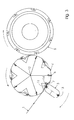
- Fig. 1 shows a schematic side view of an embodiment of a folder with variable section length, a knife cylinder 3, a transfer cylinder 4 and one Folding jaw cylinder 5 includes.
- the knife cylinder 3 has cutting knives 13 around a web strand 1 in signatures desired length to cut.
- the transfer cylinder 4 has cutting strips 11, which with the cutting knives 13 of the knife cylinder 3 for cutting the web strand 1 work together.
- At the periphery of the transfer cylinder 4 are for holding the Signature gripper 7 arranged.
- the transfer cylinder 4 has adjustable Diameter sections which are arranged on its periphery.
- everybody adjustable Diameter section can adjust the size of a section of the transfer cylinder 4.
- the adjustable Diameter sections can e.g. be designed as adjustable rollers 9. As the Arrows in the adjustable rollers 9 can show each adjustable roller 9 Adjusting means 15, e.g.
- a winch e.g. an eccentric winch or a linear winch
- Fig. 1 shows how the size of the adjustable parts of the transfer cylinder can be adjusted by the adjustable rollers 9 are withdrawn or extended, that is, in which the adjustable rollers 9 on the central axis 12 of the transfer cylinder 4 to and from it are moved to reduce the adjustable portions of the transfer cylinder 4 or enlarge.
- the transfer cylinder 4 is provided along its periphery with folding knives 6 and a Folding jaw cylinder 5 is provided with folding jaws 8 along its periphery.
- the Folding knife 6 on the transfer cylinder 4 act with the folding flaps 8 on the Folder cylinder 5 together by folding the signature into the jaws 8.
- a dancer roller 2 is located in an area in which the web strand 1 in the Section of the device occurs where the signatures are cut.
- the Dancer roller 2 compensates for differences in the length of the web strand, e.g. Differences, caused by setting the effective diameter of the transfer cylinder 4 be out.
- Fig. 2 shows a schematic side view of the folder with variable section length of Fig. 1, which is set to produce a shorter signature.
- the adjustable Rollers 9 are retracted, i.e. in the direction of the central axis 12 of the transfer cylinder 4 moves to the effective diameter of some sections of the transfer cylinder 4 reduce and thus reduce the signature length. Make the dash-dotted lines the positions of the adjustable rollers 9 to produce longer signatures.
- Fig. 2 shows an example of the dimensions of the transfer cylinder 4.
- the diameter the transfer cylinder 4 is e.g. 1000 mm and the diameter of the adjustable Rolling is 101.764 mm.
- the adjustable roller 9 is set so that it cuts shorter signatures, the length of a connecting line between one Cutting bar 11 and a folding knife 6 e.g. 318,797 mm. In this case runs the connecting line between the cutting bar and the folding knife in the Essentially straight forward.
- the adjustable roller 9 is set so that the Device cuts longer signatures, the length of the connecting line is between a cutting bar 11 and a folding knife 6 e.g. 334.855 mm.
- the Total length of 334.855 mm is the sum of the three lengths 155.285 mm, 34.192 mm and 145,378 mm.
- the length difference of the connecting line between the Folding knife 6 and the cutting bar 11 is thus 16,058 mm.
- the operation of the folder with variable section length is illustrated by the figures 1 and 2 explained.
- the web strand 1 is passed around the dancer roll 2 and then enters the Section of the knife cylinder 3 and the transfer cylinder 4, in which the signatures get cut.
- the dancer roller 2 allows differences in the length of the web strand be compensated by the transfer cylinder 4.
- the differences are caused through the adjustable roller 9 on the transfer cylinder 4, if this for longer Sections is set.
- the knife cylinder 3 and the transfer cylinder 4 rotate in opposite direction, so that the cutting knife 13 of the knife cylinder during the rotation of the cylinders meet the cutting bars of the transfer cylinder 4.
- the Web strand 1 is held on the transfer cylinder 4 with the aid of a gripper 7.
- the adjustable roller 9 is like this attached that the effective diameter of the transfer cylinder 4 in the range between the folding knife 6 and the cutting bar 11 or the gripper 7 of the desired Signature length corresponds.
- the grippers or pin needles 7 on the transfer cylinder 4th give the signature hold.
- the transfer cylinder 4 then rotates to the signature in the Folding jaw cylinder 5 to transport and the folding knife 6 folds the signature in the Folding flap 8.
- the difference in the signature length results from the length of the Connection line between the gripper 7 and the associated folding knife 6. Die Dimensions that have been described with reference to FIG. 2 show an example a possible difference in signature length or book length that way can be adjusted.
- Fig. 3 shows a schematic side view of a second embodiment of a Folder with variable section length for the production of longer signatures.
- the corresponding elements of the different embodiments are each with Identical reference numerals.
- Fig. 3 shows a knife cylinder 3, which on the Transfer cylinder 4 can be moved to or away from the transfer cylinder 4.
- the Transfer cylinder or folding knife cylinder 4 is along its periphery Cutting bars 11 and grippers 7 equipped.
- the grippers 7 are on the gripper shafts 14 arranged.
- the grippers 7 and the cutting strips 11 can together on the central axis 12 of the transfer cylinder 4 to be moved to or away from it to the effective Set the diameter of a section of the transfer cylinder 4.
- Fig. 3 shows a schematic side view of a second embodiment of a Folder with variable section length for the production of longer signatures.
- the corresponding elements of the different embodiments are each with Identical reference numerals.
- Fig. 3 shows a knife cylinder 3, which on the Transfer
- FIG. 3 shows the Position of the cutting bar 11 and the gripper 7 in a retracted position Production of shorter signatures.
- the knife cylinder 3 is on the transfer cylinder 4 moves so that the cutting knives 13 of the knife cylinder 3 cut the cutting strips 11 contact during the cutting process. If a longer signature is desired, the cutting bars 11 together with the grippers 7 to the outside, from the central axis 12 of the transfer cylinder 4 moves away, so that the effective diameter of sections of the transfer cylinder 4 is enlarged.
- Fig. 4 shows the extended position of the grippers or pin needles 7 and the cutting strips 11 for the production of longer signatures. The knife cylinder 3 is moved away from the transfer cylinder 4 to with the Cutting bars 11 cooperate.
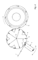
- Fig. 5 shows a cross-sectional view of the folder with variable section length of Fig. 3.
- Fig. 5 shows the cutting strips 11 and the grippers 7 in a retracted position Position for producing shorter signatures.
- the cutting bars 11 and the grippers 7 have been moved in the direction of the central axis 12 of the transfer cylinder.
- the Knife cylinder 3 has been moved towards the transfer cylinder 4, so that the Cutting knife 13 of the knife cylinder 3, the cutting strips 11 during the Contact the cutting process.
- Fig. 5 shows the dimensions of the transfer cylinder 4. Der The diameter of the transfer cylinder 4 is e.g. 1000 mm.
- the length of the web strand 1 from the cutting bar 11 to the next folding knife 6 is e.g. 299.47 mm. this is the Sum of the straight connecting line, the length of e.g. Is 258.11 mm, and the curved connecting line, the length of e.g. Is 41.36 mm, as shown in FIG. 5.
- Fig. 6 shows a cross-sectional view of the folder with variable section length of Fig. 4.
- the cutting bars 11 and the grippers 7 are in an extended position Position for making longer signatures.
- the knife cylinder 3 is from Transfer cylinder 4 has been moved away, so that the cutting knife 13 of the Knife cylinder 3 touch the cutting bars 11 during the cutting process.
- the diameter of the transfer cylinder 4 is e.g. 1000 mm.
- the length of the web strand 1 from the cutting bar 11 to the next folding knife 6 is 310.02 mm. this is the Sum of the straight connecting line, the length of which is 283.19 mm, and the curved connecting line, the length of which is 26.83 mm, as shown in FIG. 6.
Landscapes
- Life Sciences & Earth Sciences (AREA)
- Forests & Forestry (AREA)
- Engineering & Computer Science (AREA)
- Mechanical Engineering (AREA)
- Folding Of Thin Sheet-Like Materials, Special Discharging Devices, And Others (AREA)
- Nonmetal Cutting Devices (AREA)
- Making Paper Articles (AREA)
- Preliminary Treatment Of Fibers (AREA)
Abstract
Description
Die vorliegende Erfindung betrifft eine Schneidevorrichtung mit variabler Abschnittslänge
zum Schneiden eines Bahnstrangs in Signaturen von gewünschter Länge, insbesondere in
einem Falzapparat einer Rollenrotationsdruckmaschine, gemäß dem Oberbegriff von
Anspruch 1.The present invention relates to a cutting device with variable section length
for cutting a web strand in signatures of the desired length, especially in
a folder of a web-fed rotary printing press, according to the preamble of
Rollenrotationsdruckmaschinen haben in der Regel einen dem Druckwerk nachgeordneten Falzapparat. Der Falzapparat schneidet und falzt eine Papierbahn oder einen Bahnstrang, um eine Signatur oder einen Bogen von bestimmter Länge herzustellen.Web-fed rotary printing presses usually have a subordinate to the printing unit Folder. The folder cuts and folds a paper web or web strand, to create a signature or sheet of a certain length.
Bekannte Falzapparate mit variabler Abschnittslänge sind in der Regel in zwei Kategorien eingeteilt. Bei der ersten Kategorie wird die Größe oder Länge der Signaturen verändert, indem Teile des Falzapparats, wie z.B. der Sammelzylinder, der Messerzylinder oder der Falzklappenzylinder ausgetauscht werden. Diese Lösung hat den Nachteil, dass sie kostenintensiv und zeitaufwendig ist, da es beträchtliche Zeit braucht, einzelne Teile des Falzapparats auszutauschen.Known folders with variable section lengths are usually in two categories assigned. The first category changes the size or length of the signatures, by parts of the folder, e.g. the collecting cylinder, the knife cylinder or the The jaw cylinder can be replaced. The disadvantage of this solution is that it is costly and time consuming as it takes considerable time to separate parts of the To replace the folder.
Bei der zweiten Kategorie der Falzapparate mir variabler Abschnittslänge wird die Winkelgeschwindigkeit des Messerzylinders relativ zur Geschwindigkeit des Bahnstrangs erhöht und hierdurch die Signatur beschleunigt, um die Vorderkante der Signatur in die gewünschte Position auf einem Übergabezylinder zu bringen. Der Nachteil dieser Technik liegt in der Differenz der Geschwindigkeit des Messerzylinders zu der des Bahnstrangs. Bei dieser Technik muss die Umfangsgeschwindigkeit des Messerzylinders gleich hoch oder höher als die Geschwindigkeit des Bahnstrangs sein. Wenn jedoch die Umfangsgeschwindigkeit des Messerzylinders beträchtlich höher als die Geschwindigkeit des Bahnstrangs ist, um eine möglichst kürze Signaturlänge zu erreichen, nimmt die Qualität des Schnitts ab.In the second category of folders with variable section length, the Angular speed of the knife cylinder relative to the speed of the web strand increased and thereby accelerated the signature to the front edge of the signature in the to bring the desired position on a transfer cylinder. The disadvantage of this technique lies in the difference between the speed of the knife cylinder and that of the web strand. At this technique, the peripheral speed of the knife cylinder must be the same or be higher than the speed of the web strand. However, if the Circumferential speed of the knife cylinder considerably higher than the speed of the web strand in order to achieve the shortest possible signature length Quality of the cut.
Die Transportgeschwindigkeit der Signaturen nach dem Schnitt entspricht der der Umfangsgeschwindigkeit des Messerzylinders. Wenn die Umfangsgeschwindigkeit des Messerzylinders relativ zur Geschwindigkeit des Bahnstrangs erhöht wird, muss die Geschwindigkeit der Signaturen ebenfalls im Verhältnis zu der Geschwindigkeit des Bahnstrang erhöht werden. Dies erfordert, dass die Signaturen auf eine neue, höhere Geschwindigkeit beschleunigt werden. Die Beschleunigung der Signaturen kann dazu führen, dass sich die Position der Signaturen verändert. Diese Veränderung der Position der Signaturen kann zu einer Beeinträchtigung der Qualität der Signaturen sowie der Leistung des Schneidesystems führen und somit die Leistung des gesamten Falzapparats mindern.The speed of transport of the signatures after the cut corresponds to that of Circumferential speed of the knife cylinder. If the peripheral speed of the Knife cylinder is increased relative to the speed of the web strand, the Speed of the signatures also in relation to the speed of the Web strand to be increased. This requires the signatures to be new, higher Speed can be accelerated. This can be accelerated by the signatures cause the position of the signatures to change. This change in the position of the Signatures can affect the quality of the signatures as well as the performance of the cutting system and thus reduce the performance of the entire folder.
Ein einstellbarer Falzapparat für Rollenrotationsdruckmaschinen ist in der GB 1,214,339 beschrieben. Der variable Falzapparat ist mit einem Messerzylinder ausgestattet, der mit einem Übergabezylinder zusammenwirkt. Zwischen dem Messerzylinder und dem Übergabezylinder ist ein Spalt gebildet, durch den die Bahn hindurch geführt wird. Der Übergabezylinder trägt um seinen Umfang herum Bahnerfassungselemente, die jeweils einen Greifer zum Erfassen der Vorderkante einer aus dem Spalt austretenden Bahn, ein Falzmesser, das mit einer Falzklappe in einem dritten Zylinder zusammenwirkt und eine Stützfläche umfassen, die mit dem zugeordneten Messer des Messerzylinders zusammenwirkt. Die Winkellage des Greifers und des Falzmessers sind an der Rotationsachse der Übergabezylinders im Verhältnis zu der Winkellage der Stützfläche verstellbar, um die Bogengröße verändern zu können.An adjustable folder for web-fed rotary printing presses is in GB 1,214,339 described. The variable folder is equipped with a knife cylinder, which with cooperates with a transfer cylinder. Between the knife cylinder and the Transfer cylinder is formed a gap through which the web is passed. The Transfer cylinder carries web sensing elements around its circumference, each a gripper for grasping the leading edge of a web emerging from the gap Folding knife that interacts with a folding flap in a third cylinder and one Include support surface with the associated knife of the knife cylinder cooperates. The angular position of the gripper and the folding knife are at the Axis of rotation of the transfer cylinder in relation to the angular position of the support surface adjustable to change the sheet size.
Die DE 39 34 673 C2 beschreibt eine in der Formatlänge verstellbare Querschneidvorrichtung für laufende Bahnen. Eine Bahn verläuft zwischen einem Messerzylinder und einem zugeordneten Zylinder gleichen Durchmessers. Der Messerzylinder ist an seiner Peripherie mit Schneidmessern ausgestattet. Der ihm zugeordnete Zylinder trägt elastische Schneidleisten, die mit den Schneidmessern am Messerzylinder zum Schneiden der Bahn zusammenwirken. Die Schneidmesser und die Schneidleisten sind um Schwenkachsen herum schwenkbar gelagert. Die Schwenkachsen liegen in den Zylindern und sind parallel zu den Zylinderachsen angeordnet. Während eines Schneidvorgangs werden die Schneidmesser und die Schneidleisten in der Weise verschwenkt, dass sie sich entgegen der Bahnlaufrichtung bewegen. Ein Nachteil der in der DE 39 34 673 C2 beschriebenen in der Formatlänge verstellbaren Querschneidvorrichtung liegt darin, dass ein eher komplizierter Schwenkmechanismus benötigt wird, weil die Bewegung der Schneidmesser und der Schneidleisten bei jedem Schneidvorgang synchron verlaufen muss.DE 39 34 673 C2 describes an adjustable in the format length Cross cutting device for running webs. A path runs between one Knife cylinder and an associated cylinder of the same diameter. The Knife cylinder is equipped with cutting knives on its periphery. The him assigned cylinder carries elastic cutting strips, which with the cutting knives Knife cylinders work together to cut the web. The cutting knives and the Cutting bars are pivoted around swivel axes. The swivel axes lie in the cylinders and are arranged parallel to the cylinder axes. During one Cutting process, the cutting knives and the cutting bars are in the way pivots that they move against the direction of web travel. A disadvantage of that in the DE 39 34 673 C2 described cross-cutting device adjustable in format length is that a more complicated swivel mechanism is needed because the Movement of the cutting knives and the cutting bars synchronously with each cutting process must run.
Ein Artikel mit dem Titel "Goss Exhibits Futuristic Concept Press" von Gerry Valerio, beschreibt den Gebrauch einer abnehmbaren, nahtlosen Ummantelung eines Messerzylinders mittels derer eine variable Abschnittslänge erreicht werden kann. Die Abschnittslänge wird verändert, indem eine Ummantelung von dem Messerzylinder abgenommen und eine andere dickere oder dünnere Ummantelung angebracht wird. Um die Veränderungen im Durchmesser des Zylinders auszugleichen, muss die Position der Zylinder zueinander ebenfalls angeglichen werden. Ein Nachteil beim Verwenden von austauschbaren Ummantelungen ist, dass für jede gewünschte Abschnittslänge eine andere Ummantelung benötigt wird.An article entitled "Goss Exhibits Futuristic Concept Press" by Gerry Valerio, describes the use of a removable, seamless sheath Knife cylinder by means of which a variable section length can be achieved. The Section length is changed by a sheath from the knife cylinder removed and another thicker or thinner casing is attached. Around To compensate for the changes in the diameter of the cylinder, the position of the Cylinders can also be adjusted to each other. A disadvantage when using Interchangeable sheathing is different for each section length you want Sheathing is needed.
Es ist eine Aufgabe der vorliegenden Erfindung eine Schneidevorrichtung zum Schneiden eines Bahnstrangs in Signaturen von gewünschter Länge zu schaffen, die die obengenannten Nachteile der bisher bekannten Vorrichtungen dieser Art vermeidet und das Schneiden von Signaturen von verschiedener Länge ermöglicht, ohne dass die Arbeitsgeschwindigkeit der Vorrichtung angepasst werden muss und ohne dass Teile der Vorrichtung ausgetauscht werden müssen.It is an object of the present invention to provide a cutting device for cutting to create a web strand in signatures of the desired length, which the Avoids the above-mentioned disadvantages of the previously known devices of this type and that Allows you to cut signatures of different lengths without the need for Working speed of the device must be adjusted and without parts of the Device need to be replaced.
Es ist insbesondere eine Aufgabe der vorliegenden Erfindung einen Falzapparat mit
variabler Abschnittslänge zu schaffen, der das Schneiden von verschiedenen
Signaturlängen ermöglicht, wobei der Übergabezylinder der Vorrichtung die Kontrolle
über die Vorderkante der Signatur hat, ohne dass die Geschwindigkeit des
Übergabezylinders angepasst werden muss, und ohne dass Teile der Vorrichtung
ausgetauscht werden müssen.In particular, it is an object of the present invention to provide a variable section length folder which enables the cutting of different signature lengths, the transfer cylinder of the device being in control of the leading edge of the signature without the speed of the
Transfer cylinder must be adjusted, and without parts of the device must be replaced.
Diese Aufgabe wird erfindungsgemäß durch die Merkmale von Anspruch 1 gelöst. Weitere
Merkmale der Erfindung sind in den Unteransprüchen beschrieben. This object is achieved by the features of
Eine erfindungsgemäße Schneidevorrichtung mit variabler Abschnittslänge umfasst einen Messerzylinder und einen eine Mittelachse und eine Peripherie aufweisenden Übergabezylinder, der derart ausgebildet ist, dass er mit dem Messerzylinder zusammenwirkt, um einen Bahnstrang in Signaturen von gewünschter Länge zu schneiden.A cutting device according to the invention with variable section length comprises one Knife cylinder and one having a central axis and a periphery Transfer cylinder, which is designed such that it with the knife cylinder cooperates to cut a web strand into signatures of the desired length.
Der Übergabezylinder weist an seiner Peripherie einen Abschnitt veränderbaren Durchmessers, nachfolgend auch verstellbarer oder veränderbarer Durchmesserabschnitt genannt, auf, wobei der verstellbare Durchmesserabschnitt mit dem Übergabezylinder verbunden, bzw. an diesem angeordnet ist und in Richtung auf die Zylindermittelachse zu und von der Zylindermittelachse weg bewegbar ist, um die gewünschte Länge der Signaturen einzustellen.The transfer cylinder has a section that can be changed on its periphery Diameter, subsequently also adjustable or changeable diameter section called, on, wherein the adjustable diameter section with the transfer cylinder connected, or is arranged on this and in the direction of the cylinder central axis and is movable away from the cylinder center axis by the desired length of the Set signatures.
Die erfindungsgemäße Schneidevorrichtung besitzt den Vorteil, dass sie leicht auf verschiedene Signaturlängen einstellbar ist, ohne dass Teile der Schneidevorrichtung ausgetauscht werden müssen.The cutting device according to the invention has the advantage that it is easy to open Different signature lengths can be set without parts of the cutting device need to be replaced.
Gemäß einem weiteren Merkmal der Erfindung ist der verstellbare Durchmesserabschnitt eine verstellbare Walze, z.B. mit einem Durchmesser im Bereich zwischen 5 und 20 cm, die in Richtung auf die Zylindermittelachse zu und von der Zylindermittelachse weg bewegbar ist.According to a further feature of the invention, the adjustable diameter section an adjustable roller, e.g. with a diameter in the range between 5 and 20 cm, that towards and away from the cylinder center axis is movable.
Gemäß einem weiteren Merkmal der Erfindung ist an dem verstellbaren Durchmesserabschnitt eine Hebe- und Senkvorrichtung, z.B. ein Pneumatikzylinder, eine Winde, z.B. eine lineare Winde und/oder eine Exzenterwinde, oder auch ein Zahnstangen basierter Hebe- und Senkmechanismus angebracht, mittels welcher der verstellbare Durchmesserabschnitt auf die Zylindermittelachse zu und von der Zylindermittelachse weg bewegt werden kann.According to a further feature of the invention is on the adjustable Diameter section of a lifting and lowering device, e.g. one pneumatic cylinder, one Winch e.g. a linear winch and / or an eccentric winch, or a rack based lifting and lowering mechanism attached, by means of which the adjustable Diameter section towards the cylinder center axis to and from the cylinder center axis can be moved.
In Übereinstimmung mit einem weiteren Merkmal der Erfindung sind ein Greifer und ein Falzmesser an der Peripherie des Übergabezylinders in einem vorgegebenem Abstand von der Zylindermittelachse mit dem Übergabezylinder verbunden, wobei der verstellbare Durchmesserabschnitt zwischen dem Greifer und dem Falzmesser angeordnet ist. Das hat den Vorteil, dass der Messerzylinder im Hinblick auf den Übergabezylinder in einer vorgegebenen Position bleiben kann, auch wenn der verstellbare Durchmesserabschnitt auf den Mittelpunkt des Übergabezylinders zu oder von ihm weg bewegt wird.In accordance with another feature of the invention, a gripper and a Folding knife on the periphery of the transfer cylinder at a predetermined distance of the cylinder center axis connected to the transfer cylinder, the adjustable Diameter section between the gripper and the folding knife is arranged. That has the advantage that the knife cylinder with respect to the transfer cylinder in one predetermined position can remain, even if the adjustable diameter section on the center of the transfer cylinder is moved to or away from it.
Gemäß einer weiteren Ausführungsform der Erfindung ist am Messerzylinder ein Schneidmesser angeordnet, welches mit einer an der Peripherie des Übergabezylinders angeordneten Schneidleiste zusammenwirkt und die Materialbahn in Signaturen zerschneidet, wenn der Messerzylinder und der Übergabezylinder synchron zueinander rotieren.According to a further embodiment of the invention, a is on the knife cylinder Cutting knife arranged, which with a on the periphery of the transfer cylinder arranged cutting bar interacts and the material web in signatures cuts when the knife cylinder and the transfer cylinder synchronously with each other rotate.
In Übereinstimmung mit einem zusätzlichen Merkmal der Erfindung hat der Übergabezylinder eine konstante Winkelgeschwindigkeit, woraus sich der Vorteil ergibt, dass eine komplizierte Kontrolle der Drehgeschwindigkeit des Übergabezylinders nicht notwendig ist.In accordance with an additional feature of the invention, the Transfer cylinder a constant angular velocity, which gives the advantage that complicated control of the speed of rotation of the transfer cylinder is not necessary is.
Gemäß einer weiteren Ausführungsform der Erfindung sind mit dem verstellbaren Durchmesserabschnitt jeweils ein Greifer und eine Schneidleiste verbunden. Der Greifer und die Schneidleiste sind vorzugsweise zusammen mit dem verstellbaren Durchmesserabschnitt auf die Zylindermittelachse zu und von ihr weg bewegbar.According to a further embodiment of the invention, the adjustable Diameter section each connected to a gripper and a cutting bar. The gripper and the cutting bar are preferably together with the adjustable Diameter section movable towards and away from the cylinder central axis.
Ein erfindungsgemäßer Falzapparat mit variabler Abschnittslänge umfasst einen Messerzylinder sowie einen Übergabezylinder, der in der Weise ausgebildet ist und mit dem Messerzylinder zusammenwirkt, dass ein auf ihm geführter Bahnstrang in Signaturen von gewünschter Länge geschnitten wird. Der Übergabezylinder besitzt eine Zylindermittelachse und eine Peripherie und weist einen verstellbaren Durchmesserabschnitt auf, der vorzugsweise an der Peripherie des Übergabezylinders angeordnet ist. Der verstellbare Durchmesserabschnitt ist vorzugsweise mit dem Übergabezylinder verbunden und ist in Richtung auf die Zylindermittelachse zu, bzw. von dieser weg bewegbar, um eine gewünschte Abschnittslänge der Signaturen einzustellen. Der erfindungsgemäße Falzapparat umfasst ferner einen Falzklappenzylinder, der einen Zylindermantel mit einer daran angeordneten Falzklappe aufweist, welche mit einem an der Peripherie des Übergabezylinders angeordneten Falzmesser in der Weise zusammenwirkt, das die Signaturen in der Falzklappe durch Zusammenwirkung mit dem Falzmesser gefalzt werden.A folder of the invention with a variable section length comprises one Knife cylinder and a transfer cylinder, which is designed in such a way and with the knife cylinder cooperates that a web strand guided on it in signatures is cut to the desired length. The transfer cylinder has one Cylinder center axis and a periphery and has an adjustable Diameter section on which is preferably on the periphery of the transfer cylinder is arranged. The adjustable diameter section is preferably with the Transfer cylinder connected and is in the direction of the cylinder center axis to, or from this can be moved away in order to set a desired section length of the signatures. The folder according to the invention further comprises a folder cylinder, the one Has cylinder jacket with a folding flap arranged thereon, which with one on the Periphery of the transfer cylinder arranged folding knife cooperates in such a way that the signatures in the folding flap are folded by interaction with the folding knife become.
Der Begriff Bahnstrang schließt in diesem Zusammenhang eine beliebige Art von bahnförmigem Material ein, wie z.B. eine Papierbahn oder einen Papierbahnstrang. Der Begriff Signatur bezeichnet dabei einen beliebigen Abschnitt Material, der von dem bahnförmigen Material abgetrennt wird, wie z.B. ein Bogen Papier.In this context, the term train strand includes any type of sheet material such as e.g. a paper web or a paper web strand. The The term "signature" refers to any section of material from the sheet material is separated, e.g. a sheet of paper.
Weitere Merkmale der Erfindung ergeben sich aus den Unteransprüchen.Further features of the invention emerge from the subclaims.
Die Konstruktion und Arbeitsweise der Erfindung sowie ihre zusätzlichen Aufgaben und Vorteile werden nachfolgend mit Bezug auf die Zeichnungen beschrieben. In den Zeichnungen zeigen:
- Fig. 1
- eine schematische Seitenansicht einer ersten Ausführungsform eines erfindungsgemäßen Falzapparats mit variabler Abschnittslänge, der zur Herstellung von längeren Signaturen eingestellt ist;
- Fig. 2
- eine schematische Seitenansicht des Falzapparats mit variabler Abschnittslänge nach Fig. 1, der zur Herstellung von kürzeren Signaturen eingestellt ist;
- Fig. 3
- eine schematische Seitenansicht einer zweiten Ausführungsform eines erfindungsgemäßen Falzapparats mit variabler Abschnittslänge, der zur Herstellung von kürzeren Signaturen eingestellt ist;
- Fig. 4
- eine schematische Seitenansicht des Falzapparats mit variabler Abschnittslänge nach Fig. 3, der zur Herstellung von längeren Signaturen eingestellt ist;
- Fig. 5
- einen Querschnittsansicht des in Fig. 3 dargestellten Falzapparats mit variabler Abschnittslänge; und
- Fig. 6
- zeigt einen Querschnittsansicht des in Fig. 4 dargestellten Falzapparats mit variabler Abschnittslänge.
- Fig. 1
- a schematic side view of a first embodiment of a folder according to the invention with variable section length, which is set to produce longer signatures;
- Fig. 2
- a schematic side view of the folder with variable section length of Figure 1, which is set to produce shorter signatures.
- Fig. 3
- is a schematic side view of a second embodiment of a folder of the invention with variable section length, which is set to produce shorter signatures;
- Fig. 4
- is a schematic side view of the folder with variable section length of Figure 3, which is set to produce longer signatures.
- Fig. 5
- a cross-sectional view of the folder shown in Figure 3 with variable section length. and
- Fig. 6
- shows a cross-sectional view of the folder with variable section length shown in Fig. 4.
Fig. 1 zeigt eine schematische Seitenansicht einer Ausführungsform eines Falzapparats mit
variabler Abschnittslänge, der einen Messerzylinder 3, einen Übergabezylinder 4 und einen
Falzklappenzylinder 5 umfasst.Fig. 1 shows a schematic side view of an embodiment of a folder with
variable section length, a
Der Messerzylinder 3 hat Schneidmesser 13, um einen Bahnstrang 1 in Signaturen einer
gewünschten Länge zu schneiden. Der Übergabezylinder 4 hat Schneidleisten 11, die mit
den Schneidmessern 13 des Messerzylinders 3 zum Schneiden des Bahnstrangs 1
zusammenwirken. An der Peripherie des Übergabezylinders 4 sind zum Halten der
Signaturen Greifer 7 angeordnet. Der Übergabezylinder 4 verfügt über verstellbare
Durchmesserabschnitte, die an seiner Peripherie angeordnet sind. Jeder verstellbare
Durchmesserabschnitt kann die Größe eines Abschnitts des Übergabezylinders 4 anpassen.
Somit sind die effektiven Durchmesser des Übergabezylinders 4 und des Messerzylinders 3
zur Herstellung von Signaturen von variabler Abschnittslänge geeignet. Die verstellbaren
Durchmesserabschnitte können z.B. als verstellbare Walzen 9 ausgebildet sein. Wie die
Pfeile in den verstellbaren Walzen 9 zeigen, kann jede verstellbare Walze 9 durch
Stellmittel 15, z.B. eine Winde, wie z.B. eine Exzenterwinde oder eine lineare Winde, oder
durch eine beliebige andere geeignete Einstellvorrichtung bewegt werden. Fig. 1 zeigt, wie
die Größe der verstellbaren Teile des Übergabezylinders angepasst werden kann, indem die
verstellbaren Walzen 9 zurückgezogen oder ausgefahren werden, also in dem die
verstellbaren Walzen 9 auf die Mittelachse 12 des Übergabezylinders 4 zu und von ihr weg
bewegt werden, um die verstellbaren Abschnitte des Übergabezylinders 4 zu verkleinern
bzw. zu vergrößern.The
Der Übergabezylinder 4 ist entlang seiner Peripherie mit Falzmessern 6 versehen und ein
Falzklappenzylinder 5 ist entlang seiner Peripherie mit Falzklappen 8 versehen. Die
Falzmesser 6 auf dem Übergabezylinder 4 wirken mit den Falzklappen 8 auf dem
Falzklappenzylinder 5 zusammen, indem sie die Signatur in die Falzklappen 8 falzen.The
Eine Tänzerwalze 2 befindet sich in einem Bereich, in dem der Bahnstrang 1 in den
Abschnitt der Vorrichtung eintritt, in dem die Signaturen geschnitten werden. Die
Tänzerwalze 2 gleicht Unterschiede in der Länge des Bahnstrangs, wie z.B. Unterschiede,
die durch das Einstellen des effektiven Durchmessers des Übergabezylinders 4 verursacht
werden, aus.A
Fig. 2 zeigt eine schematische Seitenansicht des Falzapparats mit variabler Abschnittslänge
von Fig. 1, der zur Herstellung einer kürzeren Signatur eingestellt ist. Die verstellbaren
Walzen 9 sind zurückgezogen, d.h. in Richtung der Mittelachse 12 des Übergabezylinders
4 bewegt, um den effektiven Durchmesser einiger Abschnitte des Übergabezylinders 4 zu
verkleinern und somit die Signaturlänge zu verringern. Die strichpunktierten Linien stellen
die Positionen der verstellbaren Walzen 9 zur Herstellung von längeren Signaturen dar.Fig. 2 shows a schematic side view of the folder with variable section length
of Fig. 1, which is set to produce a shorter signature. The
Fig. 2 zeigt ein Beispiel für die Abmessungen des Übergabezylinders 4. Der Durchmesser
des Übergabezylinders 4 beträgt z.B. 1000 mm und der Durchmesser der verstellbaren
Walzen ist 101,764 mm. Wenn die verstellbare Walze 9 so eingestellt wird, dass sie
kürzere Signaturen schneidet, kann die Länge einer Verbindungslinie zwischen einer
Schneidleiste 11 und einem Falzmesser 6 z.B. 318.797 mm betragen. In diesem Fall
verläuft die Verbindungslinie zwischen der Schneidleiste und dem Falzmesser im
Wesentlichen geradlinig. Wenn die verstellbare Walze 9 so eingestellt wird, dass die
Vorrichtung längere Signaturen schneidet, beträgt die Länge der Verbindungslinie
zwischen einer Schneidleiste 11 und einem Falzmesser 6 z.B. 334.855 mm. Die
Gesamtlänge von 334.855 mm ist die Summe aus den drei Längen 155.285 mm, 34.192
mm und 145.378 mm. Der Längenunterschied der Verbindungslinie zwischen dem
Falzmesser 6 und der Scheidleiste 11 beträgt also 16.058 mm.Fig. 2 shows an example of the dimensions of the
Die Arbeitsweise des Falzapparats mit variabler Abschnittslänge wird anhand der Figuren
1 und 2 erklärt. Der Bahnstrang 1 wird um die Tänzerwalze 2 geleitet und tritt dann in den
Abschnitt des Messerzylinders 3 und des Übergabezylinders 4 ein, in dem die Signaturen
geschnitten werden. Die Tänzerwalze 2 lässt Unterschiede in der Bahnstranglänge zu, die
vom Übergabezylinder 4 ausgeglichen werden. Die Unterschiede werden hervorgerufen
durch die verstellbaren Walze 9 auf dem Übergabezylinder 4, wenn diese auf längere
Abschnitte eingestellt wird. Der Messerzylinder 3 und der Übergabezylinder 4 rotieren in
entgegengesetzter Richtung, so dass die Schneidmesser 13 des Messerzylinders während
der Rotation der Zylinder auf die Schneidleisten des Übergabezylinders 4 treffen. Der
Bahnstrang 1 wird mit Hilfe eines Greifers 7 auf dem Übergabezylinder 4 gehalten.
Während der Übergabezylinder 4 entgegen dem Uhrzeigersinn rotiert, wird der Bahnstrang
an der Peripherie des Übergabezylinders 4 entlang geführt. Die verstellbare Walze 9 ist so
angebracht, dass der effektive Durchmesser des Übergabezylinders 4 in dem Bereich
zwischen dem Falzmesser 6 und der Schneidleiste 11 oder dem Greifer 7 der gewünschten
Signaturlänge entspricht. Die Greifer oder auch Punkturnadeln 7 am Übergabezylinder 4
geben der Signatur Halt. Der Übergabezylinder 4 rotiert dann, um die Signatur in den
Falzklappenzylinder 5 zu transportieren und das Falzmesser 6 falzt die Signatur in die
Falzklappe 8. Der Unterschied in der Signaturlänge ergibt sich aus der Länge der
Verbindungslinie zwischen dem Greifer 7 und dem damit verbundenen Falzmesser 6. Die
Maßangaben, die anhand der Fig. 2 beschrieben wurden, zeigen anhand eines Beispiels
einen möglichen Unterschied in der Signaturlänge oder der Buchlänge, der auf diese Weise
eingestellt werden kann.The operation of the folder with variable section length is illustrated by the figures
1 and 2 explained. The
Fig. 3 zeigt eine schematische Seitenansicht einer zweiten Ausführungsform eines
Falzapparats mit variabler Abschnittslänge zur Herstellung von längeren Signaturen. Die
entsprechenden Elemente der verschiedenen Ausführungsformen sind jeweils mit
identischen Bezugszeichen bezeichnet. Fig. 3 zeigt einen Messerzylinder 3, der auf den
Übergabezylinder 4 zu oder von dem Übergabezylinder 4 weg bewegt werden kann. Der
Übergabezylinder oder Falzmesserzylinder 4 ist entlang seiner Peripherie mit
Schneidleisten 11 und Greifern 7 ausgestattet. Die Greifer 7 sind auf den Greiferwellen 14
angeordnet. Die Greifer 7 und die Schneidleisten 11 können zusammen auf die Mittelachse
12 der Übergabezylinders 4 zu oder von ihr weg bewegt werden, um den effektiven
Durchmesser eines Abschnitts des Übergabezylinders 4 einzustellen. Fig. 3 zeigt die
Position der Schneidleiste 11 und des Greifers 7 in einer zurückgezogenen Position zur
Herstellung von kürzeren Signaturen. Der Messerzylinder 3 wird auf den Übergabezylinder
4 zu bewegt, so dass die Schneidmesser13 des Messerzylinders 3 die Schneidleisten 11
während des Schneidvorgangs kontaktieren. Wird eine längere Signatur gewünscht, werden
die Schneidleisten 11 zusammen mit den Greifern 7 nach außen, von der Mittelachse 12
des Übergabezylinders 4 weg bewegt, so dass der effektiver Durchmesser von Abschnitten
des Übergabezylinders 4 vergrößert wird. Fig. 4 zeigt die ausgefahrene Position der Greifer
oder Punkturnadeln 7 und der Schneidleisten 11 zur Herstellung von längeren Signaturen.
Der Messerzylinder 3 wird vom Übergabezylinder 4 weg bewegt, um mit den
Schneidleisten 11 zusammenzuwirken.Fig. 3 shows a schematic side view of a second embodiment of a
Folder with variable section length for the production of longer signatures. The
corresponding elements of the different embodiments are each with
Identical reference numerals. Fig. 3 shows a
Fig. 5 zeigt eine Querschnittsansicht des Falzapparats mit variabler Abschnittslänge von
Fig. 3. Fig. 5 zeigt die Schneidleisten 11 und die Greifer 7 in einer zurückgezogenen
Position zur Herstellung von kürzeren Signaturen. Die Schneidleisten 11 und die Greifer 7
sind in Richtung der Mittelachse 12 des Übergabezylinders bewegt worden. Der
Messerzylinder 3 ist auf den Übergabezylinder 4 zu bewegt worden, so dass die
Schneidmesser 13 des Messerzylinders 3 die Schneidleisten 11 während des
Schneidvorgangs kontaktieren. Fig. 5 zeigt die Ausmaße des Übergabezylinders 4. Der
Durchmesser des Übergabezylinders 4 beträgt z.B. 1000 mm. Die Länge des Bahnstrangs 1
von der Schneidleiste 11 zum nächsten Falzmesser 6 beträgt z.B. 299,47 mm. Dies ist die
Summe der geraden Verbindungslinie, deren Länge z.B. 258,11 mm beträgt, und der
gebogenen Verbindungslinie, deren Länge z.B. 41,36 mm beträgt, wie Fig. 5 zeigt.Fig. 5 shows a cross-sectional view of the folder with variable section length of
Fig. 3. Fig. 5 shows the cutting strips 11 and the
Fig. 6 zeigt eine Querschnittsansicht des Falzapparats mit variabler Abschnittslänge von
Fig. 4. Die Schneidleisten 11 und die Greifer 7 befinden sich in einer ausgefahrenen
Position zur Herstellung von längeren Signaturen. Der Messerzylinder 3 ist vom
Übergabezylinder 4 weg bewegt worden, so dass die Schneidmesser 13 des
Messerzylinders 3 die Schneidleisten 11 während des Schneidvorgangs berühren. Der
Durchmesser des Übergabezylinders 4 beträgt z.B. 1000 mm. Die Länge des Bahnstrangs 1
von der Schneidleiste 11 zum nächsten Falzmesser 6 beträgt 310,02 mm. Dies ist die
Summe der geraden Verbindungslinie, deren Länge von 283,19 mm beträgt, und der
gebogenen Verbindungslinie, deren Länge 26,83 mm beträgt, wie Fig. 6 zeigt. Fig. 6 shows a cross-sectional view of the folder with variable section length of
Fig. 4. The cutting bars 11 and the
- 11
- BahnstrangWeb strand
- 22nd
- TänzerwalzeDancer roller
- 33rd
- MesserzylinderKnife cylinder
- 44th
- Übergabezylinder oder FalzzylinderTransfer cylinder or folding cylinder
- 55
- FalzklappenzylinderJaw cylinder
- 66
- FalzmesserFolding knife
- 77
- Greifer oder NadelGripper or needle
- 88th
- Klappeflap
- 99
- verstellbare Walzeadjustable roller
- 1111
- SchneidleisteCutting bar
- 1212th
- MittelachseCentral axis
- 1313
- SchneidmesserCutting knife
- 1414
- GreiferwelleGripper shaft
- 1515
- WindeWinds
Claims (10)
dadurch gekennzeichnet,
dass an der Peripherie des Übergabezylinders (4) ein verstellbarer Durchmesserabschnitt angeordnet ist, der mit dem Übergabezylinder (4) verbunden ist und in Richtung auf die Zylindermittelachse (12) zu und von der Zylindermittelachse (12) weg bewegbar ist, um die gewünschte Signaturlänge einzustellen.Cutting device with variable section length with a knife cylinder (3) and a transfer cylinder (4) which cooperates with the knife cylinder (3) for cutting signatures of a desired length and has a central axis (12) and a periphery,
characterized,
that an adjustable diameter section is arranged on the periphery of the transfer cylinder (4), which is connected to the transfer cylinder (4) and can be moved in the direction of the cylinder center axis (12) to and from the cylinder center axis (12) in order to set the desired signature length .
dadurch gekennzeichnet,
dass der verstellbare Durchmesserabschnitt eine verstellbare Walze (9) umfasst, die in Richtung auf die Zylindermittelachse (12) zu und von der Zylindermittelachse (12) weg bewegbar ist.Device according to claim 1,
characterized,
that the adjustable diameter section comprises an adjustable roller (9) which can be moved in the direction of the cylinder center axis (12) to and away from the cylinder center axis (12).
dadurch gekennzeichnet,
dass auf den verstellbaren Durchmesserabschnitt wirkende Stellmittel (15) vorgesehen sind, durch welche der verstellbare Durchmesserabschnitt in Richtung zur Mittelachse (12) des Übergabezylinders (4) hin und von dieser weg bewegbar ist.Device according to one of the preceding claims,
characterized,
that adjusting means (15) acting on the adjustable diameter section are provided, by means of which the adjustable diameter section can be moved towards and away from the central axis (12) of the transfer cylinder (4).
dadurch gekennzeichnet,
dass diese Signaturhaltemittel (7) sowie ein Falzmesser (6) enthält, die jeweils mit dem Übergabezylinder (4) verbunden sind und im Bereich der Peripherie des Zylinders in einem fest vorgegebenen Abstand von der zentralen Drehachse des Zylinders angeordnet sind, wobei der verstellbare Durchmesserabschnitt zwischen den Signaturhaltemitteln (7) und dem Falzmesser (6) angeordnet ist.Device according to one of the preceding claims,
characterized,
that this signature holding means (7) and a folding knife (6), which are each connected to the transfer cylinder (4) and are arranged in the region of the periphery of the cylinder at a fixed predetermined distance from the central axis of rotation of the cylinder, the adjustable diameter section between the signature holding means (7) and the folding knife (6) is arranged.
dadurch gekennzeichnet,
dass diese ein am Messerzylinder (3) befestigtes Schneidmesser (13) sowie eine im Bereich der Peripherie des Übergabezylinders (4) angeordnete Schneidleiste (11) umfasst, die bei einer Rotation des Messerzylinders (3) und des Übergabezylinders (4) mit dem Schneidmesser (13) zusammenwirkt.Device according to one of the preceding claims,
characterized,
that it comprises a cutting knife (13) attached to the knife cylinder (3) and a cutting bar (11) arranged in the region of the periphery of the transfer cylinder (4), which, when the knife cylinder (3) and the transfer cylinder (4) rotate with the cutting knife ( 13) interacts.
dadurch gekennzeichnet,
dass der Übergabezylinder (4) mit einer im Wesentlichen konstanten Winkelgeschwindigkeit rotiert.Device according to claim 1,
characterized,
that the transfer cylinder (4) rotates at an essentially constant angular velocity.
dadurch gekennzeichnet,
dass der verstellbare Durchmesserabschnitt Signaturhaltemittel (7) sowie eine Schneidleiste (11) umfasst, und dass die Signaturhaltemittel (7) sowie die Schneidleiste (11) zur Veränderung der Signaturlänge in Richtung zur Mittelachse (12) des Übergabezylinders (4) hin bewegbar sind.Device according to one of claims 1 to 3,
characterized,
that the adjustable diameter section comprises signature holding means (7) and a cutting bar (11), and that the signature holding means (7) and the cutting bar (11) can be moved in the direction of the central axis (12) of the transfer cylinder (4) to change the signature length.
dadurch gekennzeichnet,
dass die Signaturhaltemittel (7) durch Greifer gebildet werden.Device according to one of claims 4 to 7,
characterized,
that the signature holding means (7) are formed by grippers.
dadurch gekennzeichnet,
dass die Signaturhaltemittel (7) durch Punkturnadeln gebildet werden. Device according to one of claims 4 to 7,
characterized,
that the signature holding means (7) are formed by pin needles.
dadurch gekennzeichnet,
dass im Bereich der Peripherie des Übergabezylinders (4) ein am Übergabezylinder (4) angeordneter verstellbarer Durchmesserabschnitt vorgesehen ist, der in der Weise in Richtung zur Mittelachse (12) des Übergabezylinders (4) hin bewegbar ist, dass die von einem Bahnstrang abgeschnittenen Signaturen eine veränderbare Länge aufweisen.Folding apparatus in a rotary printing press for generating signatures with variable section length, which has a knife cylinder (3), a transfer cylinder (4) interacting with the knife cylinder (3) with a folding knife (6) arranged in its periphery, and one or more with the folding knife ( 6) comprising cooperating jaws (8) having jaw cylinders (5),
characterized,
that in the area of the periphery of the transfer cylinder (4) there is an adjustable diameter section arranged on the transfer cylinder (4), which can be moved in the direction towards the central axis (12) of the transfer cylinder (4) such that the signatures cut off from a web strand are one have variable length.
Applications Claiming Priority (2)
| Application Number | Priority Date | Filing Date | Title |
|---|---|---|---|
| US481640 | 2000-01-12 | ||
| US09/481,640 US7338425B1 (en) | 2000-01-12 | 2000-01-12 | Variable length cutting device |
Publications (3)
| Publication Number | Publication Date |
|---|---|
| EP1116560A2 true EP1116560A2 (en) | 2001-07-18 |
| EP1116560A3 EP1116560A3 (en) | 2004-10-20 |
| EP1116560B1 EP1116560B1 (en) | 2007-08-22 |
Family
ID=23912785
Family Applications (1)
| Application Number | Title | Priority Date | Filing Date |
|---|---|---|---|
| EP00126454A Expired - Lifetime EP1116560B1 (en) | 2000-01-12 | 2000-12-07 | Cutting device with adjustable cutting lenght |
Country Status (4)
| Country | Link |
|---|---|
| US (1) | US7338425B1 (en) |
| EP (1) | EP1116560B1 (en) |
| JP (1) | JP4800490B2 (en) |
| DE (2) | DE50014584D1 (en) |
Families Citing this family (12)
| Publication number | Priority date | Publication date | Assignee | Title |
|---|---|---|---|---|
| DE10209213B4 (en) | 2002-03-04 | 2004-03-25 | Koenig & Bauer Ag | transport device |
| DE10209190B4 (en) | 2002-03-04 | 2004-03-04 | Koenig & Bauer Ag | Cutting device for cross cutting at least one material web |
| US7771336B2 (en) | 2003-12-12 | 2010-08-10 | Mitsubishi Heavy Industries, Ltd | Folder for rotary press |
| DE102004021608A1 (en) * | 2004-01-31 | 2005-09-08 | Koenig & Bauer Ag | Printing machine with at least one printing unit, for offset printing with a variable section length, in particular, of a paper sheeting, comprises a folding unit with an adjustable-length folding capability |
| US20100101386A1 (en) * | 2008-10-29 | 2010-04-29 | Goss International Americas, Inc. | Variable signature length web cutting apparatus |
| US20120142511A1 (en) * | 2010-12-01 | 2012-06-07 | Goss International Americas, Inc. | Cross grain folder and method of folding including an extended lap |
| US20130269493A1 (en) * | 2012-04-17 | 2013-10-17 | Goss International Americas, Inc. | Variable cutoff in a cutter folder |
| US20140121091A1 (en) * | 2012-10-26 | 2014-05-01 | Kabushiki Kaisha Tokyo Kikai Seisakusho | Variable cutoff folding device and printer comprising variable cutoff folding device |
| DE102014207835C5 (en) * | 2014-04-25 | 2020-08-13 | Koenig & Bauer Ag | Process and printing machine for the production of printed products |
| EP3134263B2 (en) | 2014-04-25 | 2023-08-30 | Koenig & Bauer AG | Production line for manufacturing printed products |
| CN114655769B (en) * | 2022-03-02 | 2024-04-02 | 安徽致达包装有限公司 | Cutting device for degradable polyethylene heat-shrinkable film |
| US11618177B1 (en) | 2022-04-12 | 2023-04-04 | Bradley W Boesel | Orbital knife |
Citations (3)
| Publication number | Priority date | Publication date | Assignee | Title |
|---|---|---|---|---|
| CH250235A (en) * | 1946-04-02 | 1947-08-15 | Kustner Freres Cie Sa | Device ensuring the continuous distribution of sheets of paper detached from a strip unwinding from a reel. |
| DE19522903A1 (en) * | 1995-06-23 | 1997-01-02 | Roland Man Druckmasch | Folding cylinder |
| US5846177A (en) * | 1995-02-22 | 1998-12-08 | Man Roland Druckmaschinen Ag | Folding mechanism cylinder having an adjustable diameter |
Family Cites Families (25)
| Publication number | Priority date | Publication date | Assignee | Title |
|---|---|---|---|---|
| US687905A (en) * | 1901-06-06 | 1901-12-03 | Ralph C Seymour | Rotary die-press. |
| US908156A (en) * | 1907-10-18 | 1908-12-29 | Cottrell C B & Sons Co | Cutting and folding machine. |
| US1284983A (en) * | 1915-06-12 | 1918-11-19 | Cottrell C B & Sons Co | Cutting and folding machine. |
| US1499106A (en) * | 1923-03-28 | 1924-06-24 | Hoe & Co R | Folding cylinder |
| US1578436A (en) * | 1924-05-12 | 1926-03-30 | R Hoe And Co Inc | Sheet-control mechanism |
| US1821713A (en) * | 1930-01-17 | 1931-09-01 | Scott Isabella | Paper handling device |
| US2222279A (en) * | 1939-10-26 | 1940-11-19 | Cottrell C B & Sons Co | Associating and folding mechanism |
| US2814484A (en) * | 1953-10-26 | 1957-11-26 | Strachan & Henshaw Ltd | Variable size folding machines |
| CH417646A (en) * | 1963-05-24 | 1966-07-31 | Winkler Fallert & Co Maschf | Folding knife and collecting cylinders on pin folding devices |
| US3477709A (en) * | 1967-03-20 | 1969-11-11 | Wood Industries Inc | Folding cylinder having adjustable band construction |
| CH477979A (en) | 1967-11-03 | 1969-09-15 | Albert Schnellpressen | Variable folder for web-fed rotary printing machines |
| JPS57131670A (en) * | 1981-02-09 | 1982-08-14 | Komori Printing Mach Co Ltd | Folding machine for rotary press |
| DE3217169C2 (en) * | 1982-05-07 | 1985-08-08 | Koenig & Bauer AG, 8700 Würzburg | Folding knife cylinder |
| JP2538925B2 (en) * | 1987-06-24 | 1996-10-02 | 三菱重工業株式会社 | Diameter adjustment device for folding cylinders in rotary press |
| DE3831182A1 (en) * | 1988-09-13 | 1990-03-15 | Wifag Maschf | COLLECTING CYLINDERS FOR DOT FOLDING MACHINES FROM ROTATIONAL PRINTING MACHINES |
| DE3838314A1 (en) * | 1988-11-11 | 1990-05-17 | Koenig & Bauer Ag | FOLDING VALVE CYLINDER FOR A ROLL ROTARY PRINTING MACHINE |
| DE3906975A1 (en) * | 1989-03-04 | 1990-09-06 | Frankenthal Ag Albert | FOLDING APPARATUS |
| DE3934673A1 (en) | 1989-10-18 | 1991-04-25 | Man Miller Druckmasch | CROSS-CUTTING DEVICE ADJUSTABLE IN FORMAT LENGTH FOR RUNNING PATHS |
| DE4103160C2 (en) * | 1991-02-02 | 1994-09-08 | Roland Man Druckmasch | Folding apparatus with an adjustable element, in particular folding jaws or arcuate segments, having a folding mechanism cylinder |
| US5363728A (en) * | 1992-10-22 | 1994-11-15 | Elsner Engineering Works, Inc. | Two roll web cutter and method |
| DE4344622A1 (en) * | 1993-12-24 | 1995-06-29 | Koenig & Bauer Ag | Wheel folder for a rotary printing machine |
| JPH09194130A (en) * | 1996-01-19 | 1997-07-29 | Mitsubishi Heavy Ind Ltd | Signature blade device with flaw prevention tool for signature |
| JPH11171401A (en) * | 1997-12-10 | 1999-06-29 | Mitsubishi Heavy Ind Ltd | Folding machine with reduction drum |
| US6250622B1 (en) * | 1999-05-20 | 2001-06-26 | Heidelberger Druckmaschinen Aktiengesellschaft | Cylinder assembly for a folding apparatus of a rotary printing press |
| JP3056484B1 (en) * | 1999-05-21 | 2000-06-26 | 株式会社東京機械製作所 | Outside diameter adjustment device for folding cylinder |
-
2000
- 2000-01-12 US US09/481,640 patent/US7338425B1/en not_active Expired - Fee Related
- 2000-12-07 EP EP00126454A patent/EP1116560B1/en not_active Expired - Lifetime
- 2000-12-07 DE DE50014584T patent/DE50014584D1/en not_active Expired - Lifetime
- 2000-12-07 DE DE10060758A patent/DE10060758A1/en not_active Withdrawn
-
2001
- 2001-01-12 JP JP2001005758A patent/JP4800490B2/en not_active Expired - Fee Related
Patent Citations (3)
| Publication number | Priority date | Publication date | Assignee | Title |
|---|---|---|---|---|
| CH250235A (en) * | 1946-04-02 | 1947-08-15 | Kustner Freres Cie Sa | Device ensuring the continuous distribution of sheets of paper detached from a strip unwinding from a reel. |
| US5846177A (en) * | 1995-02-22 | 1998-12-08 | Man Roland Druckmaschinen Ag | Folding mechanism cylinder having an adjustable diameter |
| DE19522903A1 (en) * | 1995-06-23 | 1997-01-02 | Roland Man Druckmasch | Folding cylinder |
Also Published As
| Publication number | Publication date |
|---|---|
| EP1116560B1 (en) | 2007-08-22 |
| JP4800490B2 (en) | 2011-10-26 |
| US7338425B1 (en) | 2008-03-04 |
| DE10060758A1 (en) | 2001-07-19 |
| EP1116560A3 (en) | 2004-10-20 |
| DE50014584D1 (en) | 2007-10-04 |
| JP2001233545A (en) | 2001-08-28 |
Similar Documents
| Publication | Publication Date | Title |
|---|---|---|
| DE3422755C2 (en) | Folder for book folds on a web-fed rotary printing press | |
| EP1072551B1 (en) | Folding method and folding apparatus arrangement in a rotary newspaper printing press | |
| EP0627310B1 (en) | Folding apparatus and method for crosswise folding | |
| DE10052015A1 (en) | Movable folder and former arrangement | |
| EP0575787A1 (en) | Folding apparatus for producing folded copies from a printed paper web | |
| EP1105333B1 (en) | Method and device for perforating material bands | |
| EP2177465B1 (en) | Folding apparatus and method | |
| EP1116560B1 (en) | Cutting device with adjustable cutting lenght | |
| EP0210633A2 (en) | Folding apparatus with a collecting device before the third fold | |
| EP0656307B1 (en) | Cylinder for transporting signatures | |
| EP1074500B1 (en) | Printed products transport cylinder of a folding apparatus | |
| DE2656267A1 (en) | SENDING THE BOW USING POINTS | |
| EP1415944B1 (en) | Apparatus for the adjustment of pressing rollers and/or cutting blades in folding machines | |
| EP0977700B1 (en) | Method and device for cross-folding signatures | |
| EP1136411A2 (en) | Folding apparatus with combined cutting and clamping cylinder | |
| EP0520246B1 (en) | Device for transversally folding webs from a rotary press | |
| DE19927920A1 (en) | Cutting device for folding apparatus of rotary printing press, in which one cylinder carries perforating cutter and other carries perforating counter-cutter | |
| CH615134A5 (en) | Folding apparatus for rotary printing machines having a magazine-cutting facility | |
| DE19625787A1 (en) | Device for setting perforating devices | |
| EP2319788B1 (en) | Folding machine with a pressing device | |
| EP1112952B1 (en) | Device for the continuous folding of flat material | |
| EP1718463B1 (en) | Printing machine comprising a former | |
| EP1110894B1 (en) | Method and device for folding sheets of material | |
| EP0920961A1 (en) | Apparatus for transverse cutting of web material | |
| EP1013590B1 (en) | Device for folding and transporting flat printed products in a rotary printing machine |
Legal Events
| Date | Code | Title | Description |
|---|---|---|---|
| PUAI | Public reference made under article 153(3) epc to a published international application that has entered the european phase |
Free format text: ORIGINAL CODE: 0009012 |
|
| AK | Designated contracting states |
Kind code of ref document: A2 Designated state(s): AT BE CH CY DE DK ES FI FR GB GR IE IT LI LU MC NL PT SE TR |
|
| AX | Request for extension of the european patent |
Free format text: AL;LT;LV;MK;RO;SI |
|
| PUAL | Search report despatched |
Free format text: ORIGINAL CODE: 0009013 |
|
| AK | Designated contracting states |
Kind code of ref document: A3 Designated state(s): AT BE CH CY DE DK ES FI FR GB GR IE IT LI LU MC NL PT SE TR |
|
| AX | Request for extension of the european patent |
Extension state: AL LT LV MK RO SI |
|
| RAP1 | Party data changed (applicant data changed or rights of an application transferred) |
Owner name: GOSS INTERNATIONAL AMERICAS, INC. |
|
| 17P | Request for examination filed |
Effective date: 20050405 |
|
| AKX | Designation fees paid |
Designated state(s): CH DE FR GB LI |
|
| GRAP | Despatch of communication of intention to grant a patent |
Free format text: ORIGINAL CODE: EPIDOSNIGR1 |
|
| GRAS | Grant fee paid |
Free format text: ORIGINAL CODE: EPIDOSNIGR3 |
|
| GRAA | (expected) grant |
Free format text: ORIGINAL CODE: 0009210 |
|
| AK | Designated contracting states |
Kind code of ref document: B1 Designated state(s): CH DE FR GB LI |
|
| REG | Reference to a national code |
Ref country code: GB Ref legal event code: FG4D Free format text: NOT ENGLISH |
|
| REG | Reference to a national code |
Ref country code: CH Ref legal event code: EP |
|
| REF | Corresponds to: |
Ref document number: 50014584 Country of ref document: DE Date of ref document: 20071004 Kind code of ref document: P |
|
| REG | Reference to a national code |
Ref country code: CH Ref legal event code: NV Representative=s name: KIRKER & CIE S.A. |
|
| GBT | Gb: translation of ep patent filed (gb section 77(6)(a)/1977) |
Effective date: 20071127 |
|
| ET | Fr: translation filed | ||
| PLBE | No opposition filed within time limit |
Free format text: ORIGINAL CODE: 0009261 |
|
| STAA | Information on the status of an ep patent application or granted ep patent |
Free format text: STATUS: NO OPPOSITION FILED WITHIN TIME LIMIT |
|
| 26N | No opposition filed |
Effective date: 20080526 |
|
| PG25 | Lapsed in a contracting state [announced via postgrant information from national office to epo] |
Ref country code: FR Free format text: LAPSE BECAUSE OF NON-PAYMENT OF DUE FEES Effective date: 20091231 |
|
| PGFP | Annual fee paid to national office [announced via postgrant information from national office to epo] |
Ref country code: GB Payment date: 20101229 Year of fee payment: 11 |
|
| GBPC | Gb: european patent ceased through non-payment of renewal fee |
Effective date: 20111207 |
|
| PG25 | Lapsed in a contracting state [announced via postgrant information from national office to epo] |
Ref country code: GB Free format text: LAPSE BECAUSE OF NON-PAYMENT OF DUE FEES Effective date: 20111207 |
|
| PGFP | Annual fee paid to national office [announced via postgrant information from national office to epo] |
Ref country code: DE Payment date: 20131230 Year of fee payment: 14 Ref country code: CH Payment date: 20131230 Year of fee payment: 14 |
|
| PGFP | Annual fee paid to national office [announced via postgrant information from national office to epo] |
Ref country code: FR Payment date: 20131217 Year of fee payment: 14 |
|
| REG | Reference to a national code |
Ref country code: DE Ref legal event code: R119 Ref document number: 50014584 Country of ref document: DE |
|
| REG | Reference to a national code |
Ref country code: CH Ref legal event code: PL |
|
| REG | Reference to a national code |
Ref country code: FR Ref legal event code: ST Effective date: 20150831 |
|
| PG25 | Lapsed in a contracting state [announced via postgrant information from national office to epo] |
Ref country code: DE Free format text: LAPSE BECAUSE OF NON-PAYMENT OF DUE FEES Effective date: 20150701 Ref country code: LI Free format text: LAPSE BECAUSE OF NON-PAYMENT OF DUE FEES Effective date: 20141231 Ref country code: CH Free format text: LAPSE BECAUSE OF NON-PAYMENT OF DUE FEES Effective date: 20141231 |
|
| PG25 | Lapsed in a contracting state [announced via postgrant information from national office to epo] |
Ref country code: FR Free format text: LAPSE BECAUSE OF NON-PAYMENT OF DUE FEES Effective date: 20141231 |