EP1114941A1 - Linearführungseinheit - Google Patents
Linearführungseinheit Download PDFInfo
- Publication number
- EP1114941A1 EP1114941A1 EP00310859A EP00310859A EP1114941A1 EP 1114941 A1 EP1114941 A1 EP 1114941A1 EP 00310859 A EP00310859 A EP 00310859A EP 00310859 A EP00310859 A EP 00310859A EP 1114941 A1 EP1114941 A1 EP 1114941A1
- Authority
- EP
- European Patent Office
- Prior art keywords
- lubricant
- impregnated
- plate
- track rail
- cartridge
- Prior art date
- Legal status (The legal status is an assumption and is not a legal conclusion. Google has not performed a legal analysis and makes no representation as to the accuracy of the status listed.)
- Granted
Links
Images


Classifications
-
- F—MECHANICAL ENGINEERING; LIGHTING; HEATING; WEAPONS; BLASTING
- F16—ENGINEERING ELEMENTS AND UNITS; GENERAL MEASURES FOR PRODUCING AND MAINTAINING EFFECTIVE FUNCTIONING OF MACHINES OR INSTALLATIONS; THERMAL INSULATION IN GENERAL
- F16C—SHAFTS; FLEXIBLE SHAFTS; ELEMENTS OR CRANKSHAFT MECHANISMS; ROTARY BODIES OTHER THAN GEARING ELEMENTS; BEARINGS
- F16C29/00—Bearings for parts moving only linearly
- F16C29/04—Ball or roller bearings
- F16C29/06—Ball or roller bearings in which the rolling bodies circulate partly without carrying load
- F16C29/063—Ball or roller bearings in which the rolling bodies circulate partly without carrying load with a bearing body, e.g. a carriage or part thereof, provided between the legs of a U-shaped guide rail or track
-
- F—MECHANICAL ENGINEERING; LIGHTING; HEATING; WEAPONS; BLASTING
- F16—ENGINEERING ELEMENTS AND UNITS; GENERAL MEASURES FOR PRODUCING AND MAINTAINING EFFECTIVE FUNCTIONING OF MACHINES OR INSTALLATIONS; THERMAL INSULATION IN GENERAL
- F16C—SHAFTS; FLEXIBLE SHAFTS; ELEMENTS OR CRANKSHAFT MECHANISMS; ROTARY BODIES OTHER THAN GEARING ELEMENTS; BEARINGS
- F16C33/00—Parts of bearings; Special methods for making bearings or parts thereof
- F16C33/30—Parts of ball or roller bearings
- F16C33/66—Special parts or details in view of lubrication
- F16C33/6637—Special parts or details in view of lubrication with liquid lubricant
- F16C33/664—Retaining the liquid in or near the bearing
- F16C33/6648—Retaining the liquid in or near the bearing in a porous or resinous body, e.g. a cage impregnated with the liquid
Definitions
- the present invention relates to a linear motion guide unit comprised of an elongated track rail and a slider installed onto the track rail for linear movement relative to the track rail and, more particularly, to a linear motion guide unit with lubricating means to apply lubricant to the track rail as the slider traverses the rail.
- linear motion guide units have been conventionally used incorporated in the parts or components for reciprocating motion in fields as diverse as the industrial robots, semiconductor manufacturing machines, inspection instruments, machine tools or the like to satisfy the demands for higher accuracy, high-speed, miniaturization and so on.
- the recently remarkable development in mechatronics technology extensively requires linear motion guide units that may meet with needs of maintenance-free, especially, the self-lubrication of long service life on its relatively movable sliding areas, along with miniaturization, higher accuracy and high-speed in operation.
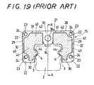
- FIGS. 17 to 19 in the accompanying drawings show a prior linear motion guide unit disclosed in, for example, Japanese Patent Laid-Open No. 93952/1999.
- the prior linear motion guide unit is primarily comprised of a track rail 2 and a carriage or slider 1 riding the track rail 2 astride for sliding movement.
- the track rail 2 is formed in a substantially rectangular shape in cross section, which are recessed on lengthwise side surfaces 3 thereof to provide raceway grooves 4.
- the slider 1 may move on the track rail 2 by virtue of rolling elements running through the raceway groove 4.
- the slider 1 includes a casing 5 recessed so as to fit over the track rail 2 for sliding movement with respect to the track rail 2, and end caps 6 mounted to forward and aft ends of the casing 5, one to each end.
- the casing 5 is made with raceway grooves 9 in opposition to the raceway grooves 4 on the track rail 2 to allow rolling elements 7 to run through between the confronting raceway grooves 4 and 9.
- Retainer bands 18 are provided in the casing 5 so as to embrace the rolling elements 7 to thereby prevent the rolling elements 7 from falling out of the casing 5.
- Bottom seals 8 are attached to the lower surfaces of the casing 5 and the end caps 6 to close clearances between the track rail 2 and the combined casing 5 and end caps 6.
- the rolling elements 7 run through load areas of raceways defined between the raceway grooves 4 on the track rail 2 and the raceway grooves 9 in the casing 5, then turnarounds formed in the end caps 6 and return passages 12 formed in parallel with the raceway grooves 9 in the casing 5.
- the rolling elements 7 are allowed to run through recirculating passages, each of which consists of the load area of the raceway defined between the confronting raceway grooves 4 and 9, and non-loaded area 22 composed of the turnarounds and return passages 12.
- the slider 1 is allowed to move in a sliding manner along the track rail 2 by virtue of the rolling elements 7 that roll through the load areas between the confronting raceway grooves 4 and 9.
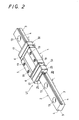
- Lubricating means 15 are fastened to end faces 16 of the forward and aft end caps 6, one to each end cap, so as to ride the track rail 2 astride.
- the lubricating means 15 are each comprised of a lubricant-impregnated plate 40 coming in sliding contact with the track rail 2, and a backing cartridge 21 to support the lubricant-impregnated plate 40 therein.
- Each lubricating means 15 is made in a platy configuration of uniform thickness and recessed in conformity with the cross section of the casing 5 so as to fit over and conform to the track rail 2 for sliding movement.
- the backing cartridge 21 has the contour substantially resembling a gate as a whole, which is composed of a ceiling section 28, a pair of side sections 29, 29 extending downward from the sidewise opposing ends of the ceiling section 28, and lower sections 30, 30 extending towards each other from the bottom ends of the side sections 29, 29.
- Each lubricating means 15 may fit over the track rail 2 with its ceiling section 28 lying in parallel with a top surface 14 of the track rail 2, the side sections 29, 29 depending downwards in parallel with the lengthwise side surfaces 3 of the track rail 2, and its lower sections 30, 30 extending towards the lengthwise side surfaces 3 of the track rail 2.
- the backing cartridge 21 holds in place the lubricant-impregnated plate 40 by surrounding around the periphery of the lubricant-impregnated plate 40, except areas facing the track rail 2.
- the lubricant-impregnated plate 40 is uncovered at its fore-and-aft major surfaces: forward and aft end surfaces facing against the end caps 6 and end seals 17 respectively.
- the lubricant-impregnated plate 40 is left exposed at its major end surfaces until covered with its associated end cap 6 and end seal 17 on the slider 1.
- the backing cartridge 21 conceals the periphery of the lubricant-impregnated plate 40 to seal pores in the porous structure, protecting the lubricant-impregnated plate 40 against contamination, breakage and escape of lubricant.
- the backing cartridge 21 although may be made of any one of metals, synthetic resins, synthetic rubbers and so on, is invariably made of any substance that may be much subject to either elastic deformation or plastic deformation restorable later in order to provide an easy to replace or handle the lubricating means 15.
- the lubricant-impregnated plate 40 is fitted in the backing cartridge 21, or only the lubricating means 15 is either mounted to or dismounted from the track rail 2 with all the casing 5, end caps 6 and end seals 17 left on the track rail 25, the backing cartridge 21 that may be easily subject to either plastic or elastic deformation without occurring breakage makes it possible to simply fit the lubricant-impregnated plate 40 into the backing cartridge 21 or mount the lubricating means 15 on the track rail 2.
- the lubricating means 15 will be attached to the casing 5 with the backing cartridge 21 being urged against the end faces of the end caps 6 fastened on the forward and aft ends of the casing 5, thence the backing cartridge 21 is reinforced at its four corners 22 where holes 24 are made for fastening bolts 25.
- the end caps 6 and end seals 17 sandwiching the backing cartridge 21 between them are also made with matching holes 26, 27 for the fastening bolts in alignment with the. holes 24 in the backing cartridge 21.
- the backing cartridge 21, together with the associated end cap 6 and end seal 17 keeping the backing cartridge 21 between them, is held on the slider 1 with the fastening bolts 25, which are stretched through the holes 26, 24 and 27 in the end cap 6, backing cartridge 21 and end seal 17, and ultimately screwed into holes in the casing 5 of the slider 1.
- the backing cartridge 21 made of synthetic resin or synthetic rubber
- collars 23 fit in holes 24 in such a manner that the collars 23 mostly sustain the squeezing force applied by the fastening bolts 25, which are inserted through the collars 23 and tightened, to thereby protect the backing cartridge 21 against the deformation or distortion that might otherwise happen due to the compressive force when tightened.
- the lubricant-impregnated plate 40 is divided into lubricant-impregnated halves 41, 41, which are arranged on opposite sides of the track rail 2 so as to separately come in sliding contact with their associated raceway grooves 4 on the track rail 2.
- the lubricant-impregnated halves 41, 41, assembled in the backing cartridge 21, are arranged spaced apart from one another with a middle area 33 in the backing cartridge 21.
- the lubricant-impregnated halves 41, 41 are separately accommodated in the backing cartridge 21, which is then fastened to the casing 5 in such a relation that the halves 41, 41 are arranged confronting the track rail 2.
- the backing cartridge 21 surrounding the lubricant-impregnated halves 41, 41 helps hold steadily them in place. Moreover, the backing cartridge 21 as stated earlier serves to cover the lubricant-impregnated halves 41, 41 against contamination and breakage as well as prevent the escape of lubricant.
- Each of the lubricant-impregnated halves 41, 41 is allowed to provide only as much volume as needed to lubricate the raceway grooves 4 and, therefore, the lubricant-impregnated plate 40 may be made more compact in size.
- the lubricant-impregnated halves 41, 41 are arranged in symmetry on the opposite sides of the track rail 2. Accommodating the lubricant-impregnated plate 40 in the backing cartridge 21, therefore, may be completed by putting merely mass-produced lubricant-impregnated halves 41, 41 of the same pattern in the backing cartridge 21 in such a fashion as to invert any one to the other with respect to the line A-A in FIG. 19. This makes it possible to use any mould of the same pattern to produce the lubricant-impregnated halves 41, 41, resulting in the reduction in manufacturing cost of the lubricating means 45.
- the backing cartridge 21 is made at the ceiling section 28 thereof with a middle area 33 extending towards a top surface 14 of the track rail 2.
- the lubricant-impregnated halves 41, 41, accommodated in the backing cartridge 21 are held in such a relation that they are isolated from each other and confined by the upper section 28 with the middle area 33, side sections 29, 29 and lower sections 30, 30. That is to say, the lubricant-impregnated halves 41, 41 are exposed to their confronting raceway grooves 4 on the track rail 2 at only the areas where none of the sections stated earlier exists.
- Windows 31, 32 are provided at the upper section 28 and the side sections 29, 29 of the lubricating means 15 to offer much saving in material for producing the backing cartridge 21 and also to make easy of the access to the lubricant-impregnated plate 40.
- the windows 31, 32 allow monitoring visually the lubricant-impregnated plate 40.
- the lubricant-impregnated plate 40 short of lubricant may be supplied with the lubricant through the windows 31, 32.
- the lubricant-impregnated halves 41, 41 have raised surfaces 42, 43, each of which has a height about half the depth of the associated window 31, 32 so as to make positive engagement with the windows 31, 32.
- Engaging the raised surfaces 42, 43 with the windows 31, 32 may be carried out with the elastic deformation of either both or any one of the lubricant-impregnated halves 41, 41 and backing cartridge 21, for example, by sidewise stretching somewhat the backing cartridge 21 or compressing the lubricant-impregnated halves 41, 41.
- Engagement of the raised surfaces 42, 43 in the windows 31, 32 assures reliable fit of the lubricant-impregnated halves 41, 41 inside the backing cartridge 21, helping keep the lubricant-impregnated halves 41, 41 against falling off from the backing cartridge 21, which might otherwise happen before attaching on the slider 1 or after detaching from the slider 1.
- the lubricant-impregnated plate 40 is composed of a sintered resinous component of porous structure including continuous voids therein, which are impregnated with lubricating oil.
- the sintered resinous component for the lubricant-impregnated plate 40 is fabricated by pressing fine powder of synthetic resins in a mould under high temperature.
- the lubricant-impregnated plate 40 is provided on the inside periphery thereof with convexities 44, which are raised inwardly so as to come in sliding contact with the raceway grooves 4 on the track rail 2 to continually supply the lubricant or lubricating oil from the lubricant-impregnated plate to the raceway grooves 4.
- Molded product for the lubricant-impregnated plate 40 is any sintered resinous porous component with open cells, which may be produced by filling a preselected mould with the powdery ultrahigh molecular weight polyethylene resin better in bonding with metals and having the grading of, for example, either fine grain size of 30 ⁇ m or coarse grain size of from 250 ⁇ m to 300 ⁇ m, and then heating the molded resin under high pressure.
- the sintered resinous component produced as described above for the lubricant-impregnated plate 40 has the porous structure of the porosity of, for example, from 40% to 50%.
- the lubricant-impregnated plate 40 is prepared by immersing the sintered porous resinous component with lubricant of turbine oil to fill the voids with the lubricant. Dipping the sintered resinous component into, for example, turbine oil for about 30 minutes may provides the lubricant-impregnated plate 40 that is regulated at percentage of lubricating oil content of 41% by weight and thus at oil content of about 2cc. Percentage of lubricating oil content may be controlled in accordance with the operating condition of the slider 1.
- the sintered resinous component for the lubricant-impregnated plate 40 may be easily formed with high accuracy of finishing within, for example, about ⁇ 0.025mm. This makes it possible to provide the component that is most suitable for the linear motion guide units incorporated into the precision machines.
- lubrication of the raceway grooves on the track rail may be effected with the lubricant that is applied from the lubricant-impregnated plate with no external force pressing the plate against the raceway grooves.
- This makes it possible to reduce frictional resistance that might otherwise much causes from the sliding movement of the lubricant-impregnated plate relative to the raceway grooves, whereby the lubricant-impregnated plate may be less subject to wear owing to relative sliding movement between the lubricant-impregnated plate and the track rail.
- a pair of lubricant-impregnated halves for the lubricant-impregnated plate fits in the backing cartridge by making engagement with the windows at their upper and side peripheral areas. Nevertheless, the end face formed integrally with the backing cartridge, even when abutted against any one of forward and aft surfaces of the lubricant-impregnated halves, supports the lubricant-impregnated halves at their but any one side of the forward and aft surfaces. In current art, therefore, the lubricant-impregnated halves sometimes are not supported successfully.
- the present invention has for its primary aim to overcome the problems as described just above, especially provide a linear motion guide unit in which lubricating means is disposed between an end cap and an end seal, the lubricating means being comprised of a cartridge, a lubricant-impregnated plate accommodated in the cartridge, and a backing plate reinforcing the lubricant-impregnated plate, whereby the lubricating means reduces frictional resistance encountered when a slider moves over a track rail, helping ensure smooth reciprocating movement of the slider relatively of the track rail, and much decreasing deformation, wear and clogging, and so on in the lubricant-impregnated plate.
- the present invention is concerned with a linear motion guide unit comprising; a track rail provided lengthwise with first raceway grooves and a slider movable with respect to the track rail; the slider being composed of a casing made with second raceway grooves confronting the first raceway grooves and return passages, rolling elements running through load areas formed between the confronting first and second raceway grooves, end caps fastened to end faces of the casing, one to each end face, and provided therein with turnarounds connecting the load areas and the return passages to form recirculating passages where the rolling elements are allowed to run through in an endless manner, lubricating means arranged on end faces of the end caps, one to each end cap, to lubricate the first raceway grooves formed on the track rail, and end seals disposed over the lubricating means; wherein the lubricating means is comprised of a lubricant-impregnated plate made of a sintered resinous component of porous structure impregnated with lubricant, a backing plate attached to any one of oppos
- a linear motion guide unit wherein a lubricant-impregnated plate is reinforced or supported with a backing plate attached to the lubricant-impregnated plate to form a composite plate, which is then assembled with a cartridge in such a manner that the lubricant-impregnated plate in the cartridge is lidded with the backing plate.
- the lubricant-impregnated plate is held or supported on both the opposite sides thereof with the backing plate and the cartridge, respectively, thus kept against deformation or distortion that might otherwise happen due to any external force.
- the lubricant-impregnated plate is not urged excessively against the raceway grooves on the track rail, nor are they spaced apart largely away from the raceway grooves. This makes it possible to continue keeping the lubricant-impregnated plate in substantial contact relation with the raceway grooves to incessantly apply a desired amount of lubricant to the raceway grooves.
- the sliding movement of the lubricant-impregnated plate over the track rail is made even smoother and more stable, so that the frictional resistance that occurs between the lubricant-impregnated plate and the associated raceway groove decreases and, thus, the lubricant-impregnated plate is less subject to wear, which might be owing to the sliding movement.
- a linear motion guide unit wherein the lubricant-impregnated plate includes a major portion contained in the cartridge to store the lubricant therein, and a minor portion formed integrally with the major portion and allowed to come in sliding contact with any associated raceway groove formed on the track rail to apply the lubricant stored in the major portion onto the associated raceway groove.
- the cartridge is provided therein with a window to allow the minor portion to protrude out of the cartridge.
- the lubricant-impregnated plate although enclosed with the cartridge to be held certainly in precise geometry, has a portion raised from the major potion thereof, which protrude outwardly through the window formed in the cartridge, coming in sliding contact with the raceway grooves on the track rail.
- a linear motion guide unit wherein the lubricating means is disposed between the end seal and the end cap, and fastened to the casing together with the end seal and end cap by means of bolts, and wherein fastening stress caused when the bolt is fastened down is sustained by both the backing plate and the cartridge so that the lubricant-impregnated plate is free of the fastening stress.
- the fastening load due to bolts to clamp together the lubricating means and end seals is sustained directly by only both the backing plate and the cartridge and, therefore, the lubricant-impregnated plate is kept against the deformation or distortion that might otherwise happen owing to the fastening load caused by the bolt.
- a linear motion guide unit wherein the cartridge is provided with a collar in which the bolt fits for fastening, and wherein the collar comes in abutment against the backing plate at an area where the bolt extends for fastening, thereby transmit the fastening stress to the backing plate.
- a linear motion guide unit wherein the backing plate is provided with a piercing claw, and wherein the lubricant-impregnated plate is mounted to the backing plate by piercing the lubricant-impregnated plate with the claw.
- a linear motion guide unit wherein the lubricant-impregnated plate is divided into a pair of lubricant-impregnated halves with respect to the track rail.
- the sintered resinous component for the lubricant-impregnated plate is produced by heating finely powdered synthetic resin of ultrahigh molecular weight polymers under pressure in a design mould.
- a linear motion guide unit wherein the track rail has the raceway grooves on lengthwise-extending, widthwise-opposing side surfaces thereof, and wherein the slider rides the track rail astride for sliding movement relatively to the track rail.
- the track rail is formed in an U-shape in cross-section, which includes widthwise opposing side-walls provided on lengthwise inward surfaces thereof with the first raceway grooves, and wherein the slider fits between the widthwise opposing side-walls for sliding movement with respect to the track rail.
- the sintered resinous component is simply machined to tolerance of about ⁇ 0.025 and the lubricant-impregnated plate is mounted with the backing plate at any one of the opposite major surfaces thereof while mounted with the cartridge at another major surface.
- the lubricant-impregnated plate is certainly held in place with less possibility of deformation and distortion by virtue of the backing plate and the cartridge. That is to say, the backing plate and the cartridge, in combination, effectively keep the lubricant-impregnated plate against deformation and distortion to continue keeping the high accuracy of a clearance between the confronting lubricant-impregnated plate and the raceway groove.
- the frictional resistance occurring between the slider and the track rail may be significantly reduced so that the slider is allowed to traverse smoothly along the track rail.
- the lubricant-impregnated plate applies continually lubricant to the raceway grooves, which are thus kept in well lubrication, while the problem of wear is eliminated whereby the lubricant-impregnated plate is kept from getting clogged at areas coming in contact with the raceway grooves.
- the lubricating means of the present invention may be simply mounted on the forward and aft ends of the slider of the current linear motion guide unit incorporated in the machine bed and so on.
- the present invention contributes to improvement on the self-lubrication performance of the obsolete linear motion guide units.
- FIGS. 1 to 16 showing the preferred embodiments of the present invention
- like parts and components compared with the prior linear motion guide unit in FIGS. 17 to 19 are given the same characters, so that the previous description will be applicable.
- the linear motion guide unit U1 is suitable for small-sized machines operating under relatively small load.
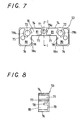
- the linear motion guide unit U1 is mainly comprised of an elongated track rail 2 of substantially rectangular shape in cross section having lengthwiseextended raceway grooves 4, one on each side surface 3 of the track rail 2, and a slider 1 mounted astride the track rail 2 for sliding movement.
- the slider 1 includes a casing 5 made with raceway grooves confronting the raceway grooves 4, end caps 6 attached to forward and aft end faces of the casing 5, respectively, lubricating means 50 disposed in contact with end faces of the end caps 6, and end seals 17 arranged over end faces of the lubricating means 50.
- the lubricating means 50 as seen from FIG. 1, is sandwiched between the associated end cap 6 and end seal 17, clamped together with fastening bolts 25.
- the lubricating means 50 is composed of a pair of lubricant-impregnated halves 51, 51 disposed on widthwise opposite sides of the track rail 2, one to each side, a backing plate 52 arranged on a major surface of the lubricant-impregnated halves, which confronts the associated end cap 6, and a cartridge 53 for accommodating therein the lubricant-impregnated halves 51, 51.
- the lubricating means 50 is an assembled lubricator uniform in fore-and-aft thickness, which is formed in a recessed configuration conforming with the configured end of the casing 5 so as to ride the track rail 2 astride for sliding movement.
- the lubricant-impregnated plate 51 as seen from FIG. 1, is divided into lubricant-impregnated halves 51a, 51b, which may separately come in sliding contact with the raceway grooves 4 on the lengthwise side surfaces 3 of the track rail 2.
- Each of the lubricant-impregnated halves 51a, 51b is allowed to provide only as much volume as needed to lubricate the raceway grooves 4 and, therefore, the lubricant-impregnated plate 51 may be made more compact in size.
- the lubricant-impregnated halves 51a, 51b will be simply secured to the backing plate 52 into a composite plate by putting merely mass-produced lubricant-impregnated halves 51a, 51b of the same pattern in such a fashion as to invert any one to the other. Then, the composite plate is accommodated in the cartridge 53. Moreover, the backing plate 52 and the cartridge 53 are formed in symmetry on widthwise opposite sides with respect to their common center. These make it possible to use any mould of the same pattern to produce the lubricant-impregnated halves 51a, 51b, resulting in the reduction in manufacturing cost of the lubricating means 50.
- the lubricant-impregnated half 51a has major portions 54, 55 connected with one another through a narrow bridge 56, and a protrusion 57 extending upwards from the major portion 54.
- the major portion 54, bridge portion 56 and protrusion 57 in combination, define a cove 58 in which a bolt 25 fits to fasten the lubricating means 50.
- the major portion 54 is also made with a raised portion 59 having a convex surface, which comes in sliding contact with the associated raceway groove 4 on the track rail 2 to apply lubricant over the raceway groove 4. Lubricant contained in the major portions 54, 55 is applied to the associated raceway groove 4 through the raised portion 59.
- the lubricant-impregnated halves 51a, 51b are made of sintered resinous component of porous structure, which is produced by heating finely powdered synthetic resin of ultrahigh molecular weight polymers and so on under pressure in a mould of preselected design. Open voids of cells in porous structure of the sintered resinous component are filled with oily lubricant.
- the lubricant-impregnated plate 51 may be formed to a tolerance as strict as possible of substantially zero with respect to the raceway grooves 4 on the track rail 2.
- the lubricant-impregnated plate 51 may be made to provide a negative allowance of interference, by which the lubricant-impregnated plate 51 is allowed to fit under a somewhat pre-stressed condition.
- the lubricant-impregnated halves 51a, 51b are kept in contact with the raceway grooves 4 on the track rail 2, to continually apply the lubricant, which are held in the lubricant-impregnated halves 51a, 51b, over the raceway grooves 4.
- Resinous component produced by firing powdery ultrahigh molecular weight polyethylene resin in a mould moreover, has an intrinsic mechanical property that it is less subject to wear even after repeated sliding motions.
- the lubricant-impregnated halves 51a, 51b are kept from getting clogged with debris or cuttings.
- the lubricant-impregnated halves 51a, 51b short of lubricant after consumption of the lubricant may be replenished with fresh lubricant. This ensures the long-lasting service life of the lubricating means 50.
- the backing plate 52 in the lubricating means 50 is made of a single metallic plate 60 mounted spanning both the lubricant-impregnated halves 51a, 51b.
- the metallic plate 60 is made at the center thereof with an opening 61 serving to connect the slider 1 to lubricant-supply means such as a grease nipple, and further is provided with a pair of bolt holes 62, 62 widthwise opposing with respect to the central opening 61.
- the lubricating means 50 is fastened to the slider 1 with bolts 25, 25 extending through the holes 62, 62.
- the metallic plate 60 moreover, has pointed projections or hooks at areas confronting the major portions 54, 55 of the lubricant-impregnated halves 51a, 51b.
- the pointed projections or hooks are bent to such a specific angle as to provide claws 64, 65 that are easily piercable into the sintered resinous component to adhere the backing plate 52 to the lubricant-impregnated halves 51a, 51b.
- backing plate 52 may be effectively fastened to the lubricant-impregnated halves 51a, 51b by simply piercing them with the claws 64, 65, either before or after the lubricant is impregnated into the sintered resinous components.
- the backing plate 52 may well keep the lubricant-impregnated halves 51a, 51b against deformation even under the working condition where the lubricant-impregnated halves 51a, 51b experience the external force that might otherwise causes such deformation.
- the backing plate 52 helps ensure the precise geometry and configuration of the surface areas of the lubricant-impregnated halves 51a, 51b, which come in sliding contact with the raceway grooves 4.
- the lubricant-impregnated halves 51a, 51b are not urged excessively against the raceway grooves 4, nor are they spaced apart largely away from the raceway grooves 4. This makes it possible to incessantly apply the sufficient lubricant to the raceway grooves 4 with no increase of the sliding resistance to the raceway grooves 4.
- the lubricant-impregnated halves 51a, 51b are contained in the cartridge 53, which is made of any one of metals, synthetic resins, synthetic rubbers, and so on, and formed with widthwise opposing sleeves so as to ride the track rail 2 astride, as with the casing 5 of the slider 1.
- the cartridge 53 has a major front wall 70 to shield over front faces of the lubricant-impregnated halves 51a, 51b.
- the major front wall 70 is bored with a central opening 71 and widthwise opposing holes 72, which are, respectively, located in alignment with the central opening 61 and the widthwise holes 62 in the backing plate 52.
- the cartridge 53 includes a ceiling wall 74, widthwise opposing side walls 75, 75 and floor walls 76, 76, which are integral with the major front wall 70 and continuous with one another to provide a peripheral wall to cover allover uppers, sides and bottoms of the lubricant-impregnated halves 51a, 51b.
- the cartridge 53 is further provided with inward wall sections made integrally with the major front wall 70, which consist of inward floor walls 77, 77 extending to hold in place thereon the major portions 55 of the lubricant-impregnated halves 51a, 51b, and retainer portions 78, 78 spacing away above the floor walls 76, 76 and extending from the major front wall 70 up to a height midway the fore-and-aft thickness of the cartridge.
- Windows 78a, 78a are left between the floor walls 76, 76 and the retainer portions 78, 78, through which the raised portions 59 of the lubricant-impregnated halves 51a, 51b are allowed to project outwardly to the track rail 2.
- the cartridge 53 also has cylindrical collars 79a, 79b that are formed integrally with the major front wall 70 in alignment with the central opening 71 and the widthwise opposing holes 72, respectively.
- the collars 79a, 79b when tightened together with the grease nipple and fastening bolts inserted there, come in abutment against the backing plate 52 to let the backing plate 52 assume entirely squeezing or clamping stress.
- the major portions 54, 55 of the lubricant-impregnated halves 51a, 51b are spaced apart from each other and accommodated in compartments 80, 81 each defined by the associated peripheral wall, inward wall section and collars, while the raised portions 59 of the lubricant-impregnated halves 51a, 51b protrude out of the windows 78a to come to make sliding contact with the raceway grooves 4.
- the lubricant-impregnated halves 51a, 51b are set individually on the track rail 2 into the complete lubricant-impregnated plate 51, to which the backing plate 52 is then secured to provide the composite plate. Further the cartridge 53 encloses therein the composite plate thereby finishing the lubricating means 50, which is finally fastened to the casing 5 to keep precise geometry with respect to the track rail 2.
- the cartridge 53 as surrounding around the lubricant-impregnated plate 51, serves not only to help keep the lubricant-impregnated plate 51 in place with stability, but also to preserve the lubricant-impregnated plate 51 from contamination by cuttings, dust and dirt, breakage and escape of lubricant.
- the cartridge 53 is formed in a single part receiving therein both the lubricant-impregnated halves 51a, 51b. This construction results in making handling of the lubricant-impregnated plate 51 much easier.
- FIGS. 9 to 16 there is shown another embodiment of the linear motion guide unit of the present invention.
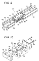
- the linear motion guide unit U2 in FIGS. 9 to 16 as opposed to the linear motion guide unit U1 shown earlier in FIGS. 1 to 8, is the type well available for the large-sized machine sustainable heavy load, and has an elongated track rail 102 formed in an U-shape in cross-section, which includes widthwise opposing side-walls 120 made on lengthwise inward surfaces 103 thereof with raceway grooves 104.
- this embodiment is substantially identical in basic construction of the sliding mechanism with the first embodiment explained earlier, with the exception of the modified lubricating means 150.
- the track rail 102 has inwardly a guide channel 110 in which a slider 101 fits for lengthwise sliding movement.
- the track rail 102 is secured to any machine bed with fasten-down bolts that fit in holes 113.
- the slider 101 has a casing 105 mounted on forward and aft ends thereof with end caps 106, one to each end, which are further mounted thereon with end seals 117.
- a lubricant-impregnated plate 105 is divided equally into two pieces of lubricant-impregnated halves 151a, 151b, each of which is arranged individually so as to make sliding contact with any associated raceway groove 104 on the lengthwise inward surface 103 of the track rail 102.
- a composite plate in this embodiment is also prepared by fixing merely mass-produced lubricant-impregnated halves 151a, 151b of the same pattern on a backing plate 152 in such a fashion as to invert any one to the other.
- the composite plate is assembled together with a cartridge 153 into the lubricating means 150 in such a manner that the lubricant-impregnated plate 151 is contained in the cartridge 153 lidded with the backing plate 152.
- both the backing plate 152 and the cartridge 153 are formed in symmetry with respect to their common widthwise centerline.
- the lubricant-impregnated half 151a has a major portion 154 that is made at the upper area thereof with an upward opened recess 158 for a fastening bolt 125.
- the major portion 154 is also made with a raised portion 159 having a convex surface, which comes in sliding contact with the associated raceway groove 104 of the track rail 102 to apply lubricant over the raceway groove 104. Lubricant contained in the major portion 154 is applied to the associated raceway groove 104 through the raised portion 159.
- Materials and production process of sintered resinous component for the lubricant-impregnated halves 151a, 151b are the same as that of the lubricant-impregnated halves 51a, 51b described earlier.
- Mechanical functions of the lubricant-impregnated plate 151; sliding engagement of the lubricant-impregnated plate 151 with the raceway grooves 104 on the track rail 102, lubricant supply to the raceway grooves 104, protection against getting clogged by cuttings, and so on are the same as described earlier for the lubricant-impregnated plate 51 in the first embodiment.
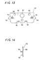
- FIGS. 13 and 14 illustrate the backing plate 152 for the lubricating means 150, which is made of a sheet of metallic plate 160 spanning both the lubricant-impregnated halves 151a, 151b.
- the metallic plate 160 is made at the center thereof with an opening 61 serving to connect the slider 101 to lubricant-supply means such as a grease nipple, and further is provided with three bolt holes 162 arranged spaced apart widthwise from each other, where fastening bolts 162 fit in to connect the lubricating means 150 to the slider 101.
- the backing plate 152 is made at widthwise opposing edges with convex portions 163, which are configured so as to conform to the raised portions 159 of the lubricant-impregnated halves 151a, 151b, thereby supporting or reinforcing the raised portions 159.
- the metallic plate 160 has pointed projections or hooks at areas confronting the major portions 154, 154 of the lubricant-impregnated halves 151a, 151b.
- the pointed projections or hooks are bent to such a specific angle as to provide claws 164, 165 that are easily piercable into the sintered resinous component to adhere the backing plate 152 to the lubricant-impregnated halves 151a, 151b.
- backing plate 152 may be effectively fastened to the lubricant-impregnated halves 151a, 151b by simply piercing them with the claws 164, 165.
- the backing plate 152 well helps protect the lubricant-impregnated halves 151a, 151b against deformation or distortion at their raised portions 159, keeping precise sliding relation of the raised portions 159 with the raceway grooves 104, thus reducing the friction encountered when the raised portions 159 slide along the raceway grooves 104.
- the lubricating means 150 also ensures well lubrication of the raceway grooves 104.
- the lubricant-impregnated plate 151 is contained in a cartridge 153 shown in FIGS. 15 and 16, which is made of any one of metals, synthetic resins, synthetic rubbers and so on and formed in a configuration that is accommodated, as with the casing 105 of the slider 101, in the guide channel 110 of U-shape in the track rail 2.
- the cartridge 153 has a major front wall 170 to shield over front faces of the lubricant-impregnated halves 151a, 151b.
- the major front wall 170 is bored with a central opening 171 for the grease nipple and other three holes 172 for the fastening bolts 125, which are, respectively, located in alignment with the central opening 161 and the holes 162 in the backing plate 152.
- the cartridge 153 has a peripheral wall integral with the major front wall 170 to cover uppers, sides and bottoms of the lubricant-impregnated halves 151a, 151b.
- the peripheral wall is composed of a ceiling wall 174, widthwise opposing side walls 175a turning downward at the widthwise opposing ends of the ceiling wall 174, a floor wall 176 and other side walls 175b turning upward at the widthwise opposing ends of the floor wall 176.
- the cartridge 153 has an inside partition 178 integral with the major front wall 170 while surrounding around the central opening 171, thereby defining in place the widthwise inward edges of the major portions 154, 154 of the lubricant-impregnated halves 151a, 151b when accommodated in the cartridge 153.
- the inside partition 178 consists of a larger collar 179a around the central opening 171 for the grease nipple and a lesser collar 179b around the central hole 172 for the fastening bolt. Left between the confronting side walls 175a and 175b are windows 176 where the raised portions 159 of the lubricant-impregnated halves 151a, 151b is allowed to protrude outwardly.
- the cartridge 153 is provided therein with other collars 179b formed integrally with the major front wall 170 to surround around other bolt holes 172, 172 spaced apart widthwise from each other.
- the collars 179a, 179b when tightened together with the grease nipple and fastening bolts inserted there, come in abutment against the backing plate 152 to let the backing plate 152 assume entirely squeezing or clamping stress.
- the major portions 154 of the lubricant-impregnated halves 151a, 151b are spaced apart from each other and accommodated in compartments 180, 181 each defined by the associated peripheral wall, inside partition and collars 179a, 179b, while the raised portions 159 of the lubricant-impregnated halves 151a, 151b protrude out of the windows 176 to come to make sliding contact with the raceway grooves 104.
- the fastening bolts 125 after having passed through the end seal 117, the holes 172 in the cartridge 153, the recess 158 in the lubricant-impregnated plate 151 and the bolt holes 162 in the backing plate 152, from one to another, are ultimately screwed into the threaded holes in the casing 105.
- the squeezing force due to the fastening bolts 125 since transmitted to both the backing plate 152 and the end cap 106 through, especially, the collars 179b in the cartridge 153, exerts no substantial action on the lubricant-impregnated halves 151a, 151b.
- the lubricating means 150 in the second embodiment is substantially identical in its assembly and mounting to the casing 105 with the lubricating means 50 stated earlier. Functions realized by the cartridge 53 in the first embodiment stated earlier; precise mounting, protection against getting contaminated by debris, prevention against breakage and escape of lubricant, and easy handling of the lubricant-impregnated plate 151 are equally applicable to the cartridge 153 in the second embodiment.
- the sintered resinous component for the lubricant-impregnated plate 51, 151 described above may be designed such that, for example, the raised portions 59, 159 coming in sliding contact with the raceway grooves 4, 104 of the track rail 2, 102 are made rich in porosity, whereas the residual portions are made less in porosity.
- the portions rich in porosity are highly susceptible of absorbing lubricating oil to admit the positive flow of lubricating oil into the highly porous portions themselves.
- the sintered resinous component having two parts different in porosity from each other may be fabricated, for example, by using any kind of powdery resinous materials differing in grain size, or by regulating the sintering temperature.
- the lubricant-impregnated plate 51, 151 may be made of a unitary plate in return for the divided two halves arranged in opposite sides of the track rail 2, 102.
Landscapes
- Engineering & Computer Science (AREA)
- General Engineering & Computer Science (AREA)
- Mechanical Engineering (AREA)
- Bearings For Parts Moving Linearly (AREA)
- Rolling Contact Bearings (AREA)
Applications Claiming Priority (2)
| Application Number | Priority Date | Filing Date | Title |
|---|---|---|---|
| JP37304399 | 1999-12-28 | ||
| JP37304399A JP4268298B2 (ja) | 1999-12-28 | 1999-12-28 | 直動案内ユニット |
Publications (2)
| Publication Number | Publication Date |
|---|---|
| EP1114941A1 true EP1114941A1 (de) | 2001-07-11 |
| EP1114941B1 EP1114941B1 (de) | 2005-06-08 |
Family
ID=18501482
Family Applications (1)
| Application Number | Title | Priority Date | Filing Date |
|---|---|---|---|
| EP00310859A Expired - Lifetime EP1114941B1 (de) | 1999-12-28 | 2000-12-06 | Linearführungseinheit |
Country Status (4)
| Country | Link |
|---|---|
| US (1) | US6517244B2 (de) |
| EP (1) | EP1114941B1 (de) |
| JP (1) | JP4268298B2 (de) |
| DE (1) | DE60020666T2 (de) |
Cited By (1)
| Publication number | Priority date | Publication date | Assignee | Title |
|---|---|---|---|---|
| US20170097041A1 (en) * | 2015-10-02 | 2017-04-06 | Ome Technology Co., Ltd. | Linear guideway, circulating module thereof, and slider thereof |
Families Citing this family (11)
| Publication number | Priority date | Publication date | Assignee | Title |
|---|---|---|---|---|
| JP4384379B2 (ja) * | 2001-09-20 | 2009-12-16 | 日本トムソン株式会社 | 方向転換路とリターン路とを接続管部で連通した直動案内ユニット |
| CN1314905C (zh) * | 2003-04-11 | 2007-05-09 | 日本精工株式会社 | 线性导轨装置 |
| DE102005037046B4 (de) * | 2004-08-05 | 2017-03-30 | Nsk Ltd. | Linearführungs-Lagervorrichtung |
| JP4615466B2 (ja) * | 2006-03-22 | 2011-01-19 | 日本トムソン株式会社 | 高密封シール装置を備えた直動案内ユニット |
| JP5321051B2 (ja) * | 2008-12-26 | 2013-10-23 | 日本精工株式会社 | 直動案内装置 |
| DE202009009548U1 (de) * | 2009-07-10 | 2009-09-10 | Dorma Gmbh + Co. Kg | Deckenschienensystem zur Führung von Wandelementen |
| JP5965369B2 (ja) * | 2013-09-05 | 2016-08-03 | Thk株式会社 | 運動案内装置 |
| TWM519693U (zh) * | 2015-10-02 | 2016-04-01 | Ome Technology Co Ltd | 線性滑軌及其自潤模組 |
| DE102020202872B4 (de) * | 2020-03-06 | 2022-02-03 | Festo Se & Co. Kg | Linearführungseinrichtung |
| JP2022093941A (ja) * | 2020-12-14 | 2022-06-24 | 日本トムソン株式会社 | 直動案内ユニット |
| JP7416006B2 (ja) * | 2021-04-02 | 2024-01-17 | Smc株式会社 | リニアガイド |
Citations (7)
| Publication number | Priority date | Publication date | Assignee | Title |
|---|---|---|---|---|
| US5492413A (en) * | 1993-07-22 | 1996-02-20 | Nsk Ltd. | Sealing device for a linear guide |
| JPH09126235A (ja) * | 1995-10-31 | 1997-05-13 | Nippon Seiko Kk | 潤滑剤溜り装置付直動案内軸受装置 |
| EP0874172A1 (de) * | 1996-11-11 | 1998-10-28 | Thk Co., Ltd. | Linearführungsvorrichtung und schmierölzufuhrsystem dafür |
| EP0902201A2 (de) * | 1997-09-09 | 1999-03-17 | Nippon Thompson Co., Ltd. | Linearführungseinheit |
| EP0905395A1 (de) * | 1997-09-18 | 1999-03-31 | Nippon Thompson Co., Ltd. | Führungseinheit für Linearbewegungen |
| US5967667A (en) * | 1997-01-17 | 1999-10-19 | Nippon Thompson Co., Ltd. | Lubricating plate-carrying linear motion guide unit |
| JPH11351251A (ja) * | 1998-06-05 | 1999-12-24 | Nippon Thompson Co Ltd | 潤滑プレートを備えた直動案内ユニット |
Family Cites Families (5)
| Publication number | Priority date | Publication date | Assignee | Title |
|---|---|---|---|---|
| JPH0447447Y2 (de) * | 1987-01-19 | 1992-11-10 | ||
| JP3288961B2 (ja) * | 1996-11-11 | 2002-06-04 | テイエチケー株式会社 | 直線運動装置及びこれに使用される潤滑油供給装置 |
| JP3508503B2 (ja) * | 1997-10-02 | 2004-03-22 | 日本精工株式会社 | リニアガイド装置 |
| JP4086960B2 (ja) * | 1998-04-10 | 2008-05-14 | Thk株式会社 | 直線運動装置の保護スクレーパ及び直線運動装置 |
| JP2001041305A (ja) * | 1999-07-30 | 2001-02-13 | Iai:Kk | アクチュエータ |
-
1999
- 1999-12-28 JP JP37304399A patent/JP4268298B2/ja not_active Expired - Lifetime
-
2000
- 2000-12-06 EP EP00310859A patent/EP1114941B1/de not_active Expired - Lifetime
- 2000-12-06 US US09/729,795 patent/US6517244B2/en not_active Expired - Lifetime
- 2000-12-06 DE DE60020666T patent/DE60020666T2/de not_active Expired - Lifetime
Patent Citations (7)
| Publication number | Priority date | Publication date | Assignee | Title |
|---|---|---|---|---|
| US5492413A (en) * | 1993-07-22 | 1996-02-20 | Nsk Ltd. | Sealing device for a linear guide |
| JPH09126235A (ja) * | 1995-10-31 | 1997-05-13 | Nippon Seiko Kk | 潤滑剤溜り装置付直動案内軸受装置 |
| EP0874172A1 (de) * | 1996-11-11 | 1998-10-28 | Thk Co., Ltd. | Linearführungsvorrichtung und schmierölzufuhrsystem dafür |
| US5967667A (en) * | 1997-01-17 | 1999-10-19 | Nippon Thompson Co., Ltd. | Lubricating plate-carrying linear motion guide unit |
| EP0902201A2 (de) * | 1997-09-09 | 1999-03-17 | Nippon Thompson Co., Ltd. | Linearführungseinheit |
| EP0905395A1 (de) * | 1997-09-18 | 1999-03-31 | Nippon Thompson Co., Ltd. | Führungseinheit für Linearbewegungen |
| JPH11351251A (ja) * | 1998-06-05 | 1999-12-24 | Nippon Thompson Co Ltd | 潤滑プレートを備えた直動案内ユニット |
Non-Patent Citations (2)
| Title |
|---|
| PATENT ABSTRACTS OF JAPAN vol. 1997, no. 09 30 September 1997 (1997-09-30) * |
| PATENT ABSTRACTS OF JAPAN vol. 2000, no. 03 30 March 2000 (2000-03-30) * |
Cited By (2)
| Publication number | Priority date | Publication date | Assignee | Title |
|---|---|---|---|---|
| US20170097041A1 (en) * | 2015-10-02 | 2017-04-06 | Ome Technology Co., Ltd. | Linear guideway, circulating module thereof, and slider thereof |
| US9677610B2 (en) * | 2015-10-02 | 2017-06-13 | Ome Technology Co., Ltd. | Linear guideway and end module thereof |
Also Published As
| Publication number | Publication date |
|---|---|
| US6517244B2 (en) | 2003-02-11 |
| DE60020666D1 (de) | 2005-07-14 |
| DE60020666T2 (de) | 2006-05-04 |
| US20020039458A1 (en) | 2002-04-04 |
| EP1114941B1 (de) | 2005-06-08 |
| JP4268298B2 (ja) | 2009-05-27 |
| JP2001187919A (ja) | 2001-07-10 |
Similar Documents
| Publication | Publication Date | Title |
|---|---|---|
| JP3935247B2 (ja) | 直動案内ユニット | |
| EP0902201B1 (de) | Linearführungseinheit | |
| JP3980778B2 (ja) | 直動案内ユニット | |
| US6257766B1 (en) | Linear motion guide unit with lubricating means | |
| EP1114941B1 (de) | Linearführungseinheit | |
| US6176617B1 (en) | Linear motion guide unit with lubricating plate assembly | |
| EP1760342B1 (de) | Linearführungseinheit | |
| EP1645763B1 (de) | Linearführungseinheit | |
| EP2613063B1 (de) | Führungsvorrichtung für linearbewegungen | |
| US6190046B1 (en) | Linear motion guide unit with lubricating plate assembly | |
| US7762722B2 (en) | Linear motion guide unit | |
| US5967667A (en) | Lubricating plate-carrying linear motion guide unit | |
| JP5820187B2 (ja) | 小形直動案内ユニット | |
| US7341378B2 (en) | Linear motion guide unit | |
| EP0972961B1 (de) | Linearführungseinheit mit einer Schmierungsscheibe | |
| US7997800B2 (en) | Linear motion guide unit with mounting plate | |
| CN212225910U (zh) | 一种用于线性模组的移动平台组件及线性模组 | |
| JP4106904B2 (ja) | 直動案内軸受装置のスライダー及び直動案内軸受装置 | |
| CN210034170U (zh) | 一种新型线性滑轨 | |
| JPH0942286A (ja) | 直動転がり案内ユニット | |
| CN114623157A (zh) | 直动引导单元 |
Legal Events
| Date | Code | Title | Description |
|---|---|---|---|
| PUAI | Public reference made under article 153(3) epc to a published international application that has entered the european phase |
Free format text: ORIGINAL CODE: 0009012 |
|
| AK | Designated contracting states |
Kind code of ref document: A1 Designated state(s): DE GB |
|
| AX | Request for extension of the european patent |
Free format text: AL;LT;LV;MK;RO;SI |
|
| 17P | Request for examination filed |
Effective date: 20010720 |
|
| AKX | Designation fees paid |
Free format text: DE GB |
|
| 17Q | First examination report despatched |
Effective date: 20040322 |
|
| GRAP | Despatch of communication of intention to grant a patent |
Free format text: ORIGINAL CODE: EPIDOSNIGR1 |
|
| RIC1 | Information provided on ipc code assigned before grant |
Ipc: 7F 16C 33/66 A Ipc: 7F 16C 33/10 B Ipc: 7F 16C 29/06 B |
|
| GRAS | Grant fee paid |
Free format text: ORIGINAL CODE: EPIDOSNIGR3 |
|
| GRAA | (expected) grant |
Free format text: ORIGINAL CODE: 0009210 |
|
| AK | Designated contracting states |
Kind code of ref document: B1 Designated state(s): DE GB |
|
| REG | Reference to a national code |
Ref country code: GB Ref legal event code: FG4D |
|
| REF | Corresponds to: |
Ref document number: 60020666 Country of ref document: DE Date of ref document: 20050714 Kind code of ref document: P |
|
| PLBE | No opposition filed within time limit |
Free format text: ORIGINAL CODE: 0009261 |
|
| STAA | Information on the status of an ep patent application or granted ep patent |
Free format text: STATUS: NO OPPOSITION FILED WITHIN TIME LIMIT |
|
| 26N | No opposition filed |
Effective date: 20060309 |
|
| PGFP | Annual fee paid to national office [announced via postgrant information from national office to epo] |
Ref country code: DE Payment date: 20191120 Year of fee payment: 20 |
|
| PGFP | Annual fee paid to national office [announced via postgrant information from national office to epo] |
Ref country code: GB Payment date: 20191114 Year of fee payment: 20 |
|
| REG | Reference to a national code |
Ref country code: DE Ref legal event code: R071 Ref document number: 60020666 Country of ref document: DE |
|
| REG | Reference to a national code |
Ref country code: GB Ref legal event code: PE20 Expiry date: 20201205 |
|
| PG25 | Lapsed in a contracting state [announced via postgrant information from national office to epo] |
Ref country code: GB Free format text: LAPSE BECAUSE OF EXPIRATION OF PROTECTION Effective date: 20201205 |