EP1113535A2 - Elektrischer Verbinder mit Kontaktverriegelungsteil und dessen Herstellungsverfahren - Google Patents
Elektrischer Verbinder mit Kontaktverriegelungsteil und dessen Herstellungsverfahren Download PDFInfo
- Publication number
- EP1113535A2 EP1113535A2 EP00311549A EP00311549A EP1113535A2 EP 1113535 A2 EP1113535 A2 EP 1113535A2 EP 00311549 A EP00311549 A EP 00311549A EP 00311549 A EP00311549 A EP 00311549A EP 1113535 A2 EP1113535 A2 EP 1113535A2
- Authority
- EP
- European Patent Office
- Prior art keywords
- housing
- retaining
- temporarily
- mold
- retained
- Prior art date
- Legal status (The legal status is an assumption and is not a legal conclusion. Google has not performed a legal analysis and makes no representation as to the accuracy of the status listed.)
- Granted
Links
- 238000004519 manufacturing process Methods 0.000 title claims description 13
- 230000000717 retained effect Effects 0.000 claims abstract description 86
- 238000000465 moulding Methods 0.000 claims description 24
- 238000000034 method Methods 0.000 claims description 20
- 230000006835 compression Effects 0.000 description 3
- 238000007906 compression Methods 0.000 description 3
- 239000012530 fluid Substances 0.000 description 3
- 238000001746 injection moulding Methods 0.000 description 2
- 230000000694 effects Effects 0.000 description 1
- 238000007689 inspection Methods 0.000 description 1
- 239000000463 material Substances 0.000 description 1
- 230000001681 protective effect Effects 0.000 description 1
- 239000011347 resin Substances 0.000 description 1
- 229920005989 resin Polymers 0.000 description 1
- 230000003245 working effect Effects 0.000 description 1
Images


Classifications
-
- H—ELECTRICITY
- H01—ELECTRIC ELEMENTS
- H01R—ELECTRICALLY-CONDUCTIVE CONNECTIONS; STRUCTURAL ASSOCIATIONS OF A PLURALITY OF MUTUALLY-INSULATED ELECTRICAL CONNECTING ELEMENTS; COUPLING DEVICES; CURRENT COLLECTORS
- H01R13/00—Details of coupling devices of the kinds covered by groups H01R12/70 or H01R24/00 - H01R33/00
- H01R13/40—Securing contact members in or to a base or case; Insulating of contact members
- H01R13/42—Securing in a demountable manner
- H01R13/436—Securing a plurality of contact members by one locking piece or operation
- H01R13/4361—Insertion of locking piece perpendicular to direction of contact insertion
- H01R13/4362—Insertion of locking piece perpendicular to direction of contact insertion comprising a temporary and a final locking position
Definitions
- the present invention relates to a connector.
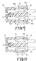
- the connector has rear holders which are first molded together with a housing in a plurality of molds. Then, the rear holders are temporarily retained in the housing as the molds are removed and. regularly retained therein after connecting terminals are inserted. And the present invention relates to a method of manufacturing thereof.
- rear holders 70a and 70b that are temporarily and regularly retained in such a manner as to be laid across opposite side portions of a housing 52 are held in the temporarily retaining positions.
- the housing has a plurality of terminal housing chambers 53. Then connecting terminals 32 are inserted from the rear end of the housing 52 and respectively retained by housing lances 81 in the terminal housing chambers 53. Further, the rear holders 70a and 70b are retained in the regularly retaining positions, so that the connecting terminals 32 are doubly retained therein.
- stooping guide holes 72 are provided in the respective side pieces of the rear holder 70a.
- Secondary retaining projections 73 for secondarily retaining each connecting terminal 32 are provided in the front end portion of the undersurface of the rear holder 70a. Openings 53a for inserting the secondary retaining projection 73 obliquely above from the temporarily retaining position to the regularly retaining position is provided in the upper central portion of each terminal housing chamber 53.
- a stooping guide rail 54 having a tapered surface engaged with the guide hole 72, and a regularly retaining projection 55 that is obliquely positioned in front of each guide rail 54.
- opposite sides 52b where the guide rails 54 and the regularly retaining projections 55 are projected, are set narrower than the whole width of the opposite sides 52a of the front portion, jutties 56 are set to opposite sides 52b in parallel to and below the guide rails 54 and the regularly retaining projections 55 whereby to make opposite sides 52b equal in width to opposite sides 52a. Because the lower rear holder 70b in the drawings is substantially equal in structure to the rear holder 70a, the description thereof will be omitted.
- the tapered surface provided on the surface of each guide rail 54 causes the side pieces 71 are bent to opposite directions when the rear holder 70a on one side is forced in from above the rear end portion of the housing 52.
- the guide holes 72 are mated with the guide rails 54, so that the rear holder 70a is held in the temporarily retaining position of the housing 52.
- the rear holder 70b is also held in the temporarily retaining position of the housing 52.
- the connecting terminal 32 When the connecting terminal 32 is subsequently inserted from behind the terminal housing chamber 53, it is primarily retained by the housing lance 81.
- the guide holes 72 are guided by the guide rail 54s and the front ends of the side pieces 71 climb over the regularly retaining projections 55. Then the front end portions of the guide holes 72 is retained by the regularly retaining projections 55 and the secondary retaining projections 73 are caused to enter the terminal housing chambers 53 from the openings 53a.
- housing 52 and the rear holders 70a and 70b are separately formed before being gathered at one place for the assembly of them, however, it becomes necessary carrying them to fabrication places and performing not only assembly but also inspection steps in addition to individually controlling such parts as housings 52 and rear holders 70a and 70b.
- a temporarily retaining mold 90 shown in Fig. 19 is formed with a front fixed mold (not shown), a first movable mold 92 that is moved vertically, a pair of second movable molds 93 and 93 that are moved laterally, and a pair of third movable molds 94 and 94 that are moved longitudinally.
- the central housing 52 in Fig. 19 is molded inside the first and second movable molds 92 and 93.
- the rear holders 70a and 70b are molded outside the first movable mold 92, inside the second movable mold 93 and inside the third movable mold 94.
- the housing 52 and the rear holders 70a and 70b are formed in such a condition that the fixed and the movable molds have been joined together and then the first movable mold 92 is pulled up and subsequently the second movable molds 93 and 93 are separated laterally. Consequently, a space is produced between the rear holders 70a and 70b and the housing 52, and the third movable molds 94 and 94 are moved in. the direction of the housing. Then the guide holes 72 of the rear holders 70a and 70b are retained by the guide rails 54 of the housing 52, and the rear holders 70a and 70b are temporarily retained by the housing 52. Further, the third movable molds 94 are separated from the housing 52, whereby the housing 52 in which the rear holders 70a and 70b have been retained temporarily is taken out of the temporarily retaining mold 90.
- Another problem is that the molding structure becomes complicated because it is necessary for the first movable mold 92 of the temporarily retaining mold 90 to move vertically, for the second movable molds 93 to move laterally and moreover for the third movable molds 94 to move longitudinally.
- An object of the present invention made in view of the foregoing problems is to provide an inexpensive connector with rear holders requiring no high dimensional precision in particular for the rear holders to be molded during molding operation for which employable movable molds need less moving.
- one of the rear holders includes the retaining hole and the retaining pawl having the stooping face inside the side piece of the rear holder; the temporarily retaining projection engaged with the retaining hole and having the tapered surface over its whole surface is provided on the side of the rear end portion of the housing, and the tapered retaining step engaged with the retaining pawl is provided in the vicinity of the temporarily retaining projection; the stooping contact face for guiding the rear holder is provided on the surface of the rear end portion of the housing; and the rear holders both are pivoted by respectively contacting the temporarily retaining projections and the retaining steps before being temporarily retained.
- the rear holders are temporarily retained in the housing while being pivoted when the retaining holes and the retaining pawls of the rear holders are brought into contact with the respective temporarily retaining projections and the retaining steps of the housing and when the undersurfaces of the rear holders are brought into contact with the contact faces.
- the retaining step and the contact face are pivoted on a relatively long slope, no high dimensional precision is essential, which makes it possible to not only improve productivity but also obtain an inexpensive connector with rear holders.
- the temporarily retaining mold for molding and temporarily retaining the housing and the rear holders includes the fixed mold and the plurality of movable molds which are movable with respect to the fixed mold; and after the housing and the rear holders are molded in the molds, the rear holders are pivoted and temporarily retained when at least one of the movable molds or part of the mold is subjected to parallel movement.
- the temporarily retaining mold for molding and temporarily retaining the housing and the rear holders includes the fixed mold, the first movable mold for forming the outer shell of the housing and the inner shells of the rear holders, the second movable molds for movably supporting the first movable mold in the axial direction of the housing, the third movable molds for forming the outer shells of the rear holders, and the fourth movable mold for forming and holding the central portion of the housing; and after the housing and the rear holders are molded in the mold, the second movable molds are estranged from the fixed mold and the first movable mold is moved back up to a position where the first movable mold holds the rear end portion of the housing, and the third movable molds are moved into the space produced inside the third movable molds, whereby the retaining holes of the rear holders are mated with the respective temporarily retaining projections; the rear holders are pivoted stoopingly on the temporarily retaining projection
- the first, second and fourth movable molds can be moved laterally only by vertically moving the third movable molds, a relatively simple structure and a driving method can be adopted, which makes it possible to not only improve productivity but also obtain an inexpensive connector with rear holders.
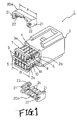
- Fig. 1 is an exploded perspective view of a female connector with rear holders as an embodiment of the invention.
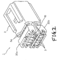
- Fig. 2 is a perspective view of the rear holders in Fig. 1 in a temporarily retained condition.
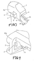
- Fig. 3 is a partially enlarged perspective view of the temporarily retained projection of the housing in Fig. 1.
- Fig. 4 is a partially enlarged perspective view of the side piece portion of the rear holder in Fig. 1.
- Fig. 5 is a sectional view of the rear holders in Fig. 1 in a temporarily retained condition.
- Fig. 6 is.a sectional view of the rear holders in Fig. 1 in a regularly retained condition.
- Fig. 7 is a sectional view of rear holders in a temporarily retained condition as another embodiment of the invention.
- Fig. 8 is a sectional view of the rear holders in Fig. 7 in a regularly retained condition.
- Fig. 9 is an exploded perspective view of a male connector with rear holders embodying the invention.
- Fig. 10 is a perspective view of the rear holders in Fig. 9 in a temporarily retained condition.
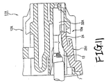
- Fig. 11 is a sectional view of rear holders in a temporarily retained condition as still another embodiment of the invention.
- Fig. 12 is a sectional view of the rear holders in Fig. 11 in a regularly retained condition.
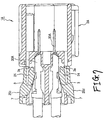
- Fig. 13 is a sectional view of a temporarily retaining mold for molding the connector with the rear holders during the process of injection molding.
- Fig. 14 is a sectional view of the temporarily retaining mold in Fig. 13 in its partially moved condition.
- Fig. 15 is a sectional view of the rear holders temporarily retained in the housing by the third movable molds in Fig. 13..
- Fig. 16 is an exploded perspective view of a connector with conventional rear holders by way of example.
- Fig. 17 is a sectional view of the rear holders in Fig. 16 in a temporarily retaining condition.
- Fig. 18 is a sectional view of the rear holders in Fig. 16 in a regularly retaining condition.
- Fig. 19 is a partial perspective view of a mold for temporarily retaining the rear holders in a housing after the connector with the rear holders in Fig. 16 is molded.
- FIG. 1 is an exploded perspective view of a female connector having rear holders as an embodiment of the invention.
- Fig. 2 is a perspective view of the rear holders in Fig. 1 in a temporarily retained condition.
- Fig. 3 is a partially enlarged perspective view of the temporarily retained projection of the housing in Fig. 1.
- Fig. 4 is a partially enlarged perspective view of the side piece portion of the rear holder in Fig. 1.
- Fig. 5 is a sectional view of the rear holders in Fig. 1 in a temporarily retained condition.
- Fig. 6 is a sectional view of the rear holders in Fig. 1 in a regularly retained condition.
- Fig. 7 is a sectional view of rear holders in a temporarily retained condition as another embodiment of the invention.
- Fig. 8 is a sectional view of the rear holders in Fig. 7 in a regularly retained condition.
- Fig. 9 is an exploded perspective view of a male connector with rear holders embodying the invention.
- Fig. 10 is a perspective view of the rear holders in Fig. 9 in a temporarily retained condition.
- Fig. 11 is a sectional view of rear holders in a temporarily retained condition as still another embodiment of the invention.
- Fig. 12 is a sectional view of the rear holders in Fig. 11 in a regularly retained condition.
- Fig, 13 is a sectional view of a temporarily retaining mold for molding the connector with the rear holders in Figs . 1 to 12 during the process of injection molding.
- Fig. 14 is a sectional view of the temporarily retaining mold in Fig. 13 in its partially moved condition.
- Fig. 15 is a sectional view of the rear holders temporarily retained in the housing by the third movable molds in Fig. 13.
- a female connector 1 having rear holders includes: a housing 2 having a plurality of terminal housing chambers 3; a rear holder 20a on the upper side of Fig. 1; a rear holder 20b on the lower side thereof; and a plurality of connecting terminals 30 to be inserted into the respective terminal housing chambers 3 (see Fig. 5).
- the rear holders 20a and 20b being temporarily and regularly retained in such a manner as to be laid across opposite side portions of the housing 2.
- a retaining hole 22 and a retaining pawl 23 having a forwardly and downwardly tilting face 23 are provided inside the side piece 21 of each of the rear holders 20a and 20b.
- a temporarily retaining projections 4 engaged with the retaining hole 22 and having a tapered surface 5 over the whole of its surface are provided on the opposite sides 2a of the rear end portion of the housing 2.
- a tapered retaining step 6 engaged with the retaining pawl 23 and tilting by an angle of ⁇ forwardly and downwardly with respect to the horizontal plane is provided on the side 2b that is continuous to the side 2a of the rear end portion above.
- a contact face 7 that tilts forwardly and downwardly and is used to hold and guide the undersurfaces of the rear holders 20a and 20b is provided on the surface of the rear end portion of the housing 2.
- a guide rail 8 in parallel to the retaining step 6 is provided below the retaining step.
- a regularly retaining projection 19 as a regularly retaining means is provided on the side the guide rail..
- a protective rib 10 having a width B is provided between the upper and lower terminal housing chambers 3 and 3 corresponding to the rear holders 20a and 20b as shown in Fig. 1. The width B is set greater than the width A of the rear holders 20a and 20b to prevent the rear holders 20a and 20b temporarily retained by the housing 2 within the mold from releasing and dropping from the mold.
- the retaining holes 22 are engaged with the respective temporarily retaining projections 4 when the rear holders 20a and 20b are pressed by movable molds as described later against the rear portion of the housing 2 formed in the temporarily retaining mold.
- the rear holders 20a and 20b are pivoted forward on the temporarily retaining projections 4.
- the retaining pawls 23 are engaged with the respective retaining steps 6.
- the undersurfaces of the rear holders 20a and 20b are brought into contact with the contact face 7. Whereby the rear holders 20a and 20b are temporarily retained in the housing 2 as shown in Fig. 2.
- a procedure for incorporating connecting terminals 30 into the connector 1 with the rear holders according to this embodiment of the invention is described as following.
- the rear holders 20a and 20b are held in a temporarily retaining position.
- the connecting terminals 30 are inserted into the terminal housing chamber 3 from the rear end of the housing so that the connecting terminals 30 are retain in the terminal housing chamber 3 by housing lances 31.
- the retaining pawls 23 are guided to the retaining steps 6 while the undersurfaces of the rear holders 20a and 20b are guided by the contact face 7 and moved forwardly due to pushing the rear holders 20a and 20b forwardly. Therefore, the retaining holes 22 are retained by a regularly retaining projection 9.
- the secondary retaining projections 24 of the rear holders 20a and 20b are allowed to enter openings 3a from the intermediate portion of the terminal housing chambers 3, whereby the connecting terminals 30 are doubly retained therein as shown in Fig. 6.
- the retaining hole 22 and the retaining pawl 23 having the forwardly downwardly tilting face 23 are provided inside the side piece 21 of each of the rear holders 20a and 20b.
- the temporarily retaining projection 4 engaged with the retaining hole 22 and having the tapered surface 5 over the whole of its surface is provided on the side 2a of the rear end portion of the housing 2.
- the tapered retaining step 6 engaged with the retaining pawl 23 is provided on the side 2b that is continuous to the side 2a of the rear end portion above.
- the contact face 7 tilting forwardly and downwardly for holding and guiding the undersurfaces of the rear holders 20a and 20b is provided on the surface of the rear end portion of the housing 2.
- the retaining holes 22 are respectively mated with the temporarily retaining projections 4, and the rear holders 20a and 20b are pivoted. Therefore, the retaining pawls 23 are engaged with the respective retaining steps 6, and the undersurfaces of the rear holders 20a and 20b are brought into contact with the contact face 7 with the effect of temporarily retaining the rear holders 20a and 20b.
- the retaining step 6 and the contact face 7 has a relatively long slope with the rear holders 20a and 20b being pivoted thereon, no high dimensional precision is essential, which makes it possible to not only improve productivity but also obtain an inexpensive connector with rear holders.
- the female connector with the rear holders described above is in such a form that the connecting terminals 30 are doubly retained by the rear holders 20a and 20b according to this embodiment of the invention, the invention is also applicable to a connector with rear holders without housing lances wherein connecting terminals are retained only by rear holders in terminal housing chambers.
- the connecting terminals 30A are inserted from the rear end of a housing 2A after rear holders 20c and 20d are held in a temporarily retained condition in the respective openings 3a in the side wall of the housing 2A as shown in Fig. 7.
- the connecting terminals are moved forward and downward before being regularly retained in the respective terminal housing chambers 3 and further retained by part of the retaining projection 24 of each of the rear holders 20c and 20d to prevent the connecting terminals 30A from slipping off backward.
- a male connector with rear holders embodying the invention will be described with reference to Figs. 9 and 10.
- Like reference characters in a connector 11 with rear holders designate like component parts of the aforementioned connector 1 with the rear holders and the detail description thereof will be omitted.
- the male connector 11 with rear holders includes: a housing 12 having a plurality of terminal housing chambers 13 and 14; rear holders 25a and 25b to be temporarily retained in such a manner to be laid vertically across both side portions of the housing; and a plurality of terminal housing chambers 30 to be inserted into the respective terminal housing chambers 13 and 14 (see Fig. 5).
- Openings 13a where the front end portion of the rear holder 25a enters are provided in the intermediate portion of the terminal housing chamber 13 on one side of the housing 12. Openings (not shown) are provided in the intermediate portion of the other terminal housing chamber 14.
- the terminal housing chambers 13 of the upper-stage housing 12 are provided over its whole width (four of them in Fig. 9). Only two terminal housing chambers 14 (as shown in Fig. 9) of the lower-stage are provided in opposite sides of the housing because the fitting lock means 16 is provided on the central portion of the lower-stage housing.
- a regular retaining step 19 as a regularly retaining means for regularly retaining the rear holders 25a and 25b in the housing 12 is provided on the front side of each retaining step 6. Since the tilting angle of the regularly retaining step 19 becomes parallel to the axis as shown in Fig. 6 when the rear holders 25a and 25b are regularly retained, that angle is set smaller than the tilting angle ⁇ ° of the retaining step 6. As the rest of the arrangement and the operation/working-effect are similar to those of the connector 1 with the rear holders described above, the description thereof will be omitted.
- the male connector 11 having the rear holders according to the above embodiment of the invention is in the form of doubly retaining the connecting terminals by the rear holders 25a and 25b, the invention is also applicable to a connector with rear holders without housing lances wherein connecting terminals are retained only by rear holders in terminal housing chambers.
- the connecting terminal 32A is inserted from the rear end of a housing 12A after a rear holder 25c is held in a temporarily retained condition in the opening 13a in the side wall of the housing 12A as shown in Fig. 11.
- the connecting terminal is moved forward downwardly before being regularly retained in the terminal housing chamber 13 and the front end portion of the retaining projection of the rear holder 25c prevents the connecting terminal 32A from slipping off backward.
- a temporarily retaining mold 40 for molding the housings 2 and 12 and the rear holders 20a, 20b, 25a and 25b includes a fixed mold having a gate (not shown).
- the movable molds include: a first mold 42 for forming the outer shells of the housings 2 and 12 and the inner shells of the rear holders 20a, 20b, 25a and 25b and for supporting a fourth movable mold (as will be described below) ; second movable molds 43 for supporting the first movable mold 42 movably in the axial direction of the housing and for supporting third movable molds (as will be described below) movably in a direction perpendicular to the axial direction thereof; the third movable molds 44 for forming the outer shells of the rear holders 20a, 20b, 25a and 25b; and the fourth movable mold 45 for forming and holding the central portions of the housings 2 and 12.
- compression springs 46 are provided between the first and second movable molds 42 and 43, so that the molds 42 and 43 are separated from each other by a distance of D or pushed and brought into contact with each other.
- the movable molds 42, 43, 44 and 45 are separated from the fixed mold 41 by a gap of C as shown in Fig.. 14 and simultaneously the first movable mold 42 is moved back by the compression springs 46 up to a position where the rear end portions of the molded housings 2 and 12 are held by the fourth movable mold 45, that is, by the distance of D.
- the third movable mold 44 is moved into the space 47 produced in the third movable mold 44 toward the housings 2 and 12 as shown in Fig. 15 and then retaining holes 22 of the molded rear holders 20a, 20b, 25a and 25b are mated with the respective temporarily retaining projections 4.
- the rear holders 20a, 20b, 25a and 25b are forwardly and downwardly pivoted on the temporarily retaining projections 4.
- the retaining pawls 23 are mated with the retaining steps 6, and the undersurfaces of the rear holders are brought into contact with the contact faces 7, whereby the rear holders 20a, 20b, 25a and 25b are temporarily retained in the housings 2 and 12.
- the rear holders 20a, 20b, 25a and 25b are temporarily retained in the housings 2 and 12, the rear holders 20a, 20b, 25a and 25b are discharged from the temporarily retaining mold 40.
- the protect ribs 10 having a width of B greater than the width A of the rear holders 20a, 20b, 25a and 25b are provided to the housings 2 and 12, the temporarily retained rear holders 20a, 20b, 25a and 25b are never removed from the housings 2 and 12 even though the rear holders are discharged and dropped from the mold.
- the temporarily retaining mold 40 As the first, second and fourth movable molds 42, 43 and 45 can be moved laterally only by vertically moving the third movable molds 44, it is possible to not only improve productivity but also obtain an inexpensive connector with rear holders that are relatively simple in structure.
- the driving structure and driving method of the temporarily retaining mold 40 is such that when the first movable mold 42, for example, is pressed by a fluid pressure cylinder or the like in the direction of the fixed mold 41, the closed condition of the mold is established as shown in Fig. 13.
- the first movable mold 42 is moved by the fluid pressure cylinder in the direction of estranging it from the fixed mold 41, the urging force of the compression springs 46.causes the first movable mold 42 to be separated from the second movable molds 43 by the distance of D and the third movable molds 44 are also separated from the fixed mold 41 by the gap of C as shown in Fig. 14. Consequently, it is ensured to set the gap C and the like by providing stoppers on the guide rails for slidably holding the second movable molds 43.
- the connectors having the rear holders according to the invention are not limited to the aforementioned mode for carrying it out but may be implemented in any other mode.
- the direction in which the third movable molds 44 of the temporarily retaining mold 40 are driven has been vertical in the methods according to this embodiment of the invention, they may be moved horizontally as long as they are movable in a direction perpendicular to the fitting axis of the housing.
- the connector having the rear holders according to the invention is such that one of the rear holders includes: the retaining hole and the retaining pawl having the forwardly and downwardly tilting face inside the side piece of the rear holder; the temporarily retaining projection engaged with the retaining hole and having the tapered surface over the whole of its surface, the tapered retaining step engaged with the retaining pawl in the vicinity of the temporarily retaining projection; and the contact face that tilts forwardly and downwardly and is used to guide the rear holder on the surface of the rear end portion of the housing, so that when the rear holders are pivoted when the rear holders are brought into contact with the temporarily retaining projections and the retaining steps, the rear holders are temporarily retained in the housing.
- the rear holders are temporarily retained in the housing while being pivoted when the retaining holes and the retaining pawlsof the rear holders are brought into contact with the respective temporarily retaining projections and the retaining steps of the housing and when the undersurfaces of the rear holders are brought into contact with the contact faces.
- the temporarily retaining mold for molding and temporarily retaining the housing and the rear holders includes the fixed mold and the plurality of movable molds which are movable with respect to the fixed mold; and after the housing and the rear holders are molded in the molds, the rear holders are pivoted and temporarily retained when at least one of the molds or some mold is run in parallel to another out of the movable molds.
- the temporarily retaining mold for molding and temporarily retaining the housing and the rear holders includes the fixed mold, the first movable mold for forming the outer shell of the housing and the inner shells of the rear holders, the second movable molds for movably supporting the first movable mold in the axial direction of the first movable mold, the third movable molds for forming the outer shells of the rear holders, and the fourth movable molds for forming and holding the central portion of the housing; and after the housing and the rear holders are molded in the molds, the second movable molds are estranged from the fixed mold and moved back up to the position where the first movable mold holds the rear end portion of the housing, and the third movable molds are moved into the space produced inside the third movable molds, whereby the retaining holes of the rear holders are mated with the respective temporarily retaining projections; each of the rear holders is pivoted forwardly and downwardly on the temporarily retaining projection; the
- the first, second and fourth movable molds can be moved laterally only by vertically moving the third movable molds, a relatively simple structure and a driving method can be adopted, which makes it possible to not only improve productivity but also obtain an inexpensive connector with rear holders.
Landscapes
- Connector Housings Or Holding Contact Members (AREA)
- Manufacturing Of Electrical Connectors (AREA)
Applications Claiming Priority (2)
| Application Number | Priority Date | Filing Date | Title |
|---|---|---|---|
| JP37097499A JP3690788B2 (ja) | 1999-12-27 | 1999-12-27 | リヤホルダ付きコネクタ及びその製造方法 |
| JP37097499 | 1999-12-27 |
Publications (3)
| Publication Number | Publication Date |
|---|---|
| EP1113535A2 true EP1113535A2 (de) | 2001-07-04 |
| EP1113535A3 EP1113535A3 (de) | 2002-06-12 |
| EP1113535B1 EP1113535B1 (de) | 2009-06-03 |
Family
ID=18497919
Family Applications (1)
| Application Number | Title | Priority Date | Filing Date |
|---|---|---|---|
| EP00311549A Expired - Lifetime EP1113535B1 (de) | 1999-12-27 | 2000-12-21 | Elektrischer Verbinder mit Kontaktverriegelungsteil und dessen Herstellungsverfahren |
Country Status (4)
| Country | Link |
|---|---|
| US (2) | US6435920B2 (de) |
| EP (1) | EP1113535B1 (de) |
| JP (1) | JP3690788B2 (de) |
| DE (1) | DE60042311D1 (de) |
Cited By (2)
| Publication number | Priority date | Publication date | Assignee | Title |
|---|---|---|---|---|
| WO2017009286A1 (de) * | 2015-07-13 | 2017-01-19 | Kostal Kontakt Systeme Gmbh | Mehrpoliges elektrisches steckverbinderteil und steckverbinderanordnung |
| EP4518037A1 (de) * | 2023-08-28 | 2025-03-05 | Rosenberger Hochfrequenztechnik GmbH & Co. KG | Steckverbindergehäuseanordnung und steckverbinder |
Families Citing this family (14)
| Publication number | Priority date | Publication date | Assignee | Title |
|---|---|---|---|---|
| JP3690785B2 (ja) * | 1999-08-24 | 2005-08-31 | 矢崎総業株式会社 | リヤホルダ付きコネクタ及びその製造方法 |
| JP2002124355A (ja) * | 2000-10-18 | 2002-04-26 | Yazaki Corp | コネクタハウジングとその製造方法 |
| JP3856752B2 (ja) * | 2002-10-31 | 2006-12-13 | 日本航空電子工業株式会社 | コネクタ及びその組立方法 |
| DE102007039307B4 (de) * | 2007-08-10 | 2012-02-23 | Itt Mfg. Enterprises, Inc. | Steckverbinder |
| JP2010067469A (ja) * | 2008-09-11 | 2010-03-25 | Sumitomo Wiring Syst Ltd | コネクタ |
| CN202111263U (zh) * | 2011-05-19 | 2012-01-11 | 泰科电子(上海)有限公司 | 电连接器 |
| JP5707252B2 (ja) * | 2011-06-24 | 2015-04-22 | 矢崎総業株式会社 | コネクタ |
| US8721374B2 (en) * | 2011-07-22 | 2014-05-13 | Lear Corporation | Electrical connector |
| US8951066B2 (en) | 2011-07-22 | 2015-02-10 | Lear Corporation | Electrical connector |
| JP5692421B1 (ja) * | 2014-01-10 | 2015-04-01 | 第一精工株式会社 | 電気コネクタ |
| JP6939400B2 (ja) * | 2017-10-24 | 2021-09-22 | 株式会社オートネットワーク技術研究所 | コネクタ、治具、及び端子のコネクタへの組み付け方法 |
| JP2019091560A (ja) * | 2017-11-13 | 2019-06-13 | 株式会社オートネットワーク技術研究所 | コネクタ、治具、及びコネクタの製造方法 |
| JP7390228B2 (ja) * | 2020-03-24 | 2023-12-01 | ヒロセ電機株式会社 | ケーブル保持体を備えるケーブルコネクタ、及び、このケーブルコネクタの製造方法 |
| JP2024053191A (ja) * | 2022-10-03 | 2024-04-15 | 株式会社オートネットワーク技術研究所 | コネクタ |
Citations (1)
| Publication number | Priority date | Publication date | Assignee | Title |
|---|---|---|---|---|
| EP0657964A1 (de) | 1993-12-09 | 1995-06-14 | SUMITOMO WIRING SYSTEMS, Ltd. | Verbinder mit integraler Kontaktverriegelung, Zuführ und Positioniereinrichtung und Verfahren zum Zuführen und Positionieren eines Verbinders |
Family Cites Families (8)
| Publication number | Priority date | Publication date | Assignee | Title |
|---|---|---|---|---|
| JP2789973B2 (ja) | 1992-11-06 | 1998-08-27 | 住友電装株式会社 | コネクタ |
| JP2964880B2 (ja) | 1994-08-03 | 1999-10-18 | 住友電装株式会社 | コネクタ |
| JP3000869B2 (ja) | 1994-11-07 | 2000-01-17 | 住友電装株式会社 | コネクタ |
| JP3000883B2 (ja) | 1995-03-13 | 2000-01-17 | 住友電装株式会社 | コネクタ |
| CN1091961C (zh) * | 1995-03-16 | 2002-10-02 | 住友电装株式会社 | 有止动器的连接器组件及制造该连接器组件的方法和模具 |
| US5915760A (en) * | 1995-03-16 | 1999-06-29 | Sumitomo Wiring Systems, Ltd. | Method of producing resin-molded product |
| JP3266782B2 (ja) * | 1995-06-05 | 2002-03-18 | 矢崎総業株式会社 | リヤホルダー付きコネクタの製造方法 |
| JP3301329B2 (ja) * | 1996-12-27 | 2002-07-15 | 住友電装株式会社 | コネクタ |
-
1999
- 1999-12-27 JP JP37097499A patent/JP3690788B2/ja not_active Expired - Fee Related
-
2000
- 2000-12-21 DE DE60042311T patent/DE60042311D1/de not_active Expired - Lifetime
- 2000-12-21 EP EP00311549A patent/EP1113535B1/de not_active Expired - Lifetime
- 2000-12-27 US US09/748,383 patent/US6435920B2/en not_active Expired - Lifetime
-
2001
- 2001-09-20 US US09/956,035 patent/US6699420B2/en not_active Expired - Lifetime
Patent Citations (1)
| Publication number | Priority date | Publication date | Assignee | Title |
|---|---|---|---|---|
| EP0657964A1 (de) | 1993-12-09 | 1995-06-14 | SUMITOMO WIRING SYSTEMS, Ltd. | Verbinder mit integraler Kontaktverriegelung, Zuführ und Positioniereinrichtung und Verfahren zum Zuführen und Positionieren eines Verbinders |
Cited By (4)
| Publication number | Priority date | Publication date | Assignee | Title |
|---|---|---|---|---|
| WO2017009286A1 (de) * | 2015-07-13 | 2017-01-19 | Kostal Kontakt Systeme Gmbh | Mehrpoliges elektrisches steckverbinderteil und steckverbinderanordnung |
| US10050381B2 (en) | 2015-07-13 | 2018-08-14 | Kostal Kontakt Systeme Gmbh | Plug connector having housing parts having channels with spring tongues for fixing plug contacts within the channels |
| EP4518037A1 (de) * | 2023-08-28 | 2025-03-05 | Rosenberger Hochfrequenztechnik GmbH & Co. KG | Steckverbindergehäuseanordnung und steckverbinder |
| WO2025045412A1 (de) | 2023-08-28 | 2025-03-06 | Rosenberger Hochfrequenztechnik Gmbh & Co. Kg | Steckverbindergehäuseanordnung und steckverbinder |
Also Published As
| Publication number | Publication date |
|---|---|
| DE60042311D1 (de) | 2009-07-16 |
| US6699420B2 (en) | 2004-03-02 |
| EP1113535A3 (de) | 2002-06-12 |
| US6435920B2 (en) | 2002-08-20 |
| EP1113535B1 (de) | 2009-06-03 |
| US20010005657A1 (en) | 2001-06-28 |
| JP2001185276A (ja) | 2001-07-06 |
| JP3690788B2 (ja) | 2005-08-31 |
| US20020013105A1 (en) | 2002-01-31 |
Similar Documents
| Publication | Publication Date | Title |
|---|---|---|
| EP1113535B1 (de) | Elektrischer Verbinder mit Kontaktverriegelungsteil und dessen Herstellungsverfahren | |
| EP0590496B1 (de) | Steckvorrichtung | |
| US20070207647A1 (en) | Connector, connector assembly and assembling method | |
| US6655999B2 (en) | Connector and a method of assembling it | |
| US5709831A (en) | Method of producing connector with rear holder | |
| JP2005216813A (ja) | 分割コネクタ | |
| JP2003007388A (ja) | コネクタ | |
| EP1085617A1 (de) | Verbinder | |
| EP0822617A2 (de) | Elektrischer Steckverbinder | |
| JP4304474B2 (ja) | コネクタ | |
| EP1162704B1 (de) | Verbinder und Verfahren zum Trennen von Gehäusen | |
| EP1079469B1 (de) | Von hinten angebrachte Kontakthalterung für Verbinder und dessen Herstellungsverfahren | |
| JP2005019282A (ja) | コネクタ | |
| KR100709086B1 (ko) | 분리 커넥터 및 그 조립 방법 | |
| EP1164663B1 (de) | Befestigungstruktur eines Verbindergehäuses und einer von hinten angebrachten Kontakthalterung | |
| JP3625166B2 (ja) | 成形仮係止金型及び成形仮係止方法 | |
| JP6730975B2 (ja) | 電気コネクタ及び該電気コネクタ内の接続端子の係止方法 | |
| JP4383358B2 (ja) | コネクタハウジングの成形方法及びコネクタハウジング | |
| JP4228848B2 (ja) | リテーナ付き端子収容部材、及び治具 | |
| JP3225783B2 (ja) | コネクタの製造方法 | |
| US20050029710A1 (en) | Mold tooling having improved cavity stabilizers | |
| JP2021026806A (ja) | コネクタ用ハウジング、及びコネクタ用ハウジングの製造方法 | |
| JPH08273741A (ja) | コネクタ | |
| JP2004022307A (ja) | コネクタ | |
| JPH1055844A (ja) | 電気コネクタ |
Legal Events
| Date | Code | Title | Description |
|---|---|---|---|
| PUAI | Public reference made under article 153(3) epc to a published international application that has entered the european phase |
Free format text: ORIGINAL CODE: 0009012 |
|
| AK | Designated contracting states |
Kind code of ref document: A2 Designated state(s): AT BE CH CY DE DK ES FI FR GB GR IE IT LI LU MC NL PT SE TR |
|
| AX | Request for extension of the european patent |
Free format text: AL;LT;LV;MK;RO;SI |
|
| PUAL | Search report despatched |
Free format text: ORIGINAL CODE: 0009013 |
|
| AK | Designated contracting states |
Kind code of ref document: A3 Designated state(s): AT BE CH CY DE DK ES FI FR GB GR IE IT LI LU MC NL PT SE TR |
|
| AX | Request for extension of the european patent |
Free format text: AL;LT;LV;MK;RO;SI |
|
| 17P | Request for examination filed |
Effective date: 20021119 |
|
| AKX | Designation fees paid |
Designated state(s): DE FR GB |
|
| RAP1 | Party data changed (applicant data changed or rights of an application transferred) |
Owner name: YAZAKI CORPORATION |
|
| 17Q | First examination report despatched |
Effective date: 20080401 |
|
| GRAP | Despatch of communication of intention to grant a patent |
Free format text: ORIGINAL CODE: EPIDOSNIGR1 |
|
| RIN1 | Information on inventor provided before grant (corrected) |
Inventor name: KASHIYAMA, MOTOHISA, |
|
| GRAS | Grant fee paid |
Free format text: ORIGINAL CODE: EPIDOSNIGR3 |
|
| GRAA | (expected) grant |
Free format text: ORIGINAL CODE: 0009210 |
|
| AK | Designated contracting states |
Kind code of ref document: B1 Designated state(s): DE FR GB |
|
| REG | Reference to a national code |
Ref country code: GB Ref legal event code: FG4D |
|
| REF | Corresponds to: |
Ref document number: 60042311 Country of ref document: DE Date of ref document: 20090716 Kind code of ref document: P |
|
| PLBE | No opposition filed within time limit |
Free format text: ORIGINAL CODE: 0009261 |
|
| STAA | Information on the status of an ep patent application or granted ep patent |
Free format text: STATUS: NO OPPOSITION FILED WITHIN TIME LIMIT |
|
| 26N | No opposition filed |
Effective date: 20100304 |
|
| REG | Reference to a national code |
Ref country code: FR Ref legal event code: PLFP Year of fee payment: 16 |
|
| REG | Reference to a national code |
Ref country code: FR Ref legal event code: PLFP Year of fee payment: 17 |
|
| REG | Reference to a national code |
Ref country code: FR Ref legal event code: PLFP Year of fee payment: 18 |
|
| PGFP | Annual fee paid to national office [announced via postgrant information from national office to epo] |
Ref country code: DE Payment date: 20191210 Year of fee payment: 20 |
|
| PGFP | Annual fee paid to national office [announced via postgrant information from national office to epo] |
Ref country code: FR Payment date: 20191115 Year of fee payment: 20 |
|
| PGFP | Annual fee paid to national office [announced via postgrant information from national office to epo] |
Ref country code: GB Payment date: 20191219 Year of fee payment: 20 |
|
| REG | Reference to a national code |
Ref country code: DE Ref legal event code: R071 Ref document number: 60042311 Country of ref document: DE |
|
| REG | Reference to a national code |
Ref country code: GB Ref legal event code: PE20 Expiry date: 20201220 |
|
| PG25 | Lapsed in a contracting state [announced via postgrant information from national office to epo] |
Ref country code: GB Free format text: LAPSE BECAUSE OF EXPIRATION OF PROTECTION Effective date: 20201220 |