EP1113524B1 - Antennenstruktur, Verfahren zur Kopplung eines Signals an die Antennenstruktur, Antenneneinheit und Mobilstation mit einer derartigen Antennenstruktur - Google Patents
Antennenstruktur, Verfahren zur Kopplung eines Signals an die Antennenstruktur, Antenneneinheit und Mobilstation mit einer derartigen Antennenstruktur Download PDFInfo
- Publication number
- EP1113524B1 EP1113524B1 EP00660228A EP00660228A EP1113524B1 EP 1113524 B1 EP1113524 B1 EP 1113524B1 EP 00660228 A EP00660228 A EP 00660228A EP 00660228 A EP00660228 A EP 00660228A EP 1113524 B1 EP1113524 B1 EP 1113524B1
- Authority
- EP
- European Patent Office
- Prior art keywords
- antenna element
- antenna
- ground plane
- radio system
- antenna structure
- Prior art date
- Legal status (The legal status is an assumption and is not a legal conclusion. Google has not performed a legal analysis and makes no representation as to the accuracy of the status listed.)
- Expired - Lifetime
Links
Images


Classifications
-
- H—ELECTRICITY
- H01—ELECTRIC ELEMENTS
- H01Q—ANTENNAS, i.e. RADIO AERIALS
- H01Q9/00—Electrically-short antennas having dimensions not more than twice the operating wavelength and consisting of conductive active radiating elements
- H01Q9/04—Resonant antennas
- H01Q9/0407—Substantially flat resonant element parallel to ground plane, e.g. patch antenna
- H01Q9/0442—Substantially flat resonant element parallel to ground plane, e.g. patch antenna with particular tuning means
-
- H—ELECTRICITY
- H01—ELECTRIC ELEMENTS
- H01Q—ANTENNAS, i.e. RADIO AERIALS
- H01Q1/00—Details of, or arrangements associated with, antennas
- H01Q1/12—Supports; Mounting means
- H01Q1/22—Supports; Mounting means by structural association with other equipment or articles
- H01Q1/24—Supports; Mounting means by structural association with other equipment or articles with receiving set
- H01Q1/241—Supports; Mounting means by structural association with other equipment or articles with receiving set used in mobile communications, e.g. GSM
- H01Q1/242—Supports; Mounting means by structural association with other equipment or articles with receiving set used in mobile communications, e.g. GSM specially adapted for hand-held use
- H01Q1/243—Supports; Mounting means by structural association with other equipment or articles with receiving set used in mobile communications, e.g. GSM specially adapted for hand-held use with built-in antennas
-
- H—ELECTRICITY
- H01—ELECTRIC ELEMENTS
- H01Q—ANTENNAS, i.e. RADIO AERIALS
- H01Q21/00—Antenna arrays or systems
- H01Q21/28—Combinations of substantially independent non-interacting antenna units or systems
-
- H—ELECTRICITY
- H01—ELECTRIC ELEMENTS
- H01Q—ANTENNAS, i.e. RADIO AERIALS
- H01Q21/00—Antenna arrays or systems
- H01Q21/30—Combinations of separate antenna units operating in different wavebands and connected to a common feeder system
-
- H—ELECTRICITY
- H01—ELECTRIC ELEMENTS
- H01Q—ANTENNAS, i.e. RADIO AERIALS
- H01Q9/00—Electrically-short antennas having dimensions not more than twice the operating wavelength and consisting of conductive active radiating elements
- H01Q9/04—Resonant antennas
- H01Q9/0407—Substantially flat resonant element parallel to ground plane, e.g. patch antenna
- H01Q9/0421—Substantially flat resonant element parallel to ground plane, e.g. patch antenna with a shorting wall or a shorting pin at one end of the element
-
- H—ELECTRICITY
- H01—ELECTRIC ELEMENTS
- H01Q—ANTENNAS, i.e. RADIO AERIALS
- H01Q9/00—Electrically-short antennas having dimensions not more than twice the operating wavelength and consisting of conductive active radiating elements
- H01Q9/04—Resonant antennas
- H01Q9/0407—Substantially flat resonant element parallel to ground plane, e.g. patch antenna
- H01Q9/0428—Substantially flat resonant element parallel to ground plane, e.g. patch antenna radiating a circular polarised wave
Definitions
- the present invention relates to small-sized microstrip antennas that operate on many different frequency bands.
- the invention relates to internal antennas used in mobile phones, which are fed from one feeding point.
- a frequency range comprises one or more frequency bands, i.e. a frequency band is part of the frequency range.
- reception band is meant a frequency band reserved for downlink data transmission
- transmission band is meant a frequency band reserved for uplink data transmission.
- Dual band terminals have been implemented by both an external and internal antenna.
- the external antenna which can be, for example, monopole, helix or their combination, is demanding as for its manufacturing technique, and it breaks easily. Therefore, in mobile stations, there is going on an increasing changeover to internal antenna structures implemented by microstrip antennas.
- the advantage of internal antennas compared to external antennas is the ease of the manufacturing technique and the speeding up of the serial production as the degree of integration increases, as well as the more durable structure than that of the external antennas.
- a conventional microstrip antenna comprises a ground plane and a radiating antenna element that is insulated from the ground plane by an insulating layer.
- the resonance frequency of the microstrip antenna is determined on the basis of the physical dimensions of the antenna element and the distance between the antenna element and the ground plane.
- the operating principle and dimensioning of microstrip antennas are well known and they are described in the literature relating to the field.
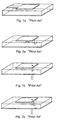
- FIGS 1a and 1b show a microstrip antenna and an L-plane antenna according to prior art, which hereinafter in the present patent application will be called an L-antenna.
- the microstrip antenna consists of a ground plane, a radiating antenna element, as well as a feeding line. In between and above the ground plane and the antenna element, there is either air or some other dielectric agent as an insulating material.
- the L-antenna is a whip antenna that is bent near the ground plane parallel to the ground plane, whereupon the antenna has a low feed impedance. It is also possible to build of the L-antenna a microstrip antenna that consists of a ground plane, a radiating antenna element as well as a feeding line.
- the length of the resonant proportion of the antenna in wavelengths is defined as the difference between the microstrip antenna and the L-antenna.
- the electric length of the microstrip antenna is half a wavelength whereas, traditionally, the electric length of the L-antenna is a quarter of a wavelength. From the electric length of the L-antenna it follows that the maximum current of the L-antenna is at the input.
- the microstrip antenna is made on a double-sided substrate, one metallisation of which acts as the ground plane and on the other, the pattern of the antenna element is made by etching.
- the antenna element is fed by the feeding line, which is coupled to the antenna element either from one side ( Figure 1 a) or by taking the feeding line through the ground plane and the insulating material ( Figure 1b).
- the resonance frequency of the microstrip and L-antennas is affected by the physical dimensions of the antenna element, the place of the feeding point, as well as, to some extent, the location of the antenna element with respect to the ground plane.
- the size of the microstrip antenna has been reduced by developing a so-called PIFA antenna (PIFA, Planar Inverted F-Antenna), shown in Figure 2b.
- PIFA Planar Inverted F-Antenna
- the antenna element is coupled to the ground plane by a grounding line.
- the actual antenna element can be dimensioned so that it is considerably smaller than in the case of the microstrip antenna.
- the feed impedance of the antenna can be changed to the desired impedance level, which is not possible in the L-antenna.
- the resonance frequency of the PIFA antenna is affected by the physical dimensions of the antenna element and the ground plane, as well as by the distance of the antenna element from the ground plane.
- the antenna element is fed either from one side (Figure 2a) or by taking the feeding line through the ground plane and the insulating material ( Figure 2b).
- Figure 2a When narrowing the width of the grounding line, the resonance frequency of the antenna decreases.
- the grounding line can be as wide as the whole antenna element or, at its narrowest, merely a conductor.
- a microstrip antenna capacitively there is a feeding element in between the antenna element and the ground plane, whereupon a capacitive coupling is formed between the antenna element and the feeding element.
- the feeding line is coupled to the feeding element, which radiates power further to the antenna element.
- the capacitive coupling can be implemented both in the microstrip antenna ( Figure 3) and the PIFA antenna ( Figure 4).
- microstrip antennas The problem of microstrip antennas is the narrow bandwidth.
- the frequency ranges of 2 nd generation mobile communication systems are reasonably narrow and, therefore, they can be implemented by microstrip antennas.
- the frequency range of the GSM system is 890 - 960 MHz, wherein a transmission band is 890 - 915 MHz and a reception band is 935 - 960 MHz.
- the bandwidth required of one antenna element is no less than 70 MHz. Due to the production tolerances and the objects in the vicinity of the antenna, for example, the hand of a user, the bandwidth of the antenna element must be even wider.
- the frequency ranges required by 3 rd generation mobile communication systems, for example, broadband CDMA systems are still considerably wider than, for example, the GSM system's and, therefore, their implementation with microstrip antennas is difficult.
- a transmission band of the WCDMA system is 1920 - 1980 MHz and a reception band is 2110 - 2170 MHz. This being the case, the whole width of the frequency range is 250 MHz. This is why the bandwidth of microstrip antennas according to prior art described above has been increased as far as possible with solutions, where several resonance frequencies close to each other are implemented in one antenna element.
- an antenna structure of two frequency ranges can be implemented by one common feeding point and an antenna element the resonance frequency of which can be adjusted by a switch and an electric load to the frequency range of another mobile communication system.
- a second alternative is to use one antenna element and two separate feeding points, whereupon two different resonance frequencies are generated in the antenna element.
- a third alternative is to use two antenna elements, which are coupled to a common feeding point. In this case, both antenna elements have one resonance frequency.
- Figure 5 shows a PIFA antenna of two frequency ranges according to prior art, which is fed from one feeding point.
- the resonance frequency of the antenna element is adjusted either by coupling in between the antenna element and the ground plane an electric load.
- the load can also be coupled as part of the feeding line.
- the load can be some reactive component, for example, a capacitance or inductance.
- the size of the change in the resonance frequency is determined on the basis of the electric load.
- a solution according to Figure 5 is described, for example, in the publication "Electrical Tuning of Integrated Mobile Phone Antennas," Louhos, J-P, Pankinaho, I, Proceedings of The 1999 Antenna Applications Symposium, Allerton Park, Monticello, Illinois, September 15-17,1999.
- the antenna element is dimensioned so that the first resonance frequency is selected from the reception band of the GSM900 system.
- the resonance frequency is adjusted to a lower resonance frequency by coupling the capacitive load C with a switch S between the antenna element and the ground plane, whereupon the resonance frequency of the antenna element changes to the transmission band of the GSM900 system.
- Figures 6 and 7 describe the antenna structures described in the publication "Dual Frequency Planar Inverted F-Antenna” (Liu Z., et al., IEEE Transactions on Antennas & Propagation, No. 10, October 1997, pages 1451 -1458), wherein two resonance frequencies are implemented in one PIFA antenna.
- a part E2 is separated, which is dimensioned for a higher frequency range.
- the first antenna element E1 is fed from a feeding point F1 and the second antenna element E2 is fed from a second feeding point F2.
- Both antenna elements are grounded and dimensioned so that they have different resonance frequencies.
- a plurality of ground pins G1, G2 are used.
- the antenna elements' polarisations are the same.
- the antenna elements are coupled to each other, whereupon one antenna element E3 is formed, which is fed from one feeding point F3.
- one antenna element E3 is formed, which is fed from one feeding point F3.
- a plurality of ground pins G3, G4, G5 are used.
- the dimensioning of the antenna elements becomes considerably more difficult, because the antenna elements are coupled to the same feeding point and the antenna elements' gain, impedance and bandwidths depend on each other. Also in this solution, the antenna elements' polarisations are the same.
- the advantage of one feeding point compared to solutions of a plurality of feeding points is that the manufacturing of the antenna elements becomes easier and the need for contact surfaces decreases. The required area also becomes smaller. In addition, production, operators and the authorities want to measure the operation of an antenna, as well as the strength and quality of the signal transmitted and received by a mobile phone from one feeding point.
- the biggest problem is the inter-coupling of the antenna elements, which impairs the radiation efficiency of the antenna structure. Due to the inter-coupling of the antenna elements, from the antenna element that operates at a first frequency range, power is coupled to the antenna element of a second frequency range and vice versa. Therefore, in the solutions of several antenna elements in question, the harmful inter-coupling of antenna elements must be reduced in order to achieve good radiation efficiency.
- the antenna elements are parallel to the ground plane, whereupon the coupling between the antenna elements and the ground plane is highly capacitive.
- the capacitive coupling in turn follows that the antenna elements are unilateral.
- the transmitting antennas used in mobile stations should be unilateral, whereas their receiving antennas should be as isotropic, i.e. omnidirectional as possible.
- the antenna structure according to Figure 5 operates well when information is transmitted from a mobile station to a base transceiver station, but information transmitted by the base transceiver station should be received in all the different operating positions of the phone.
- the solutions are implemented in the GSM system, i.e. with reasonably narrow bandwidths.
- the antenna elements are unilateral, whereupon they do not necessarily operate sufficiently well when receiving a broadband signal.
- the problem with the antenna structure of two antenna elements fed from one feeding point is, in addition to those mentioned above, also the inter-coupling of the antenna elements.
- microstrip antennas Due to the factors mentioned above, by microstrip antennas according to prior art, it has neither been possible to implement an antenna structure comprising one feeding point that would operate optimally enough in both 2 nd and 3 rd generation mobile stations.
- Document GB 2 317 994 discloses a multi-resonant antenna with conductive antenna elements extending perpendicularly from the ground plane.
- an antenna structure fed from one feeding point that operates on several different frequency bands with which in addition to a good bandwidth also unilaterality in transmitting and isotropy in receiving is achieved is implemented in a new way.
- the antenna structure's gain and radiation efficiency are made good by reducing the interfering inter-coupling of the antenna elements.
- the space required by the whole antenna structure is smaller compared to the antennas of a corresponding frequency range. Consequently, it is easy to position an antenna structure according to the invention, for example, inside a mobile phone or an antenna unit to be coupled to a mobile phone.
- the objectives of the invention are achieved by both a new frequency band solution and a new positioning of antenna elements, which enables the implementation of an antenna structure that operates on a broad band.
- the antenna's transmitting antenna element of a lower frequency range is more unilateral than the receiving antenna element of a higher frequency range.
- the positioning of antenna elements according to the invention reduces the inter-coupling between at least two antenna elements, whereupon the antenna structure's gain and radiation efficiency become good.
- the basic idea of the invention is to use, instead on one transmitting and receiving antenna element, two antenna elements coupled to each other with a coupling line so that a first antenna element is used to receive information from a reception band of a first radio system and a second antenna element is used to transmit information on a transmission band of the first radio system.
- the first reception band is a reception band of some broadband CDMA system of a 3 rd mobile station generation and the first transmission band is a transmission band of the same broadband CDMA system.
- the antenna structure is made to operate on a broad band and it is possible to operate in a broad frequency range.
- the antenna elements are positioned so that the first antenna element, which preferably is a receiving antenna element, is on the side of the ground plane and perpendicular to the ground plane and the second antenna element, which preferably is a transmitting antenna element, is in turn above the ground plane and parallel to the ground plane.
- the first antenna element can be made omnidirectional and the second antenna element unilateral. There is also little harmful inter-coupling between the antenna elements, whereupon a good gain and radiation efficiency are achieved by the antenna structure.
- Harmful inter-coupling can be further reduced by designing the polarisations of the first and second antenna elements to differ from each other, whereupon a good polarisation attenuation is produced between the antenna elements.
- the efficiency and omnidirectionality of the antenna can be improved on the reception band.
- This can be best implemented so that the open end of the first antenna element is located in the vicinity of the upper edge of the printed board, whereupon the electric fields of the antenna and the ground plane are strongly coupled to each other at the "open" end of both radiators.
- the antenna element acts as a feeding element for the ground plane, which acts as a main radiator.
- the coupling between the second antenna element and the ground plane can again be reduced by placing the second antenna element on the ground plane so that the open end, feeding point and ground point of the second antenna element are located more in the centre of the ground plane.
- the antenna structure can be placed in a mobile station that has, for example, a camera and a GPS antenna.
- the adaptation of the first antenna element can be improved further by designing a coupling line connecting the antenna elements from the input to the second antenna element and a grounding line reaching from the second antenna element to the ground so that their common electric length is a quarter of a wavelength at the resonance frequency of the first antenna.
- the first antenna element sees the grounding in question as open and the antenna operates more efficiently as a monopole-type (e.g. folded monopole) antenna.
- the grounding line of the first antenna element is slightly shorter than a quarter of a wavelength, its effect is smaller on the adaptation of the first antenna element than on the adaptation of the second antenna element and, thus, the capacitance of the first antenna element with respect to the ground plane is lower in the optimum location of the first antenna element so that radiation resistance and feed impedance of the first antenna element are sufficiently high.
- the second antenna element is arranged to also operate in the frequency range or part of the frequency range of a second mobile communication system.
- an antenna structure can be implemented, wherein by the first antenna element a reception band of a broadband radio system is implemented.
- the second antenna element both a transmission band of a broadband radio system and at least one transmission band of a second radio system, which is e.g. a transmission band, a reception band or both of the GSM1800 or GSMA1900 system, are implemented.
- the antenna structure according the invention it is possible to implement an antenna structure that operates both in 2 nd and 3 rd generation mobile communication systems.
- the antenna elements do not significantly impair each other's properties, whereupon it is easy to add to the same feeding point antenna elements that operate below and above the first transmission band.
- the operation of the antenna structure according to the invention can be extended, for example, into the frequency ranges of the GSM900 or PDC800 systems by using antenna elements dimensioned for the frequency ranges in question.
- the adding of antenna elements that operate above the first frequency range is even easier, because as the frequencies increase, the size of the antenna elements becomes smaller.
- It is easy to implement in the antenna structure for example, at least one of the antenna elements of the following systems: Bluetooth, WLAN (Wireless Local Area Network) or GPS (Global Positioning System).
- an antenna structure which comprises a first antenna element, a second antenna element, a ground plane for grounding the antenna structure, a coupling line for coupling the first antenna element and the second antenna element to each other, and a feeding line coupled to the coupling line for feeding the antenna structure through one feeding point, the first antenna element is next to the ground plane and perpendicular to the ground plane and the second antenna element is above the ground plane and parallel to the ground plane, and the second antenna element is capacitively coupled to the ground plane.
- a method for coupling a signal to an antenna structure which comprises a first antenna element, a second antenna element, a ground plane for grounding the antenna structure, a coupling line for coupling the first antenna element and the second antenna element to each other, a feeding line coupled to the coupling line for feeding the antenna structure, and which method comprises coupling signals to be transmitted and received to the antenna structure through one feeding point, the method comprising positioning the first antenna element next to the ground plane and perpendicular to the ground plane and positioning the second antenna element above the ground plane parallel to the ground plane, and coupling the second antenna element to the ground plane.
- an antenna unit which comprises an antenna structure, which antenna structure comprises a first antenna element, a second antenna element, a ground plane for grounding the antenna structure, a coupling line for coupling the first antenna element and the second antenna element to each other, and a feeding line for feeding the antenna structure through one feeding point, and which antenna structure is manufactured on an insulating material which has a base and at least one wall region, which wall region reaches in a direction deviating from the base, and the shape of which antenna structure follows the shapes of the base and the wall region, and in which antenna structure the first antenna element is next to the ground plane and perpendicular to the ground plane and the second antenna element is above the ground plane and parallel to the ground plane, and the second antenna element is grounded with a grounding line and capacitively coupled to the ground plane.
- a mobile station which comprises an antenna structure, which antenna structure comprises a first antenna element, a second antenna element, a ground plane for grounding the antenna structure, a coupling line for coupling the first antenna element and the second antenna element to each other, and a feeding line coupled to the coupling line for feeding the antenna structure through one feeding point, and in which antenna structure the first antenna element is next to the ground plane and perpendicular to the ground plane and the second antenna element is above the ground plane and parallel to the ground plane, and the second antenna element is grounded with the grounding line and capacitively coupled to the ground plane.
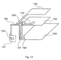
- Figures 8a, 8b and 8c show the antenna structure 100 according to the invention viewed from above, from one side and from the front respectively.
- Figure 9 in turn shows the antenna structure 100 according to the invention three-dimensionally.
- the antenna structure 100 consists of a first antenna element 101, a second antenna element 102, a ground plane 105, a coupling line 106 that connects the antenna elements, a feeding line 107 and a grounding line 108, which is coupled from the second antenna element 102 to the ground plane 105. Further, the first antenna element 101 comprises a first tuning slot 109 and the second antenna element comprises a second tuning slot 110.
- the antenna structure according to the invention consists of a microstrip antenna and a PIFA antenna coupled to each other with the feeding line of the L-antenna.
- the feeding point of the antenna structure is on the connection of the feeding line of the microstrip antenna and the PIFA antenna or in the immediate vicinity of the connection.
- the microstrip antenna and the PIFA antenna also have tuning slots.
- the coupling line 106, the feeding line 107 and the grounding line 108 are preferably microstrips, but other conductors known to a person skilled in the art can also be used.
- the second antenna element 102 is a quadrangular plane, parallel to the ground plane. From the corner formed by a first and second side of the plane, there starts the coupling line 106 that continues away from the second antenna element 102 and bends towards the ground plane 105 so that it substantially deviates from the plane of the second antenna element 102.
- the coupling line 106 is reasonably narrow compared to the lengths of the sides of the second antenna element 102. The length of the coupling line depends on the electric lengths of the desired resonance frequency.
- the first antenna element 101 is at the end of the coupling line 106 and perpendicular to the ground plane.
- the first antenna element 101 is a quadrangular plane, which has two shorter and two longer sides.
- the first antenna element 101 starts from the end of the coupling line 106 so that the longer sides are parallel to the ground plane 105 and the shorter sides are perpendicular to the ground plane 105.
- the first antenna element 101 bends towards the second antenna element 102, parallel to the first side of the second antenna element 102.
- the first antenna element By the first antenna element, the upper part of the frequency range of a broadband radio system (e.g. a reception band of the WCDMA system) is implemented and by the second antenna element, the lower part of a broadband radio system (e.g. a transmission band of the WCDMA system) is implemented.
- the sides of the first antenna element 101 are shorter than the sides of the second antenna element 102, whereupon the first antenna element 101 operates on a shorter wavelength, i.e. at a higher resonance frequency. Consequently, the area of the first antenna element 101 is smaller than the area of the second antenna element 102.
- the first antenna element is coupled to the ground plane 105 less capacitively than the second antenna element 102.
- the polarisations of the antenna elements can be designed to differ from each other.
- the first antenna element 101 is, for example, elliptically polarised and the second antenna element 102 more linearly polarised.
- the second antenna element 102 can be elliptically polarised and the first antenna element 101 more linearly polarised.
- Linear polarisations that differ from each other can also be used.
- one of the antenna elements is, for example, horizontally and the other is vertically polarised.
- the polarisation of the antenna elements can be affected by positioning the antenna elements in directions that deviate from each other with respect to the ground plane.
- the place of the feeding point of the antenna elements with respect to the second antenna element also influences the polarisation of which antenna element is primarily affected by the ground plane.
- the antenna structure 100 is fed from the corner formed by the feeding line 106 and the second side of the second antenna element 102 or from its immediate vicinity.
- the feeding line 107 is coupled to the coupling line 106.
- the feeding line 107 deviates from the plane of the second antenna element 102 and bends towards the ground plane 105.
- a transceiver is coupled to the end of the feeding line 107.
- a transmitted signal is coupled from the transceiver to the end of the feeding line 107, from where the power of the transmitted signal is further coupled through the feeding line 107 to the antenna structure 100.
- the power of the received signal is coupled to the antenna structure 100, from where the power of the received signal is coupled through the feeding line 107 to the end of the feeding line 107 and further to the transceiver.
- a peak value of the current distribution of the antenna structure is generated at the resonance frequency of the first antenna element 101, whereupon the current distribution of the antenna structure and further the resonance frequency, the feed impedance and the radiation pattem are affected by the positioning and dimensioning of the feeding line.
- grounding line 108 From the second side of the second antenna element 102, there starts the grounding line 108, which is coupled to the ground plane 105. At the resonance frequency of the second antenna element 102, a peak value of the current distribution is generated in the grounding line.
- the location of the grounding line influences in particular the current distribution, the ellipticity of polarisation, the optimisation of adaptation and the resonance frequency of the second antenna element 102.
- the first and second antenna elements can be dimensioned to be smaller than without the tuning slots. This is done by dimensioning, positioning and shaping the tuning slots in the antenna element according to the gain, bandwidth and radiation efficiency values required of the antenna structure.
- the function of the tuning slots is also to adapt the resonance frequencies of the antenna elements 101,102 and the antenna structure 100, for example, to 50 ohms.
- the first tuning slot 109 starts from the side of the contact point of the first antenna element 101 and the coupling line 106 and it continues to the first antenna element 101.
- the first tuning slot 109 starts parallel to the shorter sides of the first antenna element 101 and turns away from the coupling line 106 becoming parallel to the longer sides of the first antenna element 101.
- the second tuning slot 110 starts from the second side of the second antenna element 102, from between the feeding line 107 and the grounding line 108, and it continues to the second antenna element 102.
- the second tuning slot 110 goes from the second side of the second antenna element 102 towards the first side of the second antenna element 102, turns parallel to the first side and further away from the first side.
- the longer sides of the first antenna element 101 are about 11 mm and the shorter ones are about 6 mm. All the sides of the second antenna element 102 are about 18 mm.
- the length of the first tuning slot is about 11 mm and the width is about 1.5 mm.
- the length of the second tuning slot is about 17 mm and the width is about 1.5 mm.
- the antenna structure is dimensioned for the WCDMA system's frequency range of 1920 - 2170 MHz, by the first antenna element, information coming from a base transceiver station is received on a first reception band, at frequencies of 2110 - 2170 MHz, and by the second antenna element, information is transmitted to a base transceiver station on a first transmission band, at frequencies of 1920 - 1980 MHz.
- the resonance frequency of the first antenna element is above the first reception band, at a frequency of 2200 MHz, and the resonance frequency of the second antenna element is below the first transmission band, at a frequency of 1750 MHz.
- a bandwidth of 1710 - 1990 MHz is achieved, for example, for one of the following systems: GSM1800, GSMA1900, TDMA1900, CDMA1900.
- the distance of the antenna structure 100 from the ground plane 105 influences to some extent the resonance frequencies of the first 101 and second antenna element 102.
- the distance of the second antenna element 102 from the ground plane 105 is approximately 7 mm.
- the first antenna element 101 in turn is positioned next to the edge of the ground plane, perpendicular to the ground plane 105 according to Figure 8b.
- the distance of the first antenna element 101 from the edge of the ground plane 105 is approximately 5 mm and its lower edge is at a height of about 3 mm from the ground plane 105.
- an antenna structure according to the invention By implementing an antenna structure according to the invention in the manner described above, inter-coupling between the antenna elements 101, 102 can be made little, the losses of the antenna structure 100 sufficiently small and the gain sufficiently high on the required bandwidth. Furthermore, the transmitting second antenna element 102 can be made unilateral and the receiving first antenna element 101 omnidirectional, whereupon the antenna structure 100 operates well, for example, on transmission and reception bands of different mobile communication systems. An advantage is further achieved, in addition to those mentioned above, by positioning the first antenna element 101 on one side of the antenna structure 100 so that the antenna structure can still be easily positioned in a mobile station.
- the coupling between the resonances of the second antenna element 102 and the ground plane 105' can again be reduced by placing the antenna element 102 on the ground plane so that the open end, the feeding point and the ground point of the antenna element 102 are located more in the centre of the ground plane 105' (at point M). This is shown in the preferred embodiment according to Figure 19.
- the coupling between the antenna elements 101 and 102 can be reduced and the efficiency and adaptation of the antenna element 101 can be further improved by designing the coupling line 106 connecting the antenna elements from the input to the second antenna element 102, as well as the grounding line 108 that reaches from the second antenna element to the ground so that their common electric length is a quarter of a wavelength at the resonance frequency of the first antenna 101.
- the antenna element 101 sees the grounding line 108 as open and it will not affect the operation of the antenna 101.
- the grounding line (of) the antenna element 101 is slightly shorter than a quarter of a wavelength, its effect is smaller on the adaptation of the antenna element 101 than on the adaptation of the antenna element 102 and, thus, the capacitance of the antenna element 101 with respect to the ground plane should be and indeed is in an optimum location lower so that the radiation resistance and feed impedance of the antenna element 101 are sufficiently high.
- the adaptation measured from the feeding point at the resonance frequency of the first antenna element 101 and the second antenna element 102 should be, for example, approximately 50 ohm.
- the first antenna element 101 and the second antenna element 102 can also be fed by capacitive feed in a manner well known to a person skilled in the art. This is achieved by coupling behind the antenna element an element that feeds it. The feeding element in turn is coupled to the feeding line.
- the feeding element is dimensioned so that its electric length is equal to the electric length of the antenna element
- Figure 10 illustrates a preferred embodiment, wherein the operation of the antenna structure 100 according to the invention is further improved so that the second antenna element 102 is arranged to operate on at least one frequency band of a second radio system.
- an antenna structure can be implemented, wherein by the first antenna element 101, it is received, for example, on a reception band of some broadband CDMA system, and by the second antenna element 102, it is both transmitted on a transmission band of the broadband CDMA system and transmitted and/or received on at least one frequency band of the second radio system.
- the frequency band of the second radio system can be, for example, a transmission band, a reception band or both in the frequency range of some 2 nd generation mobile communication system.
- a first capacitive load C1 is coupled to the second antenna element 102.
- the load C1 is further coupled by a first switch S1 to the ground plane 105 so that the resonance frequency of the second antenna element 102 can be adjusted for at least one frequency band of the second radio system.
- the coupling and the first capacitive load can be dimensioned in a manner well known to a person skilled in the art so that when the first switch S1 is open, the second antenna element 102 operates on a transmission band and when the first switch S1 is closed, on at least one frequency band of the second radio system.
- the coupling can be arranged so that the resonance frequency of the second antenna element 102 can be adjusted, for example, for a transmission band, a reception band or between the bands of the GSM1800 or GSMA1900 system.
- the resonance frequency of the second antenna element 102 can be adjusted, for example, for a transmission band, a reception band or between the bands of the GSM1800 or GSMA1900 system.
- Conventional semiconductor switches such as FET switches, PIN diodes or similar switches can be used as the first switch S1.
- MEMS Micro Electro Mechanical System
- Figure 11 shows a preferred embodiment of the invention. Because, in the antenna structure 100 implemented according to the invention, there is little mutual influence between the antenna elements, it is easy to add to the antenna structure antenna elements that operate below or above the first frequency range.
- a third antenna element 103 By adding to the antenna structure 100 a third antenna element 103 and by extending the ground plane 105 when necessary, the operation of the antenna structure 100 according to the invention can be extended to at least one frequency band of a third radio system.
- the third antenna element 103 can be dimensioned in a manner well known to a person skilled in the art so that its resonance frequency is, for example, on a transmission band, a reception band or between the bands of the GSM 900 system.
- the third antenna element 103 is coupled to the feeding point.
- the third antenna element 103 is coupled to the feeding line 107.
- the third antenna element 103 can also be coupled to the feeding point, for example, through both the second antenna element 102 and the grounding line 108.
- the third antenna element is positioned, for example, next to the second antenna element 102 and in the same plane as the second antenna element 102.
- the fifth radio system can be either a mobile communication system or at least one of the following systems: Bluetooth, WLAN (Wireless Local Area Network) or GPS (Global Positioning System).
- the third antenna element 103 can be made adjustable according to a preferred embodiment, which is shown in Figure 13.
- the third antenna element 103 is adjustable for at least one frequency band of a fourth radio system.
- a second switch S2 and a third capacitive load C3 are coupled to the grounding line 108.
- the second capacitive load C2 is further coupled from the second switch S2 to the ground plane 105.
- the third capacitive load in turn is directly coupled from the grounding line to the ground plane 105.
- the coupling is normally dimensioned so that the resonance frequency of the antenna element decreases as the switch S2 closes.
- the third antenna element 103 when the second switch S2 is open, the third antenna element 103 operates on the frequency range of the third radio system and when the second switch S2 is closed, the third antenna element 103 operates on the frequency range of the fourth radio system. Consequently, space is saved and same advantages are achieved as in the case of the second antenna element 102 implemented as adjustable.
- the third antenna element 103 can be dimensioned in a manner known to a person skilled in the art so that its resonance frequency is, for example, on a transmission band, a reception or between the bands of the PDC800 system. This being the case, with the third antenna element 103 it is possible to operate respectively either on the transmission band, the reception band or in the whole frequency range of the PDC800 system.
- the fourth antenna element 104 can be made adjustable for at least one frequency band of a sixth radio system. This is done by electric loads C2, C3 and the switch S2 as in the case of the third antenna element 103.
- Conventional semiconductor switches such as FET switches, PIN diodes or corresponding switches can be used as the switch S2. In the future, also the MEMS switches mentioned earlier.
- the current and future systems can be implemented in the same feeding point at the frequency ranges of 1500 -1600 MHz, 1700 - 1990 MHz, 2120 - 2170 MHz, 2400 - 2500 MHz, 810 - 960 MHz, depending on the application. If a sufficient frequency band is not achieved without the first switch S3, the second load C2 and the third load C3, these can be used for implementing the required bandwidth.
- the first antenna element bends parallel to the second side of the second antenna element.
- a so-called T-antenna is used as the first antenna element.
- the T-antenna can be shaped, for example, in the ways shown in Figures 16a, 16b, 16c or 16d.
- the antenna unit 201 comprises the antenna structure 100 according to the invention, which is manufactured on an insulating material.
- the antenna elements 101, 102, 103 and 104 can be, for example, folded and bent at the design stage, whereupon the antenna structure 100 can be shaped so that it adapts to the shapes of the mobile station.
- the insulating material has a base 301 and at least one wall region 302, which wall region 302 reaches in a direction deviating from the base 301.
- the shape of the antenna structure 100 follows the shapes of the base 301 and the wall region 302.
- the base 301 and the wall region 302 in turn are preferably shaped so that they imitate the shapes of the mobile station 200.
- the antenna unit 201 can also be protected, for example, by a plastic coating or a corresponding insulating material.
- Figure 18 shows a mobile station 200 that comprises the antenna structure 100 according to the invention.
- the representation is exemplary and illustrates a preferred positioning of the antenna structure 100 in the mobile station 200.
- the antenna structure can be integrated inside the mobile station 200 or it can be integrated into an antenna unit to be connected to the mobile station.
- the antenna structure can be positioned, for example, in the upper part of the mobile station so that the first antenna element 101 is positioned in a corner of the mobile station 200.
Landscapes
- Engineering & Computer Science (AREA)
- Computer Networks & Wireless Communication (AREA)
- Variable-Direction Aerials And Aerial Arrays (AREA)
- Waveguide Aerials (AREA)
Claims (35)
- Antennenstruktur (100), die ein erstes Antennenelement (101), ein zweites Antennenelement (102), eine Erdungsebene (105) für die Erdung der Antennenstruktur (100), eine Kopplungsleitung (106), um das erste Antennenelement (101) und das zweite Antennenelement (102) miteinander zu koppeln, aufweist,
dadurch gekennzeichnet, dass
eine Speiseleitung (107) zum Speisen der Antennenstruktur (100) durch einen Speisepunkt mit der Kopplungsleitung (106) gekoppelt ist, wobei
das erste Antennenelement (101) sich in der Nähe der Erdungsebene (105) und senkrecht zu der Erdungsebene (105) befindet; und
das zweite Antennenelement (102) sich oberhalb der Erdungsebene (105)und parallel zu der Erdungsebene (105) befindet, und das zweite Antennenelement (102) mit einer Erdungsleitung (108) geerdet und kapazitiv (S2, C2, C3) mit der Erdungsebene (105) gekoppelt ist. - Antennenstruktur (100) nach Anspruch 1, dadurch gekennzeichnet, dass das erste Antennenelement (101) so angeordnet ist, dass es Informationen auf einem Empfangsband eines Breitband-Funksystems empfängt, und das zweite Antennenelement (102) so angeordnet ist, dass es Informationen auf einem Sendeband des Breitband-Funksystems sendet.
- Antennenstruktur (100) nach Anspruch 1, dadurch gekennzeichnet, dass die Polarisation des ersten Antennenelements (101) sich von der Polarisation des zweiten Antennenelements (102) unterscheidet.
- Antennenstruktur (100) nach Anspruch 1, dadurch gekennzeichnet, dass das erste Antennenelement (101) und eine Kopplungsleitung (106) von der Kopplungsleitung (106) aus zum ersten Antennenelement (101) eine kapazitive Ladung auf einem Sendeband eines Breitband-Funksystems sowie in dem Frequenzbereich zwischen den Sende- und Empfangsbändern bilden, und auch das zweite Antennenelement (102) und die Kopplungsleitung (106) von der Kopplungsleitung (106) aus zu dem zweiten Antennenelement (102) eine kapazitive Ladung auf einem Empfangsband eines Breitband-Funksystems sowie in dem Frequenzbereich zwischen den Sende- und Empfangsbändern bilden.
- Antennenstruktur (100) nach Anspruch 1, dadurch gekennzeichnet, dass eine Speiseleitung (107) mit dem Anschlusspunkt der Kopplungsleitung (106) und des zweiten Antennenelements (102) gekoppelt ist.
- Antennenstruktur (100) nach Anspruch 1, dadurch gekennzeichnet, dass die Antennenstruktur (100) wenigstens eine Erdungsleitung (108) aufweist, um das zweite Antennenelement (102) mit der Erdungsebene (105) zu koppeln.
- Antennenstruktur (100) nach Anspruch 1, dadurch gekennzeichnet, dass die Kopplungsleitung (106) und die Erdungsleitung (108) so ausgelegt sind, dass ihre gemeinsame elektrische Länge ein Viertel einer Wellenlänge auf der Resonanzfrequenz der ersten Antenne (101) beträgt.
- Antennenstruktur (100) nach Anspruch 1, dadurch gekennzeichnet, dass das erste Antennenelement (101) wenigstens einen ersten Abstimmschlitz (109) zum Bestimmen der Resonanzfrequenz des ersten Antennenelements und zum Anpassen der Antennenstruktur aufweist.
- Antennenstruktur (100) nach Anspruch 1, dadurch gekennzeichnet, dass das zweite Antennenelement (102) wenigstens einen zweiten Abstimmschlitz (110) zum Bestimmen der Resonanzfrequenz des zweiten Antennenelements zum Anpassen der Antennenstruktur aufweist.
- Antennenstruktur (100) nach Anspruch 1, dadurch gekennzeichnet, dass das zweite Antennenelement (102) so ausgelegt ist, dass seine Resonanzfrequenz zusätzlich zu einem Sendeband eines Breitband-Funksystems auf wenigstens einem Frequenzband eines zweiten Funksystems liegt.
- Antennenstruktur (100) nach Anspruch 1, dadurch gekennzeichnet, dass die Antennenstruktur wenigstens ein drittes Antennenelement (103) aufweist, das mit dem Speisepunkt gekoppelt ist und so ausgelegt ist, dass seine Resonanzfrequenz auf wenigstens einem Frequenzband eines dritten Funksystems liegt, das unterhalb des Frequenzbereichs eines Breitband-Funksystems liegt.
- Antennenstruktur (100) nach Anspruch 10, dadurch gekennzeichnet, dass das zweite Antennenelement (102) Komponenten (C1, 51) aufweist, um das zweite Antennenelement so anzupassen, dass es auf wenigstens einem Frequenzband eines vierten Funksystems schwingt, das unterhalb des Frequenzbereichs eines Breitband-Funksystems liegt.
- Antennenstruktur (100) nach Anspruch 1, dadurch gekennzeichnet, dass die Antennenstruktur wenigstens ein viertes Antennenelement (104) aufweist, das mit dem Speisepunkt gekoppelt ist und so ausgelegt ist, dass seine Resonanzfrequenz auf wenigstens einem Frequenzband eines fünften Funksystems liegt, das oberhalb des Frequenzbereichs eines Breitband-Funksystems liegt.
- Antennenstruktur (100) nach Anspruch 11 oder 13, dadurch gekennzeichnet, dass die Antennenstruktur (100) Komponenten (C2, C3, S2) aufweist, um das dritte oder vierte Antennenelement (104) so anzupassen, dass es auf wenigstens einem Frequenzband eines sechsten Funksystems schwingt, das oberhalb des Frequenzbereichs eines Breitband-Funksystems liegt.
- Antennenstruktur (100) nach Anspruch 1, dadurch gekennzeichnet, dass wenigstens eines der Antennenelemente (101), (102), (103), (104) eine Mikrostrip-Antenne ist.
- Antennenstruktur (100) nach Anspruch 1, dadurch gekennzeichnet, dass das erste Antennenelement (101) ein T-Element ist.
- Verfahren zum Ankoppeln eines Signals an eine Antennenstruktur (100), welche ein erstes Antennenelement (101), ein zweites Antennenelement (102), eine Erdungsebene (105) für die Erdung der Antennenstruktur (100), eine Kopplungsleitung (106), um das erste Antennenelement (101) und das zweite Antennenelement (102) miteinander zu koppeln, und eine Speiseleitung (107) zum Speisen der Antennenstruktur (100) aufweist, und wobei das Verfahren das Koppeln von gesendeten und empfangenen Signalen mit der Antennenstruktur (100) durch einen Speisepunkt umfasst,
dadurch gekennzeichnet, dass
das Verfahren das Koppeln der Speiseleitung (107) mit der Kopplungsleitung 106,
das Positionieren des ersten Antennenelements (101) in der Nähe der Erdungsebene (105) und senkrecht zu der Erdungsebene (105); und
das Positionieren des zweiten Antennenelements (102) oberhalb der Erdungsebene (105) parallel zu der Erdungsebene (105) und das Erden des zweiten Antennenelements mit einer Erdungsleitung (108) und
das kapazitive Koppeln (S2, C2, C3) des zweiten Antennenelements (102) mit der Erdungsebene (105) umfasst. - Verfahren nach Anspruch 17, dadurch gekennzeichnet, dass das Verfahren das Empfangen von Informationen auf dem Empfangsband eines Breitband-Funksystems durch das erste Antennenelement (101) und das Senden von Informationen auf dem Sendeband des Breitband-Funksystems durch das zweite Antennenelement (102) umfasst.
- Verfahren nach Anspruch 17, dadurch gekennzeichnet, dass die Polarisation des ersten Antennenelements (101) sich von der Polarisation des zweiten Antennenelements (102) unterscheidet.
- Verfahren nach Anspruch 17, dadurch gekennzeichnet, dass, wenn Signale auf einem Empfangsband eines Breitband-Funksystems empfangen werden, das erste Antennenelement (101) und die Kopplungsleitung (106) von der Kopplungsleitung (106) aus zum ersten Antennenelement (101) eine kapazitive Ladung auf einem Sendeband des Breitband-Funksystems sowie in dem Frequenzbereich zwischen den Sende- und Empfangsbändern bilden, und auch das zweite Antennenelement (102) und die Kopplungsleitung (106) von der Kopplungsleitung (106) aus zu dem zweiten Antennenelement (102) eine kapazitive Ladung auf einem Empfangsband des Breitband-Funksystems sowie in dem Frequenzbereich zwischen den Sende- und Empfangsbändern bilden.
- Verfahren nach Anspruch 17, dadurch gekennzeichnet, dass das Verfahren das Speisen der Antennenstruktur (100) von dem Kontaktpunkt der Kopplungsleitung (106) und des zweiten Antennenelements (102) aus umfasst.
- Verfahren nach Anspruch 17, dadurch gekennzeichnet, dass das Verfahren das Erden der Antennenstruktur (100) durch Koppeln des zweiten Antennenelements (102) mit der Erdungsebene (105) an wenigstens einer Stelle umfasst.
- Verfahren nach Anspruch 17, dadurch gekennzeichnet, dass das Verfahren das Bestimmen der Resonanzfrequenz und Anpassen des ersten Antennenelements (101) durch wenigstens einen ersten Abstimmschlitz umfasst, der im dem ersten Antennenelement (101) angeordnet ist.
- Verfahren nach Anspruch 17, dadurch gekennzeichnet, dass das Verfahren das Bestimmen der Resonanzfrequenz und Anpassen des zweiten Antennenelements (102) durch wenigstens einen zweiten Abstimmschlitz umfasst, der im dem zweiten Antennenelement (102) angeordnet ist.
- Verfahren nach Anspruch 17, dadurch gekennzeichnet, dass das Verfahren umfasst, das zweite Antennenelement (102) so auszulegen, dass seine Resonanzfrequenz auf einem Sendeband eines Breitband-Funksystems und auf wenigstens einem Frequenzband eines zweiten Funksystems liegt.
- Verfahren nach Anspruch 17, dadurch gekennzeichnet, dass das Verfahren umfasst, ein drittes Antennenelement (103) so auszulegen, dass seine Resonanzfrequenz auf wenigstens einem Frequenzband eines dritten Funksystems liegt, das unterhalb des Frequenzbereichs eines Breitband-Funksystems liegt.
- Verfahren nach Anspruch 26, dadurch gekennzeichnet, dass das Verfahren das Verwenden der Komponenten (C1, S1) umfasst, um die Resonanzfrequenz des zweiten Antennenelements des Weiteren auf wenigstens ein Frequenzband eines vierten Funksystems anzupassen, das unterhalb des Frequenzbereichs eines Breitband-Funksystems liegt.
- Verfahren nach Anspruch 17, dadurch gekennzeichnet, dass das Verfahren umfasst, ein viertes Antennenelement (104) so auszulegen, dass seine Resonanzfrequenz auf wenigstens einem Frequenzband eines fünften Funksystems liegt, das oberhalb des Frequenzbereichs eines Breitband-Funksystems liegt.
- Verfahren nach Anspruch 28, dadurch gekennzeichnet, dass das Verfahren das Verwenden der Komponenten umfasst, um die Resonanzfrequenz des vierten Antennenelements des Weiteren auf wenigstens ein Frequenzband eines sechsten Funksystems anzupassen, das oberhalb des Frequenzbereichs eines Breitband-Funksystems liegt.
- Verfahren nach Anspruch 17, dadurch gekennzeichnet, dass wenigstens eines der Antennenelemente (101), (102), (103), (104) eine Mikrostrip-Antenne ist.
- Verfahren nach Anspruch 17, dadurch gekennzeichnet, dass das Verfahren das Verwenden eines T-Elements als das erste Antennenelement (201) umfasst.
- Verfahren nach Anspruch 17, dadurch gekennzeichnet, dass die Zwischenkopplungs-Resonanz zwischen dem ersten und dem zweiten Antennenelement auf dem Empfangs- oder Sendeband eine Funksystem durch die Starke Kopplung zwischen dem ersten Antennenelement (102) und einer Resonanz der Erdungsebene (105) minimiert wird, wobei die Kopplung die in einer
Zwischenkopplungs-Resonanz gespeicherte Energie, die zwischen dem ersten und dem zweiten Antennenelement entsteht, mit der Grundebenen-Resonanz koppelt, die einen besseren Strahlungswirkungsgrad als die Zwischenkopplungs-Resonanz aufweist. - Antenneneinheit (201), die eine Antennenstruktur (100) umfasst, wobei die Antennenstruktur (100) ein erstes Antennenelement (101), ein zweites Antennenelement (101), eine Erdungsebene (105) für die Erdung der Antennenstruktur (100), eine Kopplungsleitung (106), um das erste Antennenelement (101) und das zweite Antennenelement (102) miteinander zu koppeln, umfasst,
dadurch gekennzeichnet, dass
eine Speiseleitung (107) an die Kopplungsleitung (106) gekoppelt ist, um die Antennenstruktur (100) durch einen Speisepunkt zu speisen, und die Antennenstruktur (100) sich auf einem isolierenden Material befindet, das eine Basis (301) sowie wenigstens einen Wandbereich (302) aufweist, wobei der Wandbereich (302) sich in eine Richtung erstreckt, die von der Basis (301) abweicht, und wobei die Form der Antennenstruktur (100) den Formen der Basis (301) und des Wandbereichs (302) folgt, und das erste Antennenelement (101) der Antennenstruktur (100) sich in der Nähe der Erdungsebene (105) und senkrecht zu der Erdungsebene (105) befindet, das zweite Antennenelement (102) sich oberhalb der Erdungsebene (105) und parallel zu der Erdungsebene (105) befindet, und das zweite Antennenelement (102) mit einer Erdungsleitung (108) geerdet ist und kapazitiv (S2, C2, C3) mit der Erdungsebene (105) gekoppelt ist. - Mobiltelefon (200), das eine Antennenstruktur (100) gemäß Anspruch 1 aufweist.
- Mobiltelefon nach Anspruch 34, dadurch gekennzeichnet, dass die Erdungsebene (105') ein längliches, flächenähnliches Element ist, und das erste Antennenelement (101) in der Nähe des einen Endes (U) der Erdungsebene positioniert ist, und das zweite Antennenelement (102) in der Nähe des Mittelpunkts (M) der Erdungsebene positioniert ist.
Applications Claiming Priority (4)
| Application Number | Priority Date | Filing Date | Title |
|---|---|---|---|
| FI992833 | 1999-12-30 | ||
| FI992833 | 1999-12-30 | ||
| FI20001023A FI113911B (fi) | 1999-12-30 | 2000-05-02 | Menetelmä signaalin kytkemiseksi ja antennirakenne |
| FI20001023 | 2000-05-02 |
Publications (3)
| Publication Number | Publication Date |
|---|---|
| EP1113524A2 EP1113524A2 (de) | 2001-07-04 |
| EP1113524A3 EP1113524A3 (de) | 2003-05-28 |
| EP1113524B1 true EP1113524B1 (de) | 2006-03-01 |
Family
ID=26160823
Family Applications (1)
| Application Number | Title | Priority Date | Filing Date |
|---|---|---|---|
| EP00660228A Expired - Lifetime EP1113524B1 (de) | 1999-12-30 | 2000-12-12 | Antennenstruktur, Verfahren zur Kopplung eines Signals an die Antennenstruktur, Antenneneinheit und Mobilstation mit einer derartigen Antennenstruktur |
Country Status (4)
| Country | Link |
|---|---|
| US (1) | US6498586B2 (de) |
| EP (1) | EP1113524B1 (de) |
| DE (1) | DE60026276T2 (de) |
| FI (1) | FI113911B (de) |
Cited By (11)
| Publication number | Priority date | Publication date | Assignee | Title |
|---|---|---|---|---|
| US8004470B2 (en) | 2004-06-28 | 2011-08-23 | Pulse Finland Oy | Antenna, component and methods |
| US8466756B2 (en) | 2007-04-19 | 2013-06-18 | Pulse Finland Oy | Methods and apparatus for matching an antenna |
| US8473017B2 (en) | 2005-10-14 | 2013-06-25 | Pulse Finland Oy | Adjustable antenna and methods |
| US8564485B2 (en) | 2005-07-25 | 2013-10-22 | Pulse Finland Oy | Adjustable multiband antenna and methods |
| US8618990B2 (en) | 2011-04-13 | 2013-12-31 | Pulse Finland Oy | Wideband antenna and methods |
| US8629813B2 (en) | 2007-08-30 | 2014-01-14 | Pusle Finland Oy | Adjustable multi-band antenna and methods |
| US8648752B2 (en) | 2011-02-11 | 2014-02-11 | Pulse Finland Oy | Chassis-excited antenna apparatus and methods |
| US8786499B2 (en) | 2005-10-03 | 2014-07-22 | Pulse Finland Oy | Multiband antenna system and methods |
| US8847833B2 (en) | 2009-12-29 | 2014-09-30 | Pulse Finland Oy | Loop resonator apparatus and methods for enhanced field control |
| US9406998B2 (en) | 2010-04-21 | 2016-08-02 | Pulse Finland Oy | Distributed multiband antenna and methods |
| US9450291B2 (en) | 2011-07-25 | 2016-09-20 | Pulse Finland Oy | Multiband slot loop antenna apparatus and methods |
Families Citing this family (116)
| Publication number | Priority date | Publication date | Assignee | Title |
|---|---|---|---|---|
| ATE292329T1 (de) | 1999-09-20 | 2005-04-15 | Fractus Sa | Mehrebenenantenne |
| FI113812B (fi) * | 2000-10-27 | 2004-06-15 | Nokia Corp | Radiolaite ja antennirakenne |
| GB0101667D0 (en) | 2001-01-23 | 2001-03-07 | Koninkl Philips Electronics Nv | Antenna arrangement |
| JP3519690B2 (ja) * | 2001-02-26 | 2004-04-19 | シャープ株式会社 | 携帯無線機用アンテナ |
| GB0105440D0 (en) | 2001-03-06 | 2001-04-25 | Koninkl Philips Electronics Nv | Antenna arrangement |
| KR100387039B1 (ko) | 2001-03-24 | 2003-06-12 | 삼성전자주식회사 | 도전성 튜브를 구비한 휴대용 단말기의 인입/인출 안테나장치 |
| WO2002089249A1 (fr) * | 2001-04-23 | 2002-11-07 | Yokowo Co., Ltd. | Antenne a large bande pour communication de service mobile |
| US20020177416A1 (en) * | 2001-05-25 | 2002-11-28 | Koninklijke Philips Electronics N.V. | Radio communications device |
| KR20020091760A (ko) * | 2001-05-30 | 2002-12-06 | 주식회사 에이스테크놀로지 | 휴대용 단말기의 내장형 안테나 |
| FR2825836B1 (fr) * | 2001-06-08 | 2005-09-23 | Centre Nat Rech Scient | Antenne resonante omnidirectionnelle |
| GB0117882D0 (en) * | 2001-07-21 | 2001-09-12 | Koninkl Philips Electronics Nv | Antenna arrangement |
| DE10137753A1 (de) * | 2001-08-01 | 2003-02-13 | Siemens Ag | Mehrband-Funkantenne |
| US6476769B1 (en) * | 2001-09-19 | 2002-11-05 | Nokia Corporation | Internal multi-band antenna |
| FI115343B (fi) * | 2001-10-22 | 2005-04-15 | Filtronic Lk Oy | Sisäinen monikaista-antenni |
| US6816711B2 (en) * | 2001-11-27 | 2004-11-09 | Qualcomm Incorporated | GPS equipped mobile phone with single shared antenna |
| GB2383471A (en) * | 2001-12-19 | 2003-06-25 | Harada Ind | High-bandwidth multi-band antenna |
| JP2003188637A (ja) * | 2001-12-20 | 2003-07-04 | Hitachi Cable Ltd | 平板多重アンテナおよび携帯端末 |
| SE0104348D0 (sv) * | 2001-12-20 | 2001-12-20 | Moteco Ab | Antennanordning |
| EP1324423A1 (de) * | 2001-12-27 | 2003-07-02 | Sony International (Europe) GmbH | Kostengünstig gedruckte rundstrahlende Monopolantenne für ultrabreitbandige mobile Anwendungen |
| EP1329985A3 (de) * | 2002-01-18 | 2004-12-22 | Matsushita Electric Industrial Co., Ltd. | Antennenanordnung, Kommunikationsgerät und Entwurfsmethode für eine derartige Antennenanordnung |
| US6650295B2 (en) * | 2002-01-28 | 2003-11-18 | Nokia Corporation | Tunable antenna for wireless communication terminals |
| US6882318B2 (en) * | 2002-03-04 | 2005-04-19 | Siemens Information & Communications Mobile, Llc | Broadband planar inverted F antenna |
| TWI275200B (en) * | 2002-05-08 | 2007-03-01 | Sony Ericsson Mobile Comm Ab | Tuneable radio antenna |
| EP1361623B1 (de) * | 2002-05-08 | 2005-08-24 | Sony Ericsson Mobile Communications AB | Zwischen mehreren Frequenzbändern schaltbare Antenne für tragbare Endgeräte |
| US7053832B2 (en) * | 2002-07-03 | 2006-05-30 | Lucent Technologies Inc. | Multiband antenna arrangement |
| US6670923B1 (en) | 2002-07-24 | 2003-12-30 | Centurion Wireless Technologies, Inc. | Dual feel multi-band planar antenna |
| US6741213B2 (en) * | 2002-08-26 | 2004-05-25 | Kyocera Wireless Corp. | Tri-band antenna |
| FI119667B (fi) * | 2002-08-30 | 2009-01-30 | Pulse Finland Oy | Säädettävä tasoantenni |
| US6996251B2 (en) | 2002-09-30 | 2006-02-07 | Myport Technologies, Inc. | Forensic communication apparatus and method |
| JP2004128605A (ja) * | 2002-09-30 | 2004-04-22 | Murata Mfg Co Ltd | アンテナ構造およびそれを備えた通信装置 |
| US7778438B2 (en) | 2002-09-30 | 2010-08-17 | Myport Technologies, Inc. | Method for multi-media recognition, data conversion, creation of metatags, storage and search retrieval |
| US10721066B2 (en) | 2002-09-30 | 2020-07-21 | Myport Ip, Inc. | Method for voice assistant, location tagging, multi-media capture, transmission, speech to text conversion, photo/video image/object recognition, creation of searchable metatags/contextual tags, storage and search retrieval |
| US6734825B1 (en) * | 2002-10-28 | 2004-05-11 | The National University Of Singapore | Miniature built-in multiple frequency band antenna |
| TW547787U (en) * | 2002-11-08 | 2003-08-11 | Hon Hai Prec Ind Co Ltd | Multi-band antenna |
| CA2507520C (en) | 2002-11-28 | 2007-01-23 | Research In Motion Limited | Multiple-band antenna with patch and slot structures |
| EP2320517A1 (de) * | 2002-11-28 | 2011-05-11 | Research In Motion Limited | Multibandantenne mit Patch- und Schlitzstrukturen |
| JP2004200775A (ja) * | 2002-12-16 | 2004-07-15 | Alps Electric Co Ltd | デュアルバンドアンテナ |
| EP1586134A1 (de) * | 2003-01-24 | 2005-10-19 | Fractus, S.A. | Mikrostreifen-patch-antennen mit breitseite und hoher gerichtetheit |
| JP2006517370A (ja) * | 2003-02-04 | 2006-07-20 | コーニンクレッカ フィリップス エレクトロニクス エヌ ヴィ | 平面高周波又はマイクロ波アンテナ |
| WO2004075342A1 (en) * | 2003-02-19 | 2004-09-02 | Fractus S.A. | Miniature antenna having a volumetric structure |
| EP1605589A4 (de) * | 2003-03-14 | 2007-03-21 | Ntt Docomo Inc | Vergleichsschaltung |
| US6819290B2 (en) * | 2003-04-08 | 2004-11-16 | Motorola Inc. | Variable multi-band planar antenna assembly |
| FI115574B (fi) | 2003-04-15 | 2005-05-31 | Filtronic Lk Oy | Säädettävä monikaista-antenni |
| KR100530667B1 (ko) * | 2003-11-20 | 2005-11-22 | 주식회사 팬택 | 이동통신단말기용 내장 안테나 |
| KR100693309B1 (ko) * | 2003-12-12 | 2007-03-13 | (주)에이스안테나 | 다중대역 내장형 안테나 |
| FI121037B (fi) | 2003-12-15 | 2010-06-15 | Pulse Finland Oy | Säädettävä monikaista-antenni |
| US20050264455A1 (en) * | 2004-05-26 | 2005-12-01 | Nokia Corporation | Actively tunable planar antenna |
| CN1977424A (zh) * | 2004-06-26 | 2007-06-06 | 株式会社Emw天线 | 用于独立地调整谐振频率的多频带内置天线及用于调整谐振频率的方法 |
| FI118748B (fi) | 2004-06-28 | 2008-02-29 | Pulse Finland Oy | Pala-antenni |
| US7345634B2 (en) * | 2004-08-20 | 2008-03-18 | Kyocera Corporation | Planar inverted “F” antenna and method of tuning same |
| EP1635418A1 (de) * | 2004-09-09 | 2006-03-15 | Sony Ericsson Mobile Communications AB | Phasenschieber mit MEMS Schalter und Verzögerungsleitung zur Verwendung in einem mobilen Kommunikationsapparat |
| WO2006027113A1 (en) * | 2004-09-09 | 2006-03-16 | Sony Ericsson Mobile Communication Ab | Phase shifter device including mems switches and delay lines and portable communication device using the same |
| FI20041455A (fi) | 2004-11-11 | 2006-05-12 | Lk Products Oy | Antennikomponentti |
| US7116274B2 (en) * | 2005-01-25 | 2006-10-03 | Z-Com, Inc. | Planar inverted F antenna |
| WO2006097496A1 (en) | 2005-03-15 | 2006-09-21 | Fractus, S.A. | Slotted ground-plane used as a slot antenna or used for a pifa antenna |
| US8378892B2 (en) | 2005-03-16 | 2013-02-19 | Pulse Finland Oy | Antenna component and methods |
| KR100689475B1 (ko) * | 2005-04-27 | 2007-03-02 | 삼성전자주식회사 | 휴대 단말기의 내장형 안테나 장치 |
| FR2889359B1 (fr) * | 2005-07-28 | 2011-04-22 | Sagem Comm | Antenne patch multibandes |
| US7183979B1 (en) * | 2005-08-24 | 2007-02-27 | Accton Technology Corporation | Dual-band patch antenna with slot structure |
| FI118872B (fi) | 2005-10-10 | 2008-04-15 | Pulse Finland Oy | Sisäinen antenni |
| US7498987B2 (en) * | 2005-12-20 | 2009-03-03 | Motorola, Inc. | Electrically small low profile switched multiband antenna |
| JP4227141B2 (ja) | 2006-02-10 | 2009-02-18 | 株式会社カシオ日立モバイルコミュニケーションズ | アンテナ装置 |
| WO2007128340A1 (en) | 2006-05-04 | 2007-11-15 | Fractus, S.A. | Wireless portable device including internal broadcast receiver |
| US7761115B2 (en) * | 2006-05-30 | 2010-07-20 | Broadcom Corporation | Multiple mode RF transceiver and antenna structure |
| US8738103B2 (en) | 2006-07-18 | 2014-05-27 | Fractus, S.A. | Multiple-body-configuration multimedia and smartphone multifunction wireless devices |
| US10211538B2 (en) | 2006-12-28 | 2019-02-19 | Pulse Finland Oy | Directional antenna apparatus and methods |
| WO2008119699A1 (en) | 2007-03-30 | 2008-10-09 | Fractus, S.A. | Wireless device including a multiband antenna system |
| KR100964652B1 (ko) * | 2007-05-03 | 2010-06-22 | 주식회사 이엠따블유 | 다중 대역 안테나 및 그를 포함하는 무선 통신 장치 |
| US7477201B1 (en) | 2007-08-30 | 2009-01-13 | Motorola, Inc. | Low profile antenna pair system and method |
| TWI347037B (en) * | 2007-11-15 | 2011-08-11 | Htc Corp | Antenna for thin communication apparatus |
| US7642966B2 (en) * | 2008-03-14 | 2010-01-05 | Sony Ericsson Mobile Communications Ab | Carrier and device |
| US20110037655A1 (en) * | 2009-08-17 | 2011-02-17 | Yueh-Lin Tsai | Dielectric-loaded and coupled planar antenna |
| FI20096134A0 (fi) | 2009-11-03 | 2009-11-03 | Pulse Finland Oy | Säädettävä antenni |
| FI20096251A0 (sv) | 2009-11-27 | 2009-11-27 | Pulse Finland Oy | MIMO-antenn |
| CN101710641B (zh) * | 2009-12-22 | 2013-01-23 | 华为终端有限公司 | 一种终端天线 |
| CN102148423A (zh) * | 2010-02-10 | 2011-08-10 | 上海安费诺永亿通讯电子有限公司 | 一种提高微带天线间耦合隔离度的方法 |
| FI20105158A (fi) | 2010-02-18 | 2011-08-19 | Pulse Finland Oy | Kuorisäteilijällä varustettu antenni |
| DE102010003152A1 (de) * | 2010-03-23 | 2011-09-29 | Zf Friedrichshafen Ag | Funkschalter |
| KR101379123B1 (ko) | 2010-12-17 | 2014-03-31 | 주식회사 케이티 | 광대역 단일 공진 안테나 |
| KR101446248B1 (ko) | 2010-12-29 | 2014-10-01 | 주식회사 케이티 | 선형 배열을 이용한 외장형 안테나 |
| FI20115072A0 (fi) | 2011-01-25 | 2011-01-25 | Pulse Finland Oy | Moniresonanssiantenni, -antennimoduuli ja radiolaite |
| US9673507B2 (en) | 2011-02-11 | 2017-06-06 | Pulse Finland Oy | Chassis-excited antenna apparatus and methods |
| US8866689B2 (en) | 2011-07-07 | 2014-10-21 | Pulse Finland Oy | Multi-band antenna and methods for long term evolution wireless system |
| US9123990B2 (en) | 2011-10-07 | 2015-09-01 | Pulse Finland Oy | Multi-feed antenna apparatus and methods |
| US9531058B2 (en) | 2011-12-20 | 2016-12-27 | Pulse Finland Oy | Loosely-coupled radio antenna apparatus and methods |
| US9484619B2 (en) | 2011-12-21 | 2016-11-01 | Pulse Finland Oy | Switchable diversity antenna apparatus and methods |
| US9059520B2 (en) | 2012-01-31 | 2015-06-16 | Sony Corporation | Wireless communication device and communication terminal apparatus |
| US8988296B2 (en) | 2012-04-04 | 2015-03-24 | Pulse Finland Oy | Compact polarized antenna and methods |
| US10096910B2 (en) * | 2012-06-13 | 2018-10-09 | Skycross Co., Ltd. | Multimode antenna structures and methods thereof |
| KR101977082B1 (ko) * | 2012-09-11 | 2019-05-10 | 엘지전자 주식회사 | 이동 단말기 |
| US9979078B2 (en) | 2012-10-25 | 2018-05-22 | Pulse Finland Oy | Modular cell antenna apparatus and methods |
| US10069209B2 (en) | 2012-11-06 | 2018-09-04 | Pulse Finland Oy | Capacitively coupled antenna apparatus and methods |
| US9647338B2 (en) | 2013-03-11 | 2017-05-09 | Pulse Finland Oy | Coupled antenna structure and methods |
| US10079428B2 (en) | 2013-03-11 | 2018-09-18 | Pulse Finland Oy | Coupled antenna structure and methods |
| US9331397B2 (en) | 2013-03-18 | 2016-05-03 | Apple Inc. | Tunable antenna with slot-based parasitic element |
| US9559433B2 (en) | 2013-03-18 | 2017-01-31 | Apple Inc. | Antenna system having two antennas and three ports |
| US9293828B2 (en) | 2013-03-27 | 2016-03-22 | Apple Inc. | Antenna system with tuning from coupled antenna |
| US9444130B2 (en) | 2013-04-10 | 2016-09-13 | Apple Inc. | Antenna system with return path tuning and loop element |
| US9634383B2 (en) | 2013-06-26 | 2017-04-25 | Pulse Finland Oy | Galvanically separated non-interacting antenna sector apparatus and methods |
| US10229298B2 (en) * | 2013-08-06 | 2019-03-12 | Hand Held Products, Inc. | RFID devices using metamaterial antennas |
| US9680212B2 (en) | 2013-11-20 | 2017-06-13 | Pulse Finland Oy | Capacitive grounding methods and apparatus for mobile devices |
| US9590308B2 (en) | 2013-12-03 | 2017-03-07 | Pulse Electronics, Inc. | Reduced surface area antenna apparatus and mobile communications devices incorporating the same |
| US9350081B2 (en) | 2014-01-14 | 2016-05-24 | Pulse Finland Oy | Switchable multi-radiator high band antenna apparatus |
| TW201533975A (zh) * | 2014-01-22 | 2015-09-01 | Galtronics Corp Ltd | 多耦合共振電路 |
| GB2528839B (en) * | 2014-07-25 | 2019-04-03 | Kathrein Werke Kg | Multiband antenna |
| US9973228B2 (en) | 2014-08-26 | 2018-05-15 | Pulse Finland Oy | Antenna apparatus with an integrated proximity sensor and methods |
| US9948002B2 (en) | 2014-08-26 | 2018-04-17 | Pulse Finland Oy | Antenna apparatus with an integrated proximity sensor and methods |
| US9722308B2 (en) | 2014-08-28 | 2017-08-01 | Pulse Finland Oy | Low passive intermodulation distributed antenna system for multiple-input multiple-output systems and methods of use |
| JP6348396B2 (ja) * | 2014-10-07 | 2018-06-27 | 株式会社Soken | アンテナ装置 |
| US9906260B2 (en) | 2015-07-30 | 2018-02-27 | Pulse Finland Oy | Sensor-based closed loop antenna swapping apparatus and methods |
| USD856313S1 (en) | 2017-04-25 | 2019-08-13 | The Antenna Company International N.V. | Dual port antenna |
| NL2019365B1 (en) | 2017-07-28 | 2019-02-18 | The Antenna Company International N V | Component for a dual band antenna, a dual band antenna comprising said component, and a dual band antenna system. |
| USD883962S1 (en) | 2017-04-25 | 2020-05-12 | The Antenna Company International N.V. | Dual port antenna assembly |
| EP3616255B8 (de) | 2017-04-25 | 2023-10-25 | The Antenna Company International N.V. | Ebg-struktur, ebg-komponente und antennenvorrichtung |
| CN110635225B (zh) * | 2018-06-21 | 2021-02-05 | 深圳富泰宏精密工业有限公司 | 天线结构及具有该天线结构的触控笔 |
| FI130874B1 (fi) * | 2019-05-07 | 2024-05-02 | Teknologian Tutkimuskeskus Vtt Oy | Antennielementti ja antennijärjestelmä langattomaan tiedonsiirtoon |
Family Cites Families (10)
| Publication number | Priority date | Publication date | Assignee | Title |
|---|---|---|---|---|
| JPH057106A (ja) | 1991-06-27 | 1993-01-14 | Harada Ind Co Ltd | 広帯域非接地型極超短波アンテナ |
| CA2152860A1 (en) | 1994-07-15 | 1996-01-16 | Argyrios A. Chatzipetros | Antenna for communication device |
| JPH08330827A (ja) * | 1995-05-29 | 1996-12-13 | Mitsubishi Electric Corp | アンテナ装置 |
| JP3340621B2 (ja) | 1996-05-13 | 2002-11-05 | 松下電器産業株式会社 | 平面アンテナ |
| GB2317994B (en) * | 1996-10-02 | 2001-02-28 | Northern Telecom Ltd | A multiresonant antenna |
| FI113212B (fi) * | 1997-07-08 | 2004-03-15 | Nokia Corp | Usean taajuusalueen kaksoisresonanssiantennirakenne |
| SE511501C2 (sv) | 1997-07-09 | 1999-10-11 | Allgon Ab | Kompakt antennanordning |
| KR100263181B1 (ko) * | 1998-02-27 | 2000-08-01 | 윤종용 | 휴대용 무선 단말기 안테나 |
| JP2000244232A (ja) * | 1999-02-17 | 2000-09-08 | Ngk Spark Plug Co Ltd | マイクロストリップアンテナ |
| FI113588B (fi) * | 1999-05-10 | 2004-05-14 | Nokia Corp | Antennirakenne |
-
2000
- 2000-05-02 FI FI20001023A patent/FI113911B/fi not_active IP Right Cessation
- 2000-12-12 EP EP00660228A patent/EP1113524B1/de not_active Expired - Lifetime
- 2000-12-12 DE DE60026276T patent/DE60026276T2/de not_active Expired - Lifetime
- 2000-12-27 US US09/749,365 patent/US6498586B2/en not_active Expired - Lifetime
Cited By (12)
| Publication number | Priority date | Publication date | Assignee | Title |
|---|---|---|---|---|
| US8004470B2 (en) | 2004-06-28 | 2011-08-23 | Pulse Finland Oy | Antenna, component and methods |
| US8390522B2 (en) | 2004-06-28 | 2013-03-05 | Pulse Finland Oy | Antenna, component and methods |
| US8564485B2 (en) | 2005-07-25 | 2013-10-22 | Pulse Finland Oy | Adjustable multiband antenna and methods |
| US8786499B2 (en) | 2005-10-03 | 2014-07-22 | Pulse Finland Oy | Multiband antenna system and methods |
| US8473017B2 (en) | 2005-10-14 | 2013-06-25 | Pulse Finland Oy | Adjustable antenna and methods |
| US8466756B2 (en) | 2007-04-19 | 2013-06-18 | Pulse Finland Oy | Methods and apparatus for matching an antenna |
| US8629813B2 (en) | 2007-08-30 | 2014-01-14 | Pusle Finland Oy | Adjustable multi-band antenna and methods |
| US8847833B2 (en) | 2009-12-29 | 2014-09-30 | Pulse Finland Oy | Loop resonator apparatus and methods for enhanced field control |
| US9406998B2 (en) | 2010-04-21 | 2016-08-02 | Pulse Finland Oy | Distributed multiband antenna and methods |
| US8648752B2 (en) | 2011-02-11 | 2014-02-11 | Pulse Finland Oy | Chassis-excited antenna apparatus and methods |
| US8618990B2 (en) | 2011-04-13 | 2013-12-31 | Pulse Finland Oy | Wideband antenna and methods |
| US9450291B2 (en) | 2011-07-25 | 2016-09-20 | Pulse Finland Oy | Multiband slot loop antenna apparatus and methods |
Also Published As
| Publication number | Publication date |
|---|---|
| US20010007445A1 (en) | 2001-07-12 |
| US6498586B2 (en) | 2002-12-24 |
| EP1113524A3 (de) | 2003-05-28 |
| FI113911B (fi) | 2004-06-30 |
| DE60026276T2 (de) | 2006-08-17 |
| DE60026276D1 (de) | 2006-04-27 |
| EP1113524A2 (de) | 2001-07-04 |
| FI20001023A (fi) | 2001-07-01 |
Similar Documents
| Publication | Publication Date | Title |
|---|---|---|
| EP1113524B1 (de) | Antennenstruktur, Verfahren zur Kopplung eines Signals an die Antennenstruktur, Antenneneinheit und Mobilstation mit einer derartigen Antennenstruktur | |
| KR100906510B1 (ko) | 안테나 장치 | |
| EP1453140B1 (de) | Mehrband-Planarantenne | |
| EP2041840B1 (de) | Mehrbandantennenanordnung | |
| US6917339B2 (en) | Multi-band broadband planar antennas | |
| US6218992B1 (en) | Compact, broadband inverted-F antennas with conductive elements and wireless communicators incorporating same | |
| US6922172B2 (en) | Broad-band antenna for mobile communication | |
| US6614400B2 (en) | Antenna | |
| US7352326B2 (en) | Multiband planar antenna | |
| US7187338B2 (en) | Antenna arrangement and module including the arrangement | |
| US9761951B2 (en) | Adjustable antenna apparatus and methods | |
| KR101163419B1 (ko) | 하이브리드 패치 안테나 | |
| EP1484817A1 (de) | Antenne | |
| US20040227678A1 (en) | Compact tunable antenna | |
| EP1453137A1 (de) | Antenne für tragbares Funkgeraet | |
| EP1656713A1 (de) | Antennenanordnung, modul und funkkommunikationsgerät mit derartiger anordnung | |
| JP2004088218A (ja) | 平面アンテナ | |
| KR100861865B1 (ko) | 무선 단말기 | |
| KR100939478B1 (ko) | 마이크로 평면 역 지 칩 안테나 | |
| KR20050019472A (ko) | 이중 대역 안테나 | |
| WO2008005703A2 (en) | Antenna apparatus |
Legal Events
| Date | Code | Title | Description |
|---|---|---|---|
| PUAI | Public reference made under article 153(3) epc to a published international application that has entered the european phase |
Free format text: ORIGINAL CODE: 0009012 |
|
| AK | Designated contracting states |
Kind code of ref document: A2 Designated state(s): AT BE CH CY DE DK ES FI FR GB GR IE IT LI LU MC NL PT SE TR |
|
| AX | Request for extension of the european patent |
Free format text: AL;LT;LV;MK;RO;SI |
|
| RAP1 | Party data changed (applicant data changed or rights of an application transferred) |
Owner name: NOKIA CORPORATION |
|
| PUAL | Search report despatched |
Free format text: ORIGINAL CODE: 0009013 |
|
| AK | Designated contracting states |
Designated state(s): AT BE CH CY DE DK ES FI FR GB GR IE IT LI LU MC NL PT SE TR |
|
| AX | Request for extension of the european patent |
Extension state: AL LT LV MK RO SI |
|
| 17P | Request for examination filed |
Effective date: 20031128 |
|
| AKX | Designation fees paid |
Designated state(s): DE FR GB IT SE |
|
| 17Q | First examination report despatched |
Effective date: 20040203 |
|
| GRAP | Despatch of communication of intention to grant a patent |
Free format text: ORIGINAL CODE: EPIDOSNIGR1 |
|
| GRAS | Grant fee paid |
Free format text: ORIGINAL CODE: EPIDOSNIGR3 |
|
| GRAA | (expected) grant |
Free format text: ORIGINAL CODE: 0009210 |
|
| AK | Designated contracting states |
Kind code of ref document: B1 Designated state(s): DE FR GB IT SE |
|
| PG25 | Lapsed in a contracting state [announced via postgrant information from national office to epo] |
Ref country code: IT Free format text: LAPSE BECAUSE OF FAILURE TO SUBMIT A TRANSLATION OF THE DESCRIPTION OR TO PAY THE FEE WITHIN THE PRESCRIBED TIME-LIMIT;WARNING: LAPSES OF ITALIAN PATENTS WITH EFFECTIVE DATE BEFORE 2007 MAY HAVE OCCURRED AT ANY TIME BEFORE 2007. THE CORRECT EFFECTIVE DATE MAY BE DIFFERENT FROM THE ONE RECORDED. Effective date: 20060301 |
|
| REG | Reference to a national code |
Ref country code: GB Ref legal event code: FG4D |
|
| REF | Corresponds to: |
Ref document number: 60026276 Country of ref document: DE Date of ref document: 20060427 Kind code of ref document: P |
|
| REG | Reference to a national code |
Ref country code: SE Ref legal event code: TRGR |
|
| ET | Fr: translation filed | ||
| PLBE | No opposition filed within time limit |
Free format text: ORIGINAL CODE: 0009261 |
|
| STAA | Information on the status of an ep patent application or granted ep patent |
Free format text: STATUS: NO OPPOSITION FILED WITHIN TIME LIMIT |
|
| 26N | No opposition filed |
Effective date: 20061204 |
|
| PGFP | Annual fee paid to national office [announced via postgrant information from national office to epo] |
Ref country code: FR Payment date: 20101224 Year of fee payment: 11 |
|
| PGFP | Annual fee paid to national office [announced via postgrant information from national office to epo] |
Ref country code: SE Payment date: 20101213 Year of fee payment: 11 Ref country code: GB Payment date: 20101208 Year of fee payment: 11 |
|
| REG | Reference to a national code |
Ref country code: SE Ref legal event code: EUG |
|
| GBPC | Gb: european patent ceased through non-payment of renewal fee |
Effective date: 20111212 |
|
| REG | Reference to a national code |
Ref country code: FR Ref legal event code: ST Effective date: 20120831 |
|
| PG25 | Lapsed in a contracting state [announced via postgrant information from national office to epo] |
Ref country code: GB Free format text: LAPSE BECAUSE OF NON-PAYMENT OF DUE FEES Effective date: 20111212 Ref country code: SE Free format text: LAPSE BECAUSE OF NON-PAYMENT OF DUE FEES Effective date: 20111213 |
|
| PG25 | Lapsed in a contracting state [announced via postgrant information from national office to epo] |
Ref country code: FR Free format text: LAPSE BECAUSE OF NON-PAYMENT OF DUE FEES Effective date: 20120102 |
|
| REG | Reference to a national code |
Ref country code: DE Ref legal event code: R082 Ref document number: 60026276 Country of ref document: DE Representative=s name: COHAUSZ & FLORACK PATENT- UND RECHTSANWAELTE P, DE Ref country code: DE Ref legal event code: R081 Ref document number: 60026276 Country of ref document: DE Owner name: NOKIA TECHNOLOGIES OY, FI Free format text: FORMER OWNER: NOKIA CORP., 02610 ESPOO, FI |
|
| REG | Reference to a national code |
Ref country code: DE Ref legal event code: R082 Ref document number: 60026276 Country of ref document: DE Representative=s name: COHAUSZ & FLORACK PATENT- UND RECHTSANWAELTE P, DE Ref country code: DE Ref legal event code: R081 Ref document number: 60026276 Country of ref document: DE Owner name: PROVENANCE ASSET GROUP LLC, PITTSFORD, US Free format text: FORMER OWNER: NOKIA TECHNOLOGIES OY, ESPOO, FI |
|
| PGFP | Annual fee paid to national office [announced via postgrant information from national office to epo] |
Ref country code: DE Payment date: 20191210 Year of fee payment: 20 |
|
| REG | Reference to a national code |
Ref country code: DE Ref legal event code: R071 Ref document number: 60026276 Country of ref document: DE |