EP1111274B1 - Multiple-gear vehicle transmission - Google Patents
Multiple-gear vehicle transmission Download PDFInfo
- Publication number
- EP1111274B1 EP1111274B1 EP00126870A EP00126870A EP1111274B1 EP 1111274 B1 EP1111274 B1 EP 1111274B1 EP 00126870 A EP00126870 A EP 00126870A EP 00126870 A EP00126870 A EP 00126870A EP 1111274 B1 EP1111274 B1 EP 1111274B1
- Authority
- EP
- European Patent Office
- Prior art keywords
- splitter
- gear
- transmission
- gear assembly
- engine
- Prior art date
- Legal status (The legal status is an assumption and is not a legal conclusion. Google has not performed a legal analysis and makes no representation as to the accuracy of the status listed.)
- Expired - Lifetime
Links
Images


Classifications
-
- F—MECHANICAL ENGINEERING; LIGHTING; HEATING; WEAPONS; BLASTING
- F16—ENGINEERING ELEMENTS AND UNITS; GENERAL MEASURES FOR PRODUCING AND MAINTAINING EFFECTIVE FUNCTIONING OF MACHINES OR INSTALLATIONS; THERMAL INSULATION IN GENERAL
- F16H—GEARING
- F16H61/00—Control functions within control units of change-speed- or reversing-gearings for conveying rotary motion ; Control of exclusively fluid gearing, friction gearing, gearings with endless flexible members or other particular types of gearing
- F16H61/70—Control functions within control units of change-speed- or reversing-gearings for conveying rotary motion ; Control of exclusively fluid gearing, friction gearing, gearings with endless flexible members or other particular types of gearing specially adapted for change-speed gearing in group arrangement, i.e. with separate change-speed gear trains arranged in series, e.g. range or overdrive-type gearing arrangements
- F16H61/702—Control functions within control units of change-speed- or reversing-gearings for conveying rotary motion ; Control of exclusively fluid gearing, friction gearing, gearings with endless flexible members or other particular types of gearing specially adapted for change-speed gearing in group arrangement, i.e. with separate change-speed gear trains arranged in series, e.g. range or overdrive-type gearing arrangements using electric or electrohydraulic control means
-
- F—MECHANICAL ENGINEERING; LIGHTING; HEATING; WEAPONS; BLASTING
- F16—ENGINEERING ELEMENTS AND UNITS; GENERAL MEASURES FOR PRODUCING AND MAINTAINING EFFECTIVE FUNCTIONING OF MACHINES OR INSTALLATIONS; THERMAL INSULATION IN GENERAL
- F16H—GEARING
- F16H61/00—Control functions within control units of change-speed- or reversing-gearings for conveying rotary motion ; Control of exclusively fluid gearing, friction gearing, gearings with endless flexible members or other particular types of gearing
- F16H61/16—Inhibiting or initiating shift during unfavourable conditions, e.g. preventing forward reverse shift at high vehicle speed, preventing engine over speed
-
- F—MECHANICAL ENGINEERING; LIGHTING; HEATING; WEAPONS; BLASTING
- F16—ENGINEERING ELEMENTS AND UNITS; GENERAL MEASURES FOR PRODUCING AND MAINTAINING EFFECTIVE FUNCTIONING OF MACHINES OR INSTALLATIONS; THERMAL INSULATION IN GENERAL
- F16H—GEARING
- F16H63/00—Control outputs from the control unit to change-speed- or reversing-gearings for conveying rotary motion or to other devices than the final output mechanism
- F16H63/40—Control outputs from the control unit to change-speed- or reversing-gearings for conveying rotary motion or to other devices than the final output mechanism comprising signals other than signals for actuating the final output mechanisms
- F16H63/42—Ratio indicator devices
-
- F—MECHANICAL ENGINEERING; LIGHTING; HEATING; WEAPONS; BLASTING
- F16—ENGINEERING ELEMENTS AND UNITS; GENERAL MEASURES FOR PRODUCING AND MAINTAINING EFFECTIVE FUNCTIONING OF MACHINES OR INSTALLATIONS; THERMAL INSULATION IN GENERAL
- F16H—GEARING
- F16H37/00—Combinations of mechanical gearings, not provided for in groups F16H1/00 - F16H35/00
- F16H37/02—Combinations of mechanical gearings, not provided for in groups F16H1/00 - F16H35/00 comprising essentially only toothed or friction gearings
- F16H37/04—Combinations of toothed gearings only
- F16H37/042—Combinations of toothed gearings only change gear transmissions in group arrangement
- F16H37/043—Combinations of toothed gearings only change gear transmissions in group arrangement without gears having orbital motion
- F16H2037/045—Combinations of toothed gearings only change gear transmissions in group arrangement without gears having orbital motion comprising a separate gearing unit for shifting between high and low ratio range
-
- F—MECHANICAL ENGINEERING; LIGHTING; HEATING; WEAPONS; BLASTING
- F16—ENGINEERING ELEMENTS AND UNITS; GENERAL MEASURES FOR PRODUCING AND MAINTAINING EFFECTIVE FUNCTIONING OF MACHINES OR INSTALLATIONS; THERMAL INSULATION IN GENERAL
- F16H—GEARING
- F16H2306/00—Shifting
- F16H2306/20—Timing of gear shifts
-
- F—MECHANICAL ENGINEERING; LIGHTING; HEATING; WEAPONS; BLASTING
- F16—ENGINEERING ELEMENTS AND UNITS; GENERAL MEASURES FOR PRODUCING AND MAINTAINING EFFECTIVE FUNCTIONING OF MACHINES OR INSTALLATIONS; THERMAL INSULATION IN GENERAL
- F16H—GEARING
- F16H2312/00—Driving activities
- F16H2312/02—Driving off
-
- F—MECHANICAL ENGINEERING; LIGHTING; HEATING; WEAPONS; BLASTING
- F16—ENGINEERING ELEMENTS AND UNITS; GENERAL MEASURES FOR PRODUCING AND MAINTAINING EFFECTIVE FUNCTIONING OF MACHINES OR INSTALLATIONS; THERMAL INSULATION IN GENERAL
- F16H—GEARING
- F16H2312/00—Driving activities
- F16H2312/20—Start-up or shut-down
-
- F—MECHANICAL ENGINEERING; LIGHTING; HEATING; WEAPONS; BLASTING
- F16—ENGINEERING ELEMENTS AND UNITS; GENERAL MEASURES FOR PRODUCING AND MAINTAINING EFFECTIVE FUNCTIONING OF MACHINES OR INSTALLATIONS; THERMAL INSULATION IN GENERAL
- F16H—GEARING
- F16H37/00—Combinations of mechanical gearings, not provided for in groups F16H1/00 - F16H35/00
- F16H37/02—Combinations of mechanical gearings, not provided for in groups F16H1/00 - F16H35/00 comprising essentially only toothed or friction gearings
- F16H37/04—Combinations of toothed gearings only
- F16H37/042—Combinations of toothed gearings only change gear transmissions in group arrangement
- F16H37/046—Combinations of toothed gearings only change gear transmissions in group arrangement with an additional planetary gear train, e.g. creep gear, overdrive
-
- F—MECHANICAL ENGINEERING; LIGHTING; HEATING; WEAPONS; BLASTING
- F16—ENGINEERING ELEMENTS AND UNITS; GENERAL MEASURES FOR PRODUCING AND MAINTAINING EFFECTIVE FUNCTIONING OF MACHINES OR INSTALLATIONS; THERMAL INSULATION IN GENERAL
- F16H—GEARING
- F16H57/00—General details of gearing
- F16H57/0006—Vibration-damping or noise reducing means specially adapted for gearings
-
- F—MECHANICAL ENGINEERING; LIGHTING; HEATING; WEAPONS; BLASTING
- F16—ENGINEERING ELEMENTS AND UNITS; GENERAL MEASURES FOR PRODUCING AND MAINTAINING EFFECTIVE FUNCTIONING OF MACHINES OR INSTALLATIONS; THERMAL INSULATION IN GENERAL
- F16H—GEARING
- F16H57/00—General details of gearing
- F16H57/04—Features relating to lubrication or cooling or heating
- F16H57/048—Type of gearings to be lubricated, cooled or heated
- F16H57/0482—Gearings with gears having orbital motion
- F16H57/0484—Gearings with gears having orbital motion with variable gear ratio or for reversing rotary motion
-
- Y—GENERAL TAGGING OF NEW TECHNOLOGICAL DEVELOPMENTS; GENERAL TAGGING OF CROSS-SECTIONAL TECHNOLOGIES SPANNING OVER SEVERAL SECTIONS OF THE IPC; TECHNICAL SUBJECTS COVERED BY FORMER USPC CROSS-REFERENCE ART COLLECTIONS [XRACs] AND DIGESTS
- Y10—TECHNICAL SUBJECTS COVERED BY FORMER USPC
- Y10S—TECHNICAL SUBJECTS COVERED BY FORMER USPC CROSS-REFERENCE ART COLLECTIONS [XRACs] AND DIGESTS
- Y10S477/00—Interrelated power delivery controls, including engine control
- Y10S477/908—In series transmission
Definitions
- the present invention relates to a multiple-gear transmission applied in a tractor or other vehicle.
- an auxiliary transmission may be mounted to the main transmission for switching between high and low speeds in order to improve drive performance.
- This type of auxiliary transmission may include a splitter mounted on the input side of the main transmission and a range gear mounted on the output side of the main transmission as disclosed in Japanese Patent Application Laid-Open Publication No. 8-159258 (JP-A-8 159 258), which discloses the features of the preamble of the independent claim 1.
- the conventional splitter has only the two positions of high speed (HIGH) and low speed (LOW), and it must be in one of these two positions at all times.
- the inventor of the present invention has proposed a solution to the problem described above in Japanese Patent Application No. 11-819915 or corresponding European Patent Application No. 00 124 438.3 filed November 8, 2000, entitled "MULTI-STAGE TRANSMISSION OF VEHICLE," the entire disclosures of which are referred to as “preceding invention.”
- the splitter has a neutral position in addition to high and low gear positions.
- the drive power transmission is interrupted at the splitter by shifting the splitter to the neutral position. Therefore, if the splitter is brought into the neutral condition, the counter shaft rotation is stopped, and the noise caused by the engaging and rattling of the gears can be eliminated.
- the splitter is intermittently shifted between the neutral position and a different position, such that the counter gear is rotated at predetermined intervals, and lubrication is intermittently carried out.
- the preceding invention entails another problem that when the vehicle is unused for a long period of time for maintenance, etc., oil completely falls off from the shaft support areas (bearings), synchro units, gallery, etc. in the transmission. If the splitter does not have a neutral position, and is locked in either the HIGH or LOW position, the counter shaft begins to rotate upon starting of the engine, thereby initiating lubrication. Therefore, the driver can move the vehicle after a relatively short period of time after the engine is started. However, in the case of the preceding invention, if the splitter is in the neutral position, lubrication does not occur even when the engine is started. As a result, if the driver attempts to move the vehicle in this state, there is no oil circulating among the various transmission components, and the problem of insufficient lubrication occurs.
- An object of the present invention is to provide lubrication to the various transmission components and eliminate the problem of insufficient lubrication in a multiple-gear vehicle transmission equipped with a splitter having a neutral position.
- a multiple-gear vehicle transmission including a main transmission and a splitter that operates as an auxiliary transmission on the input side of the main transmission, wherein the splitter has a neutral position in addition to high and low gear positions, and wherein the multiple-gear transmission has splitter control means that intermittently shifts the splitter between the neutral position and a high (or low) gear position, and splitter neutral shift prohibition means that prohibits the splitter from being shifted to the neutral position when the engine is starting up.
- splitter control means that intermittently shifts the splitter between the neutral position and a high (or low) gear position
- splitter neutral shift prohibition means that prohibits the splitter from being shifted to the neutral position when the engine is starting up.
- the counter shaft When the splitter is shifted to the neutral position, on the other hand, the counter shaft does not rotate. In a certain period from starting of the engine, sufficient lubrication oil may not penetrate to the parts in the transmission casing. Thus, the counter shaft is caused to rotate to insure sufficient lubrication to these parts. After a while, the splitter is intermittently shifted between the high gear position and neutral so that the lubrication takes place intermittently.
- the splitter neutral shift prohibition means may prohibit the splitter from shifting to the neutral position until a prescribed period of time has elapsed after the engine is started.
- the splitter neutral shift prohibition means may prohibit the splitter from shifting to the neutral position until a vehicle speed has exceeded a prescribed value after the engine is started.
- a range gear that operates as another auxiliary transmission may be provided on the output side of the main transmission.
- a multiple-gear transmission 3 is mounted to an engine (diesel engine in this embodiment) 1 via a clutch 2, and the output shaft 4 (see Fig. 1) of the transmission 3 is connected to a propeller shaft 5 to drive a rear axle (not shown in the drawings).
- the engine 1 is electronically controlled by an engine control unit (ECU) 6.
- ECU engine control unit
- the ECU 6 determines the current engine rotation speed and engine load based on the outputs from an engine revolution speed sensor 7 and an accelerator pedal sensor (sensor for detecting how deep an accelerator pedal is stamped by a driver's foot) 8, and based mainly on these outputs, controls the fuel injection pump 1a, i.e., decides the fuel injection cycle and the injection amount.
- the clutch 2 and the transmission 3 may operate automatically based on control signals from a transmission control unit (TMCU) 9.
- TMCU transmission control unit
- the ECU 6 and the TMCU 9 are connected via a bus cable, etc., and may communicate with each other.
- the clutch 2 is a mechanical friction clutch, and is automatically disengaged and engaged by a clutch actuator 10. Manual engagement by a clutch pedal 11 is also possible. Thus, the clutch 2 is a so-called selective automatic clutch.
- the clutch actuator 10 is operated pneumatically, such that pneumatic pressure is supplied and terminated (released) based on a switching operation of an electromagnetic valve unit 12 operated by the TMCU 9, whereby the clutch 2 is automatically disengaged or engaged.
- a hydraulic valve is located inside the clutch actuator 10. Hydraulic force is supplied or terminated from a master cylinder 13 in response to the operation (stamping and releasing) of the clutch pedal 11, whereby the hydraulic valve is opened or closed by this hydraulic force.
- a clutch stroke sensor 14 that detects a clutch stroke (movement of a particular element of the clutch 2) and a clutch pedal stroke sensor 16 that detects the clutch pedal stroke (how deep the clutch pedal 11 is stamped) are also connected to the TMCU 9.
- the transmission 3 basically has a constant-mesh construction (or is an "always engaged” type), and includes a split gear assembly 17 on the input side, a range gear assembly 19 on the output side, and a main gear assembly 18 in between these two gear assemblies.
- the engine power that is conveyed to an input shaft 15 (see Fig. 1) of the transmission 3 is sent to the split gear assembly 17, the main gear assembly 18 and the range gear assembly 19, in that order, and is then output to the output shaft 4.
- the split gear assembly 17 is an auxiliary transmission on the input side and the splitter of the present invention.
- the range gear assembly 19 is another auxiliary transmission on the output side and the range gear of the present invention.
- the main gear assembly 18 serves as the main transmission of the transmission 3.
- the transmission 3 has a splitter actuator 20, a main actuator 21 and a range actuator 22 that carry out automatic shifting for the split gear assembly 17, the main gear assembly 18 and the range gear assembly 19, respectively. These actuators are also operated pneumatically in the same way as the clutch actuator 10, and are controlled by the TMCU 9.
- a split gear position sensor 23, a main gear position sensor 24 and a range gear position sensor 25 that detect the current positions of the gear assemblies 17, 18 and 19, respectively, are connected to the TMCU 9.
- a main counter shaft rotation speed sensor 26, a main shaft rotation speed sensor 27 and an output shaft rotation speed sensor 28 are also attached to the transmission 3, and are connected to the TMCU 9.
- Disengagement/engagement control for the clutch 2 and shifting control for the transmission 3 are performed mainly based on signals from a shift lever unit 29 in the interior of the vehicle.
- a shift lever unit 29 in the interior of the vehicle In other words, when the driver shifts the shift lever 29a of the shift lever apparatus 29 to a certain position, a corresponding shift command signal is sent to the TMCU 9, and based on this signal, the TMCU 9 causes the clutch actuator 10, splitter actuator 20, main actuator 21 and range actuator 22 to operate appropriately, and a series of shifting operations are then carried out.
- the TMCU 9 displays the current shift position on a monitor 31.
- a parking brake switch and a PTO switch are also electrically connected to the TMCU 9 to always monitor the running condition of the engine 1 and the current status of the vehicle.
- Fig. 1 shows the internal construction of the transmission 3.
- an input shaft 15, a main counter shaft 32 (counter shaft of the transmission), a main shaft 33 and the output shaft 4 are located inside a transmission case 3a.
- the input shaft 15, main shaft 33 and output shaft 4 extend coaxially, and the main counter shaft 32 extends in parallel to and below the other three shafts.
- the front end (where the left side of the drawing is deemed the front) of the input shaft 15 is supported by the transmission case 3a.
- the frontmost end of the input shaft 15 is connected to the output element of the clutch 2, and the rear end part of the input shaft 15 receives and supports the front end of the main shaft 33.
- the rear end of the main shaft 33 is supported by the transmission case 3a, and a sun gear 65 (described below) is fixed to the rearmost end of the main shaft 33.
- the rear end of the output shaft 4 is supported by the transmission case 3a.
- the main counter shaft 32 is also supported by the transmission case 3a.
- Transmission oil O is housed inside the transmission case 3a.
- An oil pump 35 to circulate the transmission oil is attached to the rear end of the main counter shaft 32.
- a split high gear SH is rotatably mounted to the input shaft 15.
- Main gears M4, M3, M2, M1 and MR are rotatably mounted on the main shaft 33 in that order from the front.
- the gear MR is continuously engaged with a reverse idle gear IR, which is continuously engaged with a counter gear CR fixed to the main counter shaft 32.
- Splines 36 that enable selection of the gears SH, M4, M3, M2 and M1 mounted to the input shaft 15 and the main shaft 33 are provided in an integrated fashion on each of the above gears.
- Located in close proximity to the front and rear or to the rear of these splines 36 are first through fourth splines 37 through 40.
- the first spline 37 is located at the rear end part of the input shaft 15 in an integrated fashion therewith.
- the second, third and fourth splines 38, 39 and 40 are located in an integrated fashion with the main shaft 33.
- First through fourth sleeves 42 through 45 are located such that they are engaged with the first through fourth splines 37 through 40 and can slide forward and backward.
- the first through fourth sleeves 42 through 45 engage with and separate from the nearby splines 36 of the gears by their sliding movement, as indicated by the arrows in Fig. 1, so as to link together or separate the first through fourth splines 37 through 40 and the gear splines 36.
- First through fourth shift arms 47 through 50 are located such that they engage with the first through fourth sleeves 42 through 45.
- the first shift arm 47 is connected to the splitter actuator 20, and the second through fourth shift arms 48 through 50 are connected to the main actuator 21.
- the split gear assembly 17 and the main gear assembly 18 have a constant-mesh construction in which they may be automatically shifted by the actuators 20 and 21, and the desired gear may be selected by each actuator appropriately moving the first through fourth sleeve 42 through 45 and linking the splines.
- a synchromesh mechanism not shown in the drawing exists in between each spline unit, such that linking may occur in a synchronous fashion.
- a neutral position by which the transmission 3 is placed in neutral is defined in the spline unit of the main gear assembly 18 that includes the second through fourth splines 38 through 40.
- the area to the main gear M4 and the counter gear C4, inclusive, comprises the split gear assembly 17, and the area between the main gear M4 and the counter gear C4 on the one hand, and the main gear MR, the counter gear CR and the reverse idle gear IR on the other hand, comprises the main gear assembly 18.
- the range gear assembly 19 employs a planetary gear train 34, and is switched only between the positions of HIGH and LOW.
- the planetary gear train 34 includes a sun gear 65 fixed to the rearmost end of the main shaft 33, a plurality of planetary gears 66 that engage with the sun gear 65 around its circumference, and a ring gear 67 on the inner circumference of which are formed teeth that engage with the outer circumference of each planetary gear 66.
- the planetary gears 66 are rotatably supported by a common carrier 68, which is linked to the output shaft 4.
- the ring gear 67 is integrally formed with a hollow cylinder 69, which is placed around the output shaft 4 such that it can rotate relative to the output shaft 4, thereby defining a double shaft structure together with the output shaft 4.
- the fifth spline 41 is integrally formed with the cylinder 69.
- an output shaft spline 70 is integrally formed with the output shaft 4 such that it is adjacent to the rear part of the fifth spline 41.
- a fixed spline 71 is mounted to the transmission case 3a such that it is adjacent to the front part of the fifth spline 41.
- a fifth sleeve 46 that engages with the fifth spline 41 is mounted such that it can slide forward and backward.
- a fifth shift arm 51 is mounted such that it engages with the fifth sleeve 46, and is connected to the range actuator 22. In this way, the range gear assembly 19 is automatically shifted between HIGH and LOW by the range actuator 22.
- a synchromesh mechanism (not shown) is mounted between each spline unit of the range gear assembly 19, thereby enabling linking to be performed in a synchronous fashion.
- the area from the planetary gear train 34, inclusive, comprises the range gear assembly 19.
- Fig. 8 illustrated is a detail of the range gear assembly 19 and neighboring parts in enlarged scale.
- the main shaft 33 and the main counter shaft 32 are supported by the transmission case 3a with bearings 72 and 73.
- Roller bearings 74 through 76 support the main gears M2, M1 and MR.
- a plurality of shafts 77 pass through and are supported by the carrier 68, and the planetary gears 66 are mounted to the outer circumference of these shafts 77 via roller bearings 78.
- the hollow cylinder 69 of the ring gear 67 is placed around the output shaft 4 such that it can rotate relative to the output shaft 4, thereby forming the double shaft structure.
- the output shaft 4 is supported by the transmission case 3a via a bearing 79.
- a flange 80 that links to the propeller shaft 5 is located at the rear end of the output shaft 4 (See Fig. 2).
- the transmission case 3a is divided into three areas by two partition walls 81 and 82. In other words, these areas are a main gear compartment 83, a planetary gear compartment 84 and a range spline compartment 85.
- a pump shaft 86 mounted to the rear end of the main counter shaft 32 traverses the planetary gear compartment 84 and connects to the oil pump 35 located in the range spline compartment 85.
- the main gear compartment 83 and the planetary gear compartment 84 are communicated with each other, but the range spline compartment 85 is separate and independent from the other two compartments.
- the oil level inside the range spline compartment 85 is indicated by O R . This level is exactly the level that covers the fifth spline 41, the output shaft spline 70 and the fixed spline 71. In between these splines are located synchromesh mechanisms not shown in the drawing, in the same manner as described above.
- An oil channel 87 extends inside the main shaft 33 and the carrier 68 such that oil is supplied to the roller bearings 74 through 76, 78, etc. Oil expelled from the oil pump 35 is supplied through this oil channel 87.
- Inside the output shaft 4 is also formed a closed-off oil channel 98, which receives the oil from the oil channel 87 of the main shaft 33 via a connecting tube 96. The oil from this oil channel 98 is supplied to the moving parts between the hollow cylinder 69 and the output shaft 4, the spline units and the synchromesh units via small oil channels 97 that extend in a radial fashion. The direction of oil supply is indicated by arrows.
- a neutral (N) position is obtained.
- the first sleeve 42 is positioned on the spline 37 only; it does not engage with either of the adjacent splines 36 located in front and in back of it.
- the HIGH or LOW position must be selected.
- this neutral position allows the occurrence of the rattling noise described above to be eliminated.
- the clutch 2 is engaged and the main gear assembly 18 is in neutral. If the split gear assembly 17 is shifted to the HIGH position in this state, the engine power is transmitted to the main counter shaft 32 along the following route: the input shaft 15, the first spline 37, the first sleeve 42, the spline 36 of the split high gear SH, the split high gear SH, and the counter gear CH.
- the engine power is transmitted to the main counter shaft 32 along the following route: the input shaft 15, the first spline 37, the first sleeve 42, the spline 36 of the main gear M4, the main gear M4, and the counter gear C4. Consequently, the gears in the above gear group engage and rotate, resulting in the rattling noise.
- the split gear assembly 17 is shifted to the neutral (N) position, the engine power is cut off at the input shaft 15 so that only the input shaft 15, the first spline 37 and the first sleeve 42 rotate, and the rotation of the gear group described above is prevented. In this way, the rattling noise caused by the colliding of the gears is eliminated.
- a cylinder compartment 52 is formed inside the transmission case 3a, this cylinder compartment 52 houses a first piston 53 and a second piston 54, and in this way the cylindrical compartment 52 is divided into three sub-compartments 52N, 52L and 52H.
- These cylindrical compartments 52N, 52L and 52H have respective pneumatic paths 53N, 53L and 53H, which also extend inside the transmission case 3a.
- These ports 53N, 53L and 53H have electromagnetic valves 54N, 54L and 54H, and extend to an air tank 55 respectively.
- a striking rod 56 is connected to the second piston 54 such that it can slide forward and backward (where the left side of the drawing is deemed the front), and the first shift arm 47 that engages with the first sleeve 42 is fixed to the striking rod 56.
- the first shift arm 47 is moved backward and forward in three stages by the first piston 53 and the second piston 54, enabling the first sleeve 42 to be moved to each of the positions of neutral (N), HIGH (H) and LOW (L).
- Position sensors 58N, 58L and 58H that include detent ball switches for detecting the HIGH, LOW and N positions, respectively, are associated with the striking rods 56.
- the split gear position sensor 23 is constituted by these position sensors.
- a single detent groove 59 is formed on the striking rod 56. Only the position sensor of which detent ball is trapped in the recess 59 becomes ON, thereby allowing the detection of each position.
- the electromagnetic valves 54N, 54L and 54H, and the position sensors 58N, 58L and 58H are electrically connected to the TMCU 9.
- the relationships among the electromagnetic valves 54N, 54L and 54H, the position sensors 58N, 58L and 58H, and the split gear assembly positions are as shown in Fig. 4.
- the HIGH position for example, only the electromagnetic valve 54H is turned on, and the remaining valves 54L and 54N are turned off. Because pneumatic pressure is supplied from the air tank 55 through the electromagnetic valve that is ON, and pneumatic pressure supply is stopped by the other electromagnetic valves that are OFF (the cylinder compartments are opened to the air through the electromagnetic valves that are OFF), the pneumatic pressure is supplied to only the cylindrical compartment 52H.
- the two pistons 53 and 54 are simultaneously moved toward the frontmost end, and the split gear assembly 17 is shifted to HIGH.
- the LOW position is selected, only the electromagnetic valve 54L becomes ON, and the first piston 53 is moved to the frontmost end, while the second piston 54 moves away to the rearmost end. Consequently, the split gear assembly 17 is shifted to LOW.
- both pistons end up positioned approximately in the center of the cylindrical compartment 52 so that the split gear assembly 17 takes the neutral position.
- a cylinder compartment 90 is formed in the rear part of the interior of the transmission case 3a, a range piston 91 is housed in the cylinder compartment 90 such that it may move forward and backward, and the cylinder compartment 90 is divided into two sub-compartments 90L and 90H.
- the sub-compartments 90L and 90H have respective pneumatic ports 91L and 91H that are formed inside the transmission case 3a, and inlet nipples 92L and 92H are respectively mounted to the ports. These inlet nipples are respectively connected to an air tank via electromagnetic valves not shown in the drawing.
- a range striking rod 93 is connected to the range piston 91 such that it can slide forward and backward, and a fifth shift arm 51 that engages with the fifth sleeve 46 is fixed to the range striking rod 93.
- a detent groove 94 is formed on the range striking rod 93, and a position sensor (detent ball switch) 95 is provided nearby. This position sensor 95 serves as the range gear position sensor 25. As the position sensor 95 is turned ON and OFF, the HIGH or LOW position of the range gear assembly is detected, through the engagement or separation of the detent ball 95a with the detent groove 94.
- the split gear assembly 17 is intermittently shifted between the neutral position and a different position, such that the main counter shaft 32 is caused to rotate, and lubrication of the shaft support area is intermittently performed.
- the TMCU 9 first determines in step 601 whether or not the conditions (splitter N conditions) for shifting the split gear assembly 17 into neutral (N) exist. These conditions are that the main gear assembly is in neutral, the vehicle speed is near zero, the parking brake is engaged, and the PTO switch is OFF, and all of these conditions must be in effect for a prescribed minimum period of time (for example, three seconds). When the conditions are met, the TMCU 9 advances to step 602, and if the conditions are not met, the TMCU 9 repeats step 601.
- step 602 the clutch 2 is automatically disengaged, and in the subsequent step 603, the splitter actuator 20 is operated and the splitter gear assembly 17 is shifted into neutral.
- the TMCU 9 then advances to step 604, and the clutch 2 is automatically engaged.
- step 605 the position sensor 58N checks whether the splitter gear assembly 17 is in neutral. When this check is completed, the TMCU 9 advances to step 606, in which a built-in timer counts the time and waits for a prescribed interval t int to elapse. This interval t int is determined based on oil temperature in accordance with a method described below.
- step 607 the clutch 2 is automatically disengaged in step 607, the split gear assembly 17 is shifted to HIGH (H) in step 608, the position sensor 58H checks in step 609 whether the shifting to HIGH has been completed, and the clutch 2 is automatically engaged in step 610. As a result, the main counter shaft 32 begins rotating, and lubrication is provided to the shaft support areas.
- the TMCU 9 then advances to step 611, in which the built-in timer counts the time and waits for a prescribed period t H to elapse. This period is determined in accordance with a method to be described below.
- the TMCU 9 advances to step 612 in which the clutch 2 is automatically disengaged, the split gear assembly 17 is shifted into neutral in step 613, and the clutch 2 is automatically engaged in step 614. With this, the control process ends. If this sequence is repeated, the split gear assembly neutral shifting process and the lubrication process are repeatedly performed any number of times.
- the split gear assembly 17 is shifted into HIGH each time a prescribed time interval elapses, such that the counter shaft 32 is rotated for a fixed amount of time, and lubrication is thereby provided.
- the relationship between the interval that triggers a shift into HIGH, and the period used for a single lubrication cycle are important from the standpoint of balancing the lubrication performance and the noise reduction performance.
- whether or not the lubrication is required is determined from the oil's temperature, i.e., its viscosity, and the time periods described above are determined accordingly.
- the interval is set to zero such that the split gear assembly 17 is maintained at HIGH, the main counter shaft 32 is kept rotated, the oil is actively churned, and lubrication is continuously performed in order to heat up the oil rapidly and attain the desired lubrication performance quickly.
- a large degree of viscosity resistance occurs between the gears so that very little noise is caused by the colliding of the gear teeth, and the rattling noise problem does not occur.
- the oil temperature is estimated based on the decrease in the rate of rotation of the main counter shaft 32 as measured by the main counter shaft rotation speed sensor 26 shown in Fig.1 and Fig2, and the HIGH shift trigger interval and the lubrication cycle period are determined based thereon.
- the main counter shaft rotation speed sensor 26 obtains rotational pulses from the counter gear CH and is originally provided for the shifting control, but here it is also used to estimate the oil temperature. Use of the single sensor 26 for two purposes reduces the manufacturing cost of the apparatus.
- FIG. 5 An oil temperature estimation map used during the oil temperature estimation process is shown in Fig. 5.
- the horizontal axis represents time t, while the vertical axis represents the rate of rotation Nc of the main counter shaft (in rpm).
- the two curved lines A and B represent the decline in the main counter shaft rotation rate Nc when the oil temperature Toil equals Toill and Toil2, respectively.
- Toill is greater than Toil2, and Toil1 is set to 30°C and Toil2 is set to 0°C in this embodiment.
- the decrease in the rate of rotation begins from the main counter shaft rotation rate Ncidle that occurs when the engine is idling, and ends when the rate of rotation becomes zero.
- Ncidle is 500 rpm.
- the point at which the rotation rate begins to decrease is the point at which the clutch is completely disengaged. This starting point is indicated by t st .
- the decline in the rotation speed over a fixed time ( ⁇ t 1 ) beginning from the starting point is detected and compared to the map, while in the other, the elapsed time from the starting point to the ending point is measured, and this period is compared with the time ⁇ t 2 or ⁇ t 3 in the map.
- the former method is adopted because the results may be obtained using a short measuring time, but the latter method may be chosen instead.
- the oil temperature estimation map is stored beforehand in the TMCU 9.
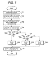
- FIG. 7 An example of process for determining the HIGH shift trigger interval and the lubrication cycle period is shown in Fig. 7. This process is executed by the TMCU 9. Here, the determination of the trigger interval and lubrication period is performed concurrently with the clutch control carried out when the vehicle begins to move.
- the shift lever be in neutral (i.e., that the main gear assembly be in neutral), that the clutch be engaged, and that the engine be idling.
- the clutch is automatically disengaged in order to put the transmission into gear.
- the split gear assembly is shifted into neutral in order to estimate the oil temperature and determine the HIGH shift trigger interval and lubrication cycle period.
- step 701 the clutch is automatically disengaged, and in step 702 the split gear assembly (splitter) is simultaneously shifted into neutral (N).
- step 702 the split gear assembly (splitter) is simultaneously shifted into neutral (N).
- N neutral
- step 703 the main counter shaft rotation rate begins to decrease from Ncidle. Therefore, in step 703, this deceleration in the rate of rotation is calculated, and in step 704, the oil temperature Toil is estimated.
- the TMCU 9 then advances to step 705, in which the estimated oil temperature Toil is compared with the previously set oil temperature Toil1. If Toill ⁇ Toil, the TMCU 9 advances to step 706, and the HIGH shift trigger interval t int is set to t A (here, approximately two hours), and the time t H for a single lubrication cycle is set to a time shorter than time t C (which here is approximately five minutes). If Toil1 ⁇ Toil, the TMCU 9 advances to step 707, and the oil temperature Toil is compared with the set oil temperature Toil2.
- the TMCU 9 advances to step 708, in which the HIGH shift trigger interval t int is set to t B (t B > t A , and here it is approximately four hours), and the period t H for one lubrication cycle is set equal to time t C . If Toil2 ⁇ Toil, the TMCU 9 advances to step 709, in which the HIGH shift trigger interval t int is set to 0, such that the main counter shaft is continuously rotated until the oil temperature Toil reaches Toil2, and lubrication is continuously performed.
- the TMCU 9 advances to step 710, in which main gear assembly shift control and clutch engagement control are performed, and the control process comes to an end.
- this control process allows the longest possible HIGH shift trigger interval and the minimum lubrication cycle period to be obtained based on the actual oil temperature, the lubrication performance and the noise reduction performance may be balanced to the optimal extent, and at the same time high reliability may be maintained.
- the split gear assembly should be shifted into any position other than neutral.
- the specific values for each variable value may also be changed in accordance with given conditions.
- the HIGH shift trigger interval and lubrication cycle period are both determined based on the oil temperature, but it is acceptable if only one of them is determined. In this case, because there is a narrow range of fluctuation in the lubrication time, only the HIGH shift trigger interval may be varied in accordance with the oil temperature.
- the splitter actuator 20 and the TMCU 9 constitute in combination the splitter control of the present invention.
- the vehicle begins moving while there is not sufficient oil circulating in the spline units and the synchromesh units, and the problem of inadequate lubrication occurs to a significant extent.
- the oil level O R is set to just cover the fifth spline 41 and the output shaft spline 70, inherently only a small amount of oil can be scooped up, so it is preferred that sufficient lubrication be provided via the oil pump 35 before the vehicle is driven. This is even more true at low temperatures, in which situation the oil does not circulate easily.
- this transmission 3 has splitter neutral shift prohibition means that prohibits the splitter gear assembly 17 from being shifted into neutral when the engine has just started.
- this means comprises a shift prohibiting program stored beforehand in the TMCU 9. The contents of this program will be describ ed below.
- Fig. 9 shows the contents of the control performed when the engine is stopped, i.e., the splitter N-prohibition control.
- the TMCU 9 determines in step 901 whether or not a vehicle ignition key is in the OFF position, i.e., whether an engine stop instruction has been issued. If the vehicle ignition key is not in the OFF position, the TMCU 9 returns to step 901 and waits for it to be moved to the OFF position, while if it is in the OFF position, the TMCU 9 advances to step 902 and prohibits the execution of control to shift the split gear assembly 17 (splitter) into neutral (N).
- the TMCU 9 shifts it into either HIGH or LOW, while if the split gear assembly 17 is in HIGH or LOW, the TMCU 9 maintains that state. The TMCU 9 then ends control, at which point the ECU 6 stops the engine. As a result, the engine or the vehicle is stopped with the split gear assembly 17 in either HIGH or LOW.
- Fig. 10 shows the control process executed when the engine is started after the control process described above is completed, i.e., splitter N-prohibition maintenance control.
- This control process is begun when the ignition key is turned ON, i.e., as a practical matter, when the engine is started.
- step 1001 the TMCU 9 begins counting using a built-in timer.
- the TMCU 9 then advances to step 1002, in which it compares the counter value C with a preset value C 0 .
- This set value C 0 is defined as the amount of time sufficient to allow oil to be distributed among all of the various units in the transmission that require lubrication, and is determined experimentally. Here, it is ten minutes.
- step 1002 is repeated, while if the counter value C is larger than the C 0 , the TMCU 9 advances to step 1003, in which the control to allow the split gear assembly 17 to be shifted into neutral is permitted.
- the control process ends and normal control shown in Fig. 6 is carried out.
- the splitter is prohibited from being shifted into neutral position until the prescribed time C 0 has elapsed after the engine is started.
- the counter shaft and the oil pump are rotated for at least the period C 0 , and sufficient lubrication is provided inside the transmission.
- Fig. 11 shows a variation of the splitter N-prohibition maintenance control.
- the splitter is kept prohibited from being shifted into neutral until the vehicle speed exceeds a prescribed value after the engine is started.
- the TMCU 9 calculates the vehicle speed V based on the output from the output shaft rotation rate sensor 28, and in step 1102 the TMCU 9 compares the vehicle speed V with a preset value V 0 .
- this set value V 0 is defined as the vehicle speed sufficient to ensure that adequate lubrication is provided to the various units inside the transmission requiring lubrication, and is determined through actual experimentation. Here, it is 50 km/h.
- step 1102 is repeated, while if the sensed value V is larger than the set value V 0 , the TMCU 9 advances to step 1103, in which the control to shift the split gear assembly 17 into neutral is permitted.
- the counter shaft and the oil pump are rotated not only during the warm-up period when the vehicle speed V is zero, but also until the vehicle speed exceeds the set value V 0 , and therefore sufficient lubrication is insured inside the transmission 3 when the engine is started.
- Fig. 12 shows another alternative of the splitter N-prohibition maintenance control process.
- the splitter is prohibited from being shifted into neutral until a prescribed time has elapsed and the vehicle speed exceeds a prescribed value after the engine is started.
- This control process combines the control processes shown in Figs. 10 and 11, or links the two control processes with an AND condition. Specifically, the control process is carried out in following order: steps 1001, 1002, 1101, 1102 and 1003 (1103).
- steps 1001, 1002, 1101, 1102 and 1003 (1103) By this control process, the counter shaft and the oil pump are rotated for at least the period C 0 and until the vehicle speed exceeds the set value V 0 , and therefore sufficient lubrication is provided inside the transmission when the engine is started. It should be noted that these steps may be changed appropriately to create another variation.
- lubrication may be reliably attained when the engine is started, such as during the warm-up period, and failures due to lack of lubrication may be prevented from occurring, even in a range gear assembly having a construction that is not conducive to good lubrication.
- the present invention is not limited to the embodiments described above.
- the present invention can be applied in a transmission which does not have a range gear assembly, because the present invention still insures sufficient lubrication to the split gear assembly and the main gear assembly when the engine is started.
- the clutch may be a fully automatic clutch without a manual clutch function or a normal manual clutch.
Landscapes
- Engineering & Computer Science (AREA)
- General Engineering & Computer Science (AREA)
- Mechanical Engineering (AREA)
- Control Of Transmission Device (AREA)
- General Details Of Gearings (AREA)
- Structure Of Transmissions (AREA)
Applications Claiming Priority (2)
| Application Number | Priority Date | Filing Date | Title |
|---|---|---|---|
| JP36153099A JP4370651B2 (ja) | 1999-12-20 | 1999-12-20 | 車両用多段変速機 |
| JP36153099 | 1999-12-20 |
Publications (3)
| Publication Number | Publication Date |
|---|---|
| EP1111274A2 EP1111274A2 (en) | 2001-06-27 |
| EP1111274A3 EP1111274A3 (en) | 2002-05-22 |
| EP1111274B1 true EP1111274B1 (en) | 2004-03-10 |
Family
ID=18473957
Family Applications (1)
| Application Number | Title | Priority Date | Filing Date |
|---|---|---|---|
| EP00126870A Expired - Lifetime EP1111274B1 (en) | 1999-12-20 | 2000-12-07 | Multiple-gear vehicle transmission |
Country Status (5)
| Country | Link |
|---|---|
| US (1) | US6428447B2 (zh) |
| EP (1) | EP1111274B1 (zh) |
| JP (1) | JP4370651B2 (zh) |
| CN (1) | CN1240565C (zh) |
| DE (1) | DE60008846T2 (zh) |
Families Citing this family (24)
| Publication number | Priority date | Publication date | Assignee | Title |
|---|---|---|---|---|
| DE19915471A1 (de) * | 1999-04-06 | 2000-10-12 | Zahnradfabrik Friedrichshafen | Vorrichtung zur Messung der Getriebeöltemperatur |
| SE521149C2 (sv) * | 2002-02-14 | 2003-10-07 | Volvo Lastvagnar Ab | Smörjanordning för stegväxlad växellåda |
| US7124867B2 (en) | 2002-04-04 | 2006-10-24 | Mizuya Matsufuji | Traveling transmission of working vehicle |
| JP4263459B2 (ja) * | 2002-10-25 | 2009-05-13 | 富士重工業株式会社 | 車両の差動制限制御装置 |
| DE102004055857A1 (de) * | 2004-11-19 | 2006-06-01 | Daimlerchrysler Ag | Verfahren zum Betrieb eines Antriebsstrangs eines Kraftfahrzeugs |
| DE102005013598A1 (de) * | 2005-03-24 | 2006-11-16 | Zf Friedrichshafen Ag | Verfahren zum Betreiben eines Antriebsstrangs eines Kraftfahrzeugs |
| US7597172B1 (en) | 2005-04-22 | 2009-10-06 | Parker-Hannifin Corporation | Gear box for hydraulic energy recovery |
| DE102008014504A1 (de) * | 2008-03-15 | 2009-09-17 | Wabco Gmbh | Getriebesteller |
| EP2286116B1 (en) | 2008-05-09 | 2013-10-02 | Volvo Lastvagnar AB | Method and device for securing lubrication of an automated manual transmission in a vehicle |
| DE102008002294A1 (de) * | 2008-06-09 | 2009-12-10 | Zf Friedrichshafen Ag | Anordnung zur Rasselreduzierung bei einem Getriebe |
| CN102347724A (zh) * | 2010-07-30 | 2012-02-08 | 国网运行有限公司上海超高压管理处 | 带打压动作计数器的电机控制系统 |
| WO2012054015A1 (en) * | 2010-10-18 | 2012-04-26 | Mack Trucks, Inc. | Heavy duty truck transmission with triple overdrive |
| JP5655623B2 (ja) * | 2011-02-23 | 2015-01-21 | いすゞ自動車株式会社 | 副変速機構付き変速機 |
| JP5655624B2 (ja) * | 2011-02-23 | 2015-01-21 | いすゞ自動車株式会社 | 副変速機構付き変速機 |
| JP5842921B2 (ja) * | 2011-09-22 | 2016-01-13 | トヨタ自動車株式会社 | 無段変速機 |
| DE102016206969A1 (de) * | 2016-04-25 | 2017-10-26 | Zf Friedrichshafen Ag | Schaltgetriebe für einen Hybridantrieb, Verfahren zur Steuerung eines solchen Schaltgetriebes, Computerprogrammprodukt, Steuerungs- und/oder Regelungsvorrichtung und Hybridantrieb |
| US10150367B2 (en) | 2016-08-26 | 2018-12-11 | Deere & Company | PTO speed control system for work vehicle |
| US10029562B2 (en) | 2016-08-26 | 2018-07-24 | Deere & Company | Power take-off arrangement for work vehicle |
| EP3559510B1 (en) | 2016-12-22 | 2022-09-07 | Eaton Cummins Automated Transmission Technologies LLC | High efficiency, high output transmission |
| US11105412B2 (en) | 2016-12-22 | 2021-08-31 | Eaton Cummins Automated Transmission Technologies Llc | System, method, and apparatus for managing transmission shutdown operations |
| US10989298B2 (en) | 2016-12-22 | 2021-04-27 | Eaton Cummins Automated Transmission Technologies, Llc | High efficiency, high output transmission |
| CN108571581A (zh) * | 2017-03-13 | 2018-09-25 | 本田技研工业株式会社 | 动力传递装置 |
| CN109058398B (zh) * | 2018-09-28 | 2024-01-02 | 陕西法士特齿轮有限责任公司 | 一种商用车十一档变速器 |
| JP7205511B2 (ja) * | 2020-03-10 | 2023-01-17 | トヨタ自動車株式会社 | 車両用動力伝達装置の制御装置 |
Family Cites Families (5)
| Publication number | Priority date | Publication date | Assignee | Title |
|---|---|---|---|---|
| US5054591A (en) * | 1990-10-11 | 1991-10-08 | Eaton Corporation | Transmission input section control |
| US5335562A (en) | 1992-12-08 | 1994-08-09 | Mastroianni Cesare G | Multi-speed rear wheel drive transmission with reduced in-neutral gear rattle |
| JPH07266907A (ja) | 1994-03-31 | 1995-10-17 | Suzuki Motor Corp | 副変速機のギヤトレーン構造 |
| JP3331766B2 (ja) | 1994-09-21 | 2002-10-07 | 日産自動車株式会社 | トランスファ装置の副変速機 |
| JPH08159258A (ja) * | 1994-12-07 | 1996-06-21 | Nissan Diesel Motor Co Ltd | 車両用多段変速機の変速制御装置 |
-
1999
- 1999-12-20 JP JP36153099A patent/JP4370651B2/ja not_active Expired - Fee Related
-
2000
- 2000-12-07 DE DE60008846T patent/DE60008846T2/de not_active Expired - Lifetime
- 2000-12-07 EP EP00126870A patent/EP1111274B1/en not_active Expired - Lifetime
- 2000-12-14 US US09/737,156 patent/US6428447B2/en not_active Expired - Fee Related
- 2000-12-20 CN CNB00135860XA patent/CN1240565C/zh not_active Expired - Fee Related
Also Published As
| Publication number | Publication date |
|---|---|
| JP4370651B2 (ja) | 2009-11-25 |
| DE60008846T2 (de) | 2005-03-24 |
| CN1300681A (zh) | 2001-06-27 |
| DE60008846D1 (de) | 2004-04-15 |
| US20010004620A1 (en) | 2001-06-21 |
| JP2001173775A (ja) | 2001-06-26 |
| EP1111274A3 (en) | 2002-05-22 |
| EP1111274A2 (en) | 2001-06-27 |
| US6428447B2 (en) | 2002-08-06 |
| CN1240565C (zh) | 2006-02-08 |
Similar Documents
| Publication | Publication Date | Title |
|---|---|---|
| EP1111274B1 (en) | Multiple-gear vehicle transmission | |
| US8113077B2 (en) | Dual clutch transmission | |
| US6217473B1 (en) | Toroidal continuously variable transmission | |
| CN101392803B (zh) | 湿式旋转离合器的阻力矩减小控制装置 | |
| KR100458056B1 (ko) | 자동변속기의오류감지방법 | |
| JPH11230332A (ja) | 機械式変速機の流体補助シフト装置および方法 | |
| US6439082B1 (en) | Multi-stage transmission of vehicle | |
| JP4483613B2 (ja) | 変速制御装置及び方法 | |
| JP4663840B2 (ja) | 自動変速機のエンジンオーバーラン防止装置 | |
| CN100480530C (zh) | 用于车辆自动离合器的控制装置和方法 | |
| US10641393B2 (en) | Automatic transmission | |
| JP4515592B2 (ja) | 車両の自動変速装置 | |
| JP4306132B2 (ja) | 副変速機の切換制御装置及び切換制御方法 | |
| CN113833815B (zh) | 一种amt变速器及新能源汽车 | |
| JP4284820B2 (ja) | 車両の自動変速装置 | |
| JP2002340163A (ja) | 自動変速機の伝動機構 | |
| CN112673198A (zh) | 操作具有两个等效行驶方向的车辆的驱动机构的方法及驱动机构 | |
| JP4426051B2 (ja) | 車両の自動変速装置 | |
| JP4637996B2 (ja) | 車両の自動変速装置 | |
| US11913543B2 (en) | Method and transmission control apparatus for operating a multiple-speed vehicle transmission | |
| JP2002039230A (ja) | 車両用変速機の制御装置 | |
| JP2001343069A (ja) | 車両の自動変速装置 | |
| JP3985647B2 (ja) | 自動変速機の伝動機構 | |
| JP4581178B2 (ja) | 車両の自動変速装置 | |
| JP4505935B2 (ja) | 車両の自動変速装置 |
Legal Events
| Date | Code | Title | Description |
|---|---|---|---|
| PUAI | Public reference made under article 153(3) epc to a published international application that has entered the european phase |
Free format text: ORIGINAL CODE: 0009012 |
|
| AK | Designated contracting states |
Kind code of ref document: A2 Designated state(s): AT BE CH CY DE DK ES FI FR GB GR IE IT LI LU MC NL PT SE TR |
|
| AX | Request for extension of the european patent |
Free format text: AL;LT;LV;MK;RO;SI |
|
| PUAL | Search report despatched |
Free format text: ORIGINAL CODE: 0009013 |
|
| AX | Request for extension of the european patent |
Free format text: AL;LT;LV;MK;RO;SI |
|
| 17P | Request for examination filed |
Effective date: 20021114 |
|
| AKX | Designation fees paid |
Designated state(s): DE FR GB |
|
| REG | Reference to a national code |
Ref country code: GB Ref legal event code: FG4D |
|
| GRAH | Despatch of communication of intention to grant a patent |
Free format text: ORIGINAL CODE: EPIDOS IGRA |
|
| GRAS | Grant fee paid |
Free format text: ORIGINAL CODE: EPIDOSNIGR3 |
|
| GRAA | (expected) grant |
Free format text: ORIGINAL CODE: 0009210 |
|
| AK | Designated contracting states |
Kind code of ref document: B1 Designated state(s): DE FR GB |
|
| REG | Reference to a national code |
Ref country code: IE Ref legal event code: FG4D |
|
| REF | Corresponds to: |
Ref document number: 60008846 Country of ref document: DE Date of ref document: 20040415 Kind code of ref document: P |
|
| ET | Fr: translation filed | ||
| PLBE | No opposition filed within time limit |
Free format text: ORIGINAL CODE: 0009261 |
|
| STAA | Information on the status of an ep patent application or granted ep patent |
Free format text: STATUS: NO OPPOSITION FILED WITHIN TIME LIMIT |
|
| 26N | No opposition filed |
Effective date: 20041213 |
|
| PGFP | Annual fee paid to national office [announced via postgrant information from national office to epo] |
Ref country code: FR Payment date: 20101224 Year of fee payment: 11 |
|
| PGFP | Annual fee paid to national office [announced via postgrant information from national office to epo] |
Ref country code: GB Payment date: 20101201 Year of fee payment: 11 |
|
| PGFP | Annual fee paid to national office [announced via postgrant information from national office to epo] |
Ref country code: DE Payment date: 20101130 Year of fee payment: 11 |
|
| GBPC | Gb: european patent ceased through non-payment of renewal fee |
Effective date: 20111207 |
|
| REG | Reference to a national code |
Ref country code: FR Ref legal event code: ST Effective date: 20120831 |
|
| REG | Reference to a national code |
Ref country code: DE Ref legal event code: R119 Ref document number: 60008846 Country of ref document: DE Effective date: 20120703 |
|
| PG25 | Lapsed in a contracting state [announced via postgrant information from national office to epo] |
Ref country code: DE Free format text: LAPSE BECAUSE OF NON-PAYMENT OF DUE FEES Effective date: 20120703 Ref country code: GB Free format text: LAPSE BECAUSE OF NON-PAYMENT OF DUE FEES Effective date: 20111207 |
|
| PG25 | Lapsed in a contracting state [announced via postgrant information from national office to epo] |
Ref country code: FR Free format text: LAPSE BECAUSE OF NON-PAYMENT OF DUE FEES Effective date: 20120102 |