EP1110857A2 - Dispositif d'équilibrage d'un navire, notamment en roulis - Google Patents
Dispositif d'équilibrage d'un navire, notamment en roulis Download PDFInfo
- Publication number
- EP1110857A2 EP1110857A2 EP00403572A EP00403572A EP1110857A2 EP 1110857 A2 EP1110857 A2 EP 1110857A2 EP 00403572 A EP00403572 A EP 00403572A EP 00403572 A EP00403572 A EP 00403572A EP 1110857 A2 EP1110857 A2 EP 1110857A2
- Authority
- EP
- European Patent Office
- Prior art keywords
- cable
- train
- jaws
- winch
- mobile
- Prior art date
- Legal status (The legal status is an assumption and is not a legal conclusion. Google has not performed a legal analysis and makes no representation as to the accuracy of the status listed.)
- Granted
Links
- 230000000087 stabilizing effect Effects 0.000 title 1
- 230000008878 coupling Effects 0.000 claims description 8
- 238000010168 coupling process Methods 0.000 claims description 8
- 238000005859 coupling reaction Methods 0.000 claims description 8
- 238000005096 rolling process Methods 0.000 claims description 5
- 239000000969 carrier Substances 0.000 abstract description 2
- 238000006073 displacement reaction Methods 0.000 abstract description 2
- 238000004804 winding Methods 0.000 description 5
- 230000000903 blocking effect Effects 0.000 description 3
- 230000015556 catabolic process Effects 0.000 description 2
- 238000012423 maintenance Methods 0.000 description 2
- 239000002184 metal Substances 0.000 description 2
- 229910000831 Steel Inorganic materials 0.000 description 1
- 230000004913 activation Effects 0.000 description 1
- 230000006835 compression Effects 0.000 description 1
- 238000007906 compression Methods 0.000 description 1
- 238000010586 diagram Methods 0.000 description 1
- 230000000694 effects Effects 0.000 description 1
- 230000003100 immobilizing effect Effects 0.000 description 1
- 230000002093 peripheral effect Effects 0.000 description 1
- 238000011084 recovery Methods 0.000 description 1
- 230000000284 resting effect Effects 0.000 description 1
- 239000007787 solid Substances 0.000 description 1
- 239000010959 steel Substances 0.000 description 1
- 230000002747 voluntary effect Effects 0.000 description 1
- 238000005303 weighing Methods 0.000 description 1
- 230000004584 weight gain Effects 0.000 description 1
- 235000019786 weight gain Nutrition 0.000 description 1
Images


Classifications
-
- B—PERFORMING OPERATIONS; TRANSPORTING
- B63—SHIPS OR OTHER WATERBORNE VESSELS; RELATED EQUIPMENT
- B63B—SHIPS OR OTHER WATERBORNE VESSELS; EQUIPMENT FOR SHIPPING
- B63B39/00—Equipment to decrease pitch, roll, or like unwanted vessel movements; Apparatus for indicating vessel attitude
- B63B39/02—Equipment to decrease pitch, roll, or like unwanted vessel movements; Apparatus for indicating vessel attitude to decrease vessel movements by displacement of masses
Definitions
- the invention relates to the balancing of large tonnage vessels, such as aircraft carriers and, in particular, roll balancing, that is to say in gite.
- the presence of the central locking rail means that the rollers have to be designed 19 of restricted diameter, at least in part central, to leave space for the passage of the rail positioning 30. In this way, the mass of the assembly is significantly reduced, as is the effectiveness of the system.
- the object of the invention is therefore to remedy to these disadvantages, by proposing a device balancing of a different ship.
- the adjustment means also have a fixed sheave placed on one side of the device, both mobile sheaves being controlled by a single cylinder and placed on the other side of the device, opposite the sheave fixed, with the motor means and the jack.
- the two mobile sheaves are connected to each other in an elastic manner, the cable passing around these two mobile sheaves, the motor means being made up of a winch placed between these two sheaves mobile and around the drum from which the cable.
- the two strands of the cable is fixed inversely on the winch, around which they wrap and unwind, from this done, alternately and simultaneously.
- the cylinder is preferably a cylinder hydraulic.
- the immobilization means include mainly a pair of jaws, each pair being controlled by one end of the cable, the jaws of each pair being held apart from each other by elastic means to come resting on the side rails, their opening is controlled by cable tension on these two extremities.
- the latter be constituted by lead blocks of a shape almost parallelepiped, mounted on casters rolling on the track.
- the train When, as some requirements for large tonnage vessels, the train must be enclosed in a metal box, the track, on which these moving masses roll, being formed by the lower interior surface of the box, which is installed transversely to to the center line of the ship.
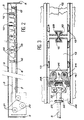
- the system balancing device is installed transversely to the ship, which is symbolized by its side walls 5.
- a metal box 3 is therefore placed transversely on a deck of the ship or ceiling under a bridge.
- the internal surface 7 of the wall lower 8 of box 3 acts as a track for the mobile ground train, which is placed inside the box.
- This train includes several wagons made up each one of a mass of lead 12 mounted on casters 13, which roll on the internal surface 7 of the wall lower 8 of box 3.
- the wagons, thus formed are connected together by a hook hitch 15 placed between each lead mass 12.
- a pair of jaws 16 intended to immobilize the train in moving away and taking support on the side walls of the housing 3.
- the train is towed by a cable 2 which also controls the operation of the two pairs of jaws 16. It is rolled up, in its right part, on a fixed sheave 17 stowed to the carcass of the ship, by example on side wall 5.
- the cable 2 passes through a control assembly, comprising a winch 20 placed between two mobile sheaves 21.
- the winch 20 controls train movements by driving the cable 2 in one direction or the other.
- the two mobile sheaves 21 control the tension of the cable 2, thereby enabling the two pairs of jaws 16.
- Figure 3 shows how the cable 2, a pair of jaws 16 and the train are fixed relative to each other.
- the end of cable 2 is fixed directly to a jaw control part 22 via a shoulder 23 constituting a grip tool grip, in case the cable 2 would be broken.
- Two jaws 24 are mounted pivoting, each around a vertical axis 26, fixed relative to the lead mass 12 at the end of the train.
- a powerful spring 27 maintains permanently the two jaws 24 apart so that each of them rubs against the lateral internal wall 39 of the box.
- the lead weights 12 are attached to each other others with a towing hook 15, which can be advantageously consisting of two heads slightly ball joints 29, each inserted into a cavity coupling 30 of a lead mass 12.
- each jaw 24 can act on the lateral internal surface 28 of the lateral walls of the box, in case these are advantageously each constituted by a profile in form of I, of type IPN, and whose height corresponding to the interior height of the box in which is the train.
- IPN 35 profiles each have two concave parts, one of which corresponds to the interior lateral surface 28. This last one has three parts, a vertical part 28A and two inclined parts 28B at the top and in the bottom of I.
- each jaw 24 has three surfaces, a vertical surface 26A and two inclined surfaces 26B placed on either side of the vertical surface 26A and forming a surface outer corresponding to the lower surface concave 28 of the IPN profile 35.
- each jaw 24 has a maximum yield since an external surface 26 maximum acts on the lateral interior surface 28 of the box.
- each mass of lead 12 is parallelepiped.
- the dimensions of each lead mass 12 correspond to the dimensions of the interior volume of the box 3, delimited mainly by surfaces lower interior 7 and upper interior 34 and through the interior surfaces 28 of the IPN profiles 35.
- a maximum of the interior section of the box 3 is occupied by the lead weights 12, which is a weight gain compared to the system described in patent application FR-2 687 978 and mentioned in the paragraph of the prior art.
- the presence of a central rail, referenced 30, reduced significantly the space available for the masses mobile.
- the fixing of such a rail 30, taking into account the special characteristics of the steel of which it is constituted, poses technological problems, in particular weldability, and its reduced size induced, by the clamping forces, stress levels important.
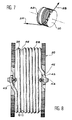
- FIG 4 is shown in detail the cable control assembly 2.
- the last lead weight 12 equipped with a pair of jaws 16 and its support piece 22, as well as the shoulder 23, to which the first cable strand 2A is fixed. It goes around a first mobile mounted 21A sheave in horizontal translation on a first carriage translation 36A, mounted rolling on a floor of the ship.
- the second strand of cable 2B goes into under the train and comes out on the other side of this one. It passes around a second mobile sheave 21B, mounted on a second translation carriage 36B, mounted also rolling on a ship floor. Both translation carriages 36A and 36B are connected between them elastically by a first spring 38A. One of them, in this case the second carriage 38B, is itself elastically connected to the rod mobile 41 of a hydraulic cylinder 40 fixed.
- the two strands 2A and 2B are wound on the winch drum 20A, between its passage on the first mobile sheave 21A and its passage on the second mobile sheave 21B. Whatever position of the 20A winch, in relation to the two sheaves mobile 21A and 21B, this must be established so that cable 2 goes around these two mobile sheaves 21 and 21B, over a quarter of a turn, in opposition to requests due to the fixing of two strands 2A and 2B of cable 2 to the ground train of lead.
- the hydraulic cylinder is controlled by an opening valve due to lack of current, such as a three-way valve 42.
- an opening valve due to lack of current such as a three-way valve 42.
- the relaxation of the two strands 2A and 2B of the cable done by opening the valve due to lack of current, which increases the overall reliability of the system, by compared to a tensioner using an electric jack and therefore requiring the availability of power electric for the relaxation of the two strands 2A and 2B of the cable.
- the tension of cable 2 that is to say, the train is released by activation of the hydraulic cylinder 40 by actuation of valve 42.
- a hydraulic cylinder 40 allows also to reduce the mass of the control means compared to those described in the device of the Patent application 2,687,978, previously described.
- the bearing force generated by the hydraulic cylinder 80 is independent of the position of the movable rod 41 of this last and only depends on the pressure used and the cylinder piston section, which is constant.
- the indication of a pressure gauge 48 makes it possible to monitor directly the tension forces of the two strands of the cable.
- FIG. 4 is also represented, in dashed lines, a second control assembly, identical to that shown in solid lines. he this is the control assembly of a device balancing identical to that previously described and right next to it.
- the balancing device according to the invention must be used in multiple copies. It turns out indeed advantageous to have four or five devices balancing according to the invention at the front and four or five balancing devices aft of the ship. It is pointed out that such a balancing device can move ten masses of lead 12, each weighing about two tonnes. Using ten devices balancing, according to the invention, it is thus possible have two hundred tonnes of balancing on the same ship.
- each of the two strands 2A and 2B of the cable is wound on part of the peripheral surface of the winch 20.
- each end 43 of each strand 2A and 2B is fixed to the winch, for example by means of a bolt 44 and a baffle 45 wedging the end 43 of a strand of the cable.
- the surface of the periphery cylindrical of winch 20 is reserved for winding of each of the two strands 2A and 2B of the cable.
- Figure 8 shows the advantageous presence of two grooves 46 each provided to receive a strand 2A or 2B of the cable.
- the fixation of each ends 43 of the two strands 2A and 2B, at a end of the cylinder constituting the winch 20 one can consider that the throat 46 is common to the two strands 2A and 2B. Indeed, during a rotation of the winch 20, one of the two strands 2A is wound and the other 2B is or, conversely, the amount of length of groove 46 used being substantially constant. So, the unwinding of a 2A strand frees up space for their winding from the other strand 2B of the cable.
- the parallelepiped shape of the masses lead mobile 12 optimizes the volume of the tunnel formed by box 3. Thus, we gain space, and therefore weight, using such moving masses. The effectiveness of the device is therefore increased.
- each pair of jaws 22 constitutes security, in particular in the case of rupture of one of the two strands of cable 2, during a maneuvering the moving train.
- lead masses 12 mobile equipped with four casters 13, allows them to move on the wings of standard profiles 35, constituting the lateral parts of the box.
- towing hooks 15 of ball type or similar allows some freedom movement between the masses of lead 12, in particular in angle.
Landscapes
- Chemical & Material Sciences (AREA)
- Engineering & Computer Science (AREA)
- Combustion & Propulsion (AREA)
- Mechanical Engineering (AREA)
- Ocean & Marine Engineering (AREA)
- Laying Of Electric Cables Or Lines Outside (AREA)
- Ropes Or Cables (AREA)
Abstract
Description
- un train de masse mobile roulant sur une piste ;
- des moyens d'immobilisation du train ;
- un câble de traction du train et de commande des moyens d'immobilisation ;
- un moyen moteur pour actionner le câble ; et
- des moyens de réglage de la tension du câble en vue de commander les moyens d'immobilisation, comprenant deux réas mobiles pour régler la tension du câble.
- figure 1, en vue cavalière, un dispositif d'équilibrage selon l'art antérieur ;
- figure 2, une vue globale, en coupe, du dispositif d'équilibrage selon l'invention ;
- figure 3, en vue de dessus, en coupe, une paire de mâchoires utilisée dans les moyens d'immobilisation du train du dispositif d'équilibrage selon l'invention ;
- figure 4, une vue détaillée des moyens moteurs et de réglage de la tension du câble dans le dispositif selon l'invention ;
- figure 5, en vue de côté, les mâchoires représentées à la figure 4 ;
- figure 6, en coupe, vu de côté, une des masses mobiles du train d'un dispositif d'équilibrage selon l'invention ;
- figure 7, un schéma de l'enroulement du câble sur le treuil dont le dispositif d'équilibrage selon l'invention ;
- figure 8, le treuil du dispositif d'équilibrage selon l'invention.
Claims (12)
- Dispositif d'équilibrage de navires, notamment en roulis, comprenant :caractérisé en ce que les moyens de réglage comprennent un réa fixe (17), placé d'un côté du dispositif et deux réas mobiles (21A, 21B) étant commandés par un seul vérin (40) et étant placés tous deux du côté opposé au réa fixe (17), avec les moyens moteurs et le vérin (40).un train de masses mobiles roulant sur une piste ;des moyens d'immobilisation du train ;un câble (2) de traction du train et de commande des moyens d'immobilisation ;un moyen moteur pour actionner le câble (2) ; etdes moyens de réglage de la tension du câble (2) en vue de commander les moyens d'immobilisation et comprenant deux réas mobiles pour régler la tension du câble (2),
- Dispositif selon la revendication 1, caractérisé en ce que les réas mobiles (21A et 21B) sont reliés entre eux, de façon élastique, le câble (2) passant autour des deux réas mobiles (21A, 21B).
- Dispositif selon la revendication 2, caractérisé en ce que le premier réa mobile (21B) est relié élastiquement au vérin (40).
- Dispositif selon la revendication 1, caractérisé en ce que les moyens moteurs sont constitués d'un treuil (20, 20A, 20B), placé entre les deux réas mobiles (21A, 21B).
- Dispositif selon la revendication 1, caractérisé en ce que le vérin (40) est un vérin hydraulique.
- Dispositif selon la revendication 5, caractérisé en ce que le vérin hydraulique (40) est commandé par une électrovanne à manque de courant (42).
- Dispositif selon la revendication 1, dans lequel les moyens de guidage d'un train sont deux profilés latéraux (35), caractérisé en ce que les moyens d'immobilisation comprennent une paire de mâchoires (24), à chaque extrémité du train, les mâchoires (24) étant maintenues écartées contre la surface interne des rails latéraux et reliés à une extrémité du câble (2) dont une tension provoque un rapprochement des deux mâchoires (24) d'une paire de mâchoire (16).
- Dispositif selon la revendication 7, caractérisé en ce que les deux rails étant des profilés en I standardisé, du type « IPN » (35), ayant au moins une partie concave interne constituée d'une surface interne verticale (28A) et de deux surfaces internes inclinées (28B), caractérisé en ce que les mâchoires (24) possèdent trois surfaces de frottement, une surface de frottement verticale (26A) et deux surfaces de frottement inclinées (26B), s'appuyant respectivement sur les trois surfaces internes (28A, 28B) du rail latéral (35) correspondant.
- Dispositif selon la revendication 1, caractérisé en ce que les masses mobiles sont constituées par des masses de plomb (12) d'une forme quasi parallélépipédique et montées sur des roulettes (13) roulant sur la piste.
- Dispositif selon la revendication 1, caractérisé en ce que la piste est constituée par la surface interne inférieure (7) d'un caisson (3) métallique et installé transversalement par rapport à l'axe du navire.
- Dispositif selon la revendication 2, caractérisé en ce que les deux brins (2A, 2B) du câble (2) sont fixés sur le treuil (20, 20A, 20B) de façon inversée, et autour duquel il s'enroulent et se déroulent, de ce fait, en alternance et simultanément.
- Dispositif selon la revendication 1, caractérisé en ce que chaque treuil (20A, 20B) à des moyens d'accouplement temporaires (48) avec le treuil (20B, 20A) d'un dispositif adjacent, pour que l'un puisse entraíner l'autre, en cas de panne de l'un des deux.
Applications Claiming Priority (2)
| Application Number | Priority Date | Filing Date | Title |
|---|---|---|---|
| FR9916066A FR2802504B1 (fr) | 1999-12-20 | 1999-12-20 | Dispositif ameliore d'equilibrage d'un navire notamment en roulis |
| FR9916066 | 1999-12-20 |
Publications (3)
| Publication Number | Publication Date |
|---|---|
| EP1110857A2 true EP1110857A2 (fr) | 2001-06-27 |
| EP1110857A3 EP1110857A3 (fr) | 2001-08-08 |
| EP1110857B1 EP1110857B1 (fr) | 2005-10-26 |
Family
ID=9553478
Family Applications (1)
| Application Number | Title | Priority Date | Filing Date |
|---|---|---|---|
| EP00403572A Expired - Lifetime EP1110857B1 (fr) | 1999-12-20 | 2000-12-18 | Dispositif d'équilibrage d'un navire, notamment en roulis |
Country Status (5)
| Country | Link |
|---|---|
| US (1) | US6349660B2 (fr) |
| EP (1) | EP1110857B1 (fr) |
| JP (1) | JP4718680B2 (fr) |
| DE (1) | DE60023432T2 (fr) |
| FR (1) | FR2802504B1 (fr) |
Cited By (3)
| Publication number | Priority date | Publication date | Assignee | Title |
|---|---|---|---|---|
| WO2009026964A1 (fr) * | 2007-08-30 | 2009-03-05 | Speed 4 Sail S.A. | Ballast mobile pour bateau à voile et navire |
| WO2011028102A3 (fr) * | 2009-09-04 | 2011-11-03 | Itrec B.V. | Installation d'éolienne en mer |
| US9038554B2 (en) | 2011-04-20 | 2015-05-26 | Vincent de Troz | Mobile ballast device |
Families Citing this family (12)
| Publication number | Priority date | Publication date | Assignee | Title |
|---|---|---|---|---|
| FR2831135B1 (fr) | 2001-10-18 | 2004-01-23 | Technicatome | Dispositif d'equilibrage de navires de faible tonnage |
| US20070084394A1 (en) * | 2005-10-19 | 2007-04-19 | Peter Gudmundson | Power generation in watercraft |
| CN101918271B (zh) * | 2007-10-11 | 2013-09-11 | 伊特雷科公司 | 带横摇阻尼机构的船 |
| WO2009120062A2 (fr) * | 2008-03-26 | 2009-10-01 | Itrec B.V. | Système et procédé de compensation de pilonnement |
| CN102079364B (zh) * | 2009-11-27 | 2013-04-10 | 三一电气有限责任公司 | 风机安装船及其重心调节装置 |
| US9150291B2 (en) * | 2013-01-23 | 2015-10-06 | Elliott B. Dollar | Weight distribution device and method for modifying wake |
| US9926052B2 (en) | 2015-12-30 | 2018-03-27 | Abb Schweiz Ag | Control mechanism for transformer in-situ inspection device |
| KR101847739B1 (ko) | 2016-10-17 | 2018-04-10 | (주)한국해사기술 | 유압시스템의 이배속 운송장치 |
| KR101847737B1 (ko) | 2016-10-17 | 2018-04-10 | (주)한국해사기술 | 피스톤 로드의 좌굴 방지 장치 및 방법 |
| WO2018125229A1 (fr) * | 2016-12-30 | 2018-07-05 | Abb Schweiz Ag | Mécanisme de commande pour dispositif d'inspection in situ de transformateur |
| CN111216845A (zh) * | 2020-02-14 | 2020-06-02 | 武汉理工大学 | 双洞单向通航隧洞船舶循环曳引系统 |
| CN114476996A (zh) * | 2022-03-09 | 2022-05-13 | 上海振华重工(集团)股份有限公司 | 一种用于摩擦绞车的张紧装置 |
Citations (1)
| Publication number | Priority date | Publication date | Assignee | Title |
|---|---|---|---|---|
| FR2687978A1 (fr) | 1992-02-27 | 1993-09-03 | Technicatome | Dispositif d'equilibrage de navire notamment en roulis. |
Family Cites Families (14)
| Publication number | Priority date | Publication date | Assignee | Title |
|---|---|---|---|---|
| DE349886C (de) * | 1922-03-09 | Naamlooze Vennootschap Werf Co | Vorrichtung zur Sperrung eines fahrbaren Ballastgewichtes auf Schiffen oder Pontons beim Reissen des Zugseiles oder sonstigen Stoerungen | |
| DE324970C (de) * | 1915-08-12 | 1920-09-07 | Hamburg Und Stettin Act Ges | Verfahren zum Daempfen schwingender Bewegungen von Koerpern, insbesondere der Rollbewegungen von Schiffen |
| US1853069A (en) * | 1931-06-15 | 1932-04-12 | Minorsky Nicolai | Stabilizing apparatus |
| US3397664A (en) * | 1966-09-16 | 1968-08-20 | Hydronautics | Vessel stabilizer |
| US3426718A (en) * | 1968-02-27 | 1969-02-11 | Hydronautics | Vessel stabilizer |
| DE1945548A1 (de) * | 1969-09-09 | 1971-03-11 | Siemens Ag | Schiff mit Stabilisierungsanlage |
| US3934534A (en) * | 1972-07-19 | 1976-01-27 | Larsh Everett P | Marine vessel roll stabilizer apparatus |
| FR2322778A1 (fr) * | 1975-09-05 | 1977-04-01 | Southwestern Ind Inc | Stabilisateur de roulis pour bateau |
| JPH06183394A (ja) * | 1992-12-18 | 1994-07-05 | Ishikawajima Harima Heavy Ind Co Ltd | 海洋構造物の減揺装置 |
| US5713163A (en) * | 1995-01-19 | 1998-02-03 | Ishikawajima-Harima Heavy Industries Co. Ltd. | Vibration damping apparatus |
| JPH0953681A (ja) * | 1995-08-18 | 1997-02-25 | Univ Kyoto | 重力作用型動吸振器およびその振動周期調整法 |
| JP3874835B2 (ja) * | 1996-03-25 | 2007-01-31 | 株式会社トキメック | 減揺装置 |
| US6019056A (en) * | 1996-10-23 | 2000-02-01 | Tokimec Inc. | Anti-rolling apparatus |
| JPH10119886A (ja) * | 1996-10-23 | 1998-05-12 | Tokimec Inc | 減揺装置 |
-
1999
- 1999-12-20 FR FR9916066A patent/FR2802504B1/fr not_active Expired - Fee Related
-
2000
- 2000-12-18 DE DE60023432T patent/DE60023432T2/de not_active Expired - Lifetime
- 2000-12-18 EP EP00403572A patent/EP1110857B1/fr not_active Expired - Lifetime
- 2000-12-18 US US09/739,196 patent/US6349660B2/en not_active Expired - Lifetime
- 2000-12-19 JP JP2000385368A patent/JP4718680B2/ja not_active Expired - Fee Related
Patent Citations (1)
| Publication number | Priority date | Publication date | Assignee | Title |
|---|---|---|---|---|
| FR2687978A1 (fr) | 1992-02-27 | 1993-09-03 | Technicatome | Dispositif d'equilibrage de navire notamment en roulis. |
Cited By (4)
| Publication number | Priority date | Publication date | Assignee | Title |
|---|---|---|---|---|
| WO2009026964A1 (fr) * | 2007-08-30 | 2009-03-05 | Speed 4 Sail S.A. | Ballast mobile pour bateau à voile et navire |
| WO2011028102A3 (fr) * | 2009-09-04 | 2011-11-03 | Itrec B.V. | Installation d'éolienne en mer |
| US8701579B2 (en) | 2009-09-04 | 2014-04-22 | Itrec B.V. | Offshore wind turbine installation |
| US9038554B2 (en) | 2011-04-20 | 2015-05-26 | Vincent de Troz | Mobile ballast device |
Also Published As
| Publication number | Publication date |
|---|---|
| US20010003963A1 (en) | 2001-06-21 |
| DE60023432T2 (de) | 2006-07-27 |
| JP4718680B2 (ja) | 2011-07-06 |
| FR2802504A1 (fr) | 2001-06-22 |
| US6349660B2 (en) | 2002-02-26 |
| DE60023432D1 (de) | 2005-12-01 |
| FR2802504B1 (fr) | 2002-03-01 |
| EP1110857B1 (fr) | 2005-10-26 |
| JP2001206287A (ja) | 2001-07-31 |
| EP1110857A3 (fr) | 2001-08-08 |
Similar Documents
| Publication | Publication Date | Title |
|---|---|---|
| EP1110857B1 (fr) | Dispositif d'équilibrage d'un navire, notamment en roulis | |
| EP1228330B1 (fr) | Systeme de pinces pour maintenir une conduite en tension, et support flottant en comprenant | |
| CA2470266A1 (fr) | Systeme de levage et de stabilisation d'un support de charge suspendu | |
| EP1351878B1 (fr) | Dispositif de freinage d'urgence pour un vehicule tracte ou assure par cables et vehicule muni d'un tel dispositif | |
| EP2089302B1 (fr) | Sabot de calage d'une roue et installation de calage motorisee | |
| WO1996000359A1 (fr) | Dispositif de pose de conduites flexibles a partir d'un support flottant | |
| EP0292413B1 (fr) | Dispositif compensateur de charge pour un engin de manutention et procédé pour la mise en oeuvre d'une telle compensation | |
| EP0020257A1 (fr) | Dispositif pour la pose en J d'une canalisation sous-marine | |
| CA2124103C (fr) | Procede et dispositif de levage de manutention de charge en mer | |
| EP1304289B1 (fr) | Dispositif d'équilibrage des navires de faible tonnage | |
| FR2484948A1 (fr) | Dispositif pour manutentionner a partir d'un bateau une charge immergee accrochee a l'extremite d'un cable | |
| EP0003326B1 (fr) | Dispositif automatique de vissage et de manutention de goujons | |
| EP0114146B1 (fr) | Machine de forage polyvalente dotée de moyens de remontée rapide du train de tiges | |
| EP0589772B1 (fr) | Appareillage d'essai de sol du type à plaque et véhicule équipé d'un tel appareillage | |
| FR2939398A1 (fr) | Dispositif pour securiser la manutention d'une charge roulante sur une plate-forme telle que le pont d'un navire soumis a une mer agitee. | |
| EP0001370A1 (fr) | Unité mobile avec appareils de levage et de démontage indépendants et amovibles, en vue du dépannage et de l'entretien sur place de véhicules routiers | |
| EP0005089B1 (fr) | Véhicule pour le transport d'autres véhicules | |
| WO2013139689A1 (fr) | Systeme de traction pour un vehicule et procede pour assurer une traction securisee d'un vehicule sur un sol | |
| FR2543937A1 (fr) | Dispositif de levage et de transport sur des voies ferrees | |
| FR2522081A1 (fr) | Verin moufle a double effet utilisable notamment pour commander les mouvements de fermeture et d'ouverture d'une porte coulissante ou basculante | |
| FR2526743A1 (fr) | Dispositif permettant d'immobiliser ou de faire progresser un wagon sur une voie ferree | |
| FR3048239A1 (fr) | Treuil a enroulement facilite | |
| FR3055588A1 (fr) | Vehicule fer/route pour la mise en place de catenaire | |
| EP1015375B1 (fr) | Perfectionnement aux treuils motorises pour l'amarrage d'engins flottants du genre navires, plateformes, etc. | |
| WO2021249911A1 (fr) | Systeme de manutention d'une ligne d'arbre d'un navire |
Legal Events
| Date | Code | Title | Description |
|---|---|---|---|
| PUAI | Public reference made under article 153(3) epc to a published international application that has entered the european phase |
Free format text: ORIGINAL CODE: 0009012 |
|
| PUAL | Search report despatched |
Free format text: ORIGINAL CODE: 0009013 |
|
| AK | Designated contracting states |
Kind code of ref document: A2 Designated state(s): DE GB IT |
|
| AX | Request for extension of the european patent |
Free format text: AL;LT;LV;MK;RO;SI |
|
| AK | Designated contracting states |
Kind code of ref document: A3 Designated state(s): AT BE CH CY DE DK ES FI FR GB GR IE IT LI LU MC NL PT SE TR |
|
| AX | Request for extension of the european patent |
Free format text: AL;LT;LV;MK;RO;SI |
|
| 17P | Request for examination filed |
Effective date: 20020202 |
|
| AKX | Designation fees paid |
Free format text: DE GB IT |
|
| GRAP | Despatch of communication of intention to grant a patent |
Free format text: ORIGINAL CODE: EPIDOSNIGR1 |
|
| GRAS | Grant fee paid |
Free format text: ORIGINAL CODE: EPIDOSNIGR3 |
|
| GRAA | (expected) grant |
Free format text: ORIGINAL CODE: 0009210 |
|
| AK | Designated contracting states |
Kind code of ref document: B1 Designated state(s): DE GB IT |
|
| REG | Reference to a national code |
Ref country code: GB Ref legal event code: FG4D Free format text: NOT ENGLISH |
|
| REF | Corresponds to: |
Ref document number: 60023432 Country of ref document: DE Date of ref document: 20051201 Kind code of ref document: P |
|
| GBT | Gb: translation of ep patent filed (gb section 77(6)(a)/1977) |
Effective date: 20060125 |
|
| PLBE | No opposition filed within time limit |
Free format text: ORIGINAL CODE: 0009261 |
|
| STAA | Information on the status of an ep patent application or granted ep patent |
Free format text: STATUS: NO OPPOSITION FILED WITHIN TIME LIMIT |
|
| 26N | No opposition filed |
Effective date: 20060727 |
|
| PGFP | Annual fee paid to national office [announced via postgrant information from national office to epo] |
Ref country code: IT Payment date: 20151215 Year of fee payment: 16 Ref country code: GB Payment date: 20151218 Year of fee payment: 16 Ref country code: DE Payment date: 20151209 Year of fee payment: 16 |
|
| REG | Reference to a national code |
Ref country code: DE Ref legal event code: R119 Ref document number: 60023432 Country of ref document: DE |
|
| GBPC | Gb: european patent ceased through non-payment of renewal fee |
Effective date: 20161218 |
|
| PG25 | Lapsed in a contracting state [announced via postgrant information from national office to epo] |
Ref country code: IT Free format text: LAPSE BECAUSE OF NON-PAYMENT OF DUE FEES Effective date: 20161218 |
|
| PG25 | Lapsed in a contracting state [announced via postgrant information from national office to epo] |
Ref country code: GB Free format text: LAPSE BECAUSE OF NON-PAYMENT OF DUE FEES Effective date: 20161218 Ref country code: DE Free format text: LAPSE BECAUSE OF NON-PAYMENT OF DUE FEES Effective date: 20170701 |