EP1110744A1 - Vorrichtung und Verfahren zur Motorsteuerung - Google Patents
Vorrichtung und Verfahren zur Motorsteuerung Download PDFInfo
- Publication number
- EP1110744A1 EP1110744A1 EP00311536A EP00311536A EP1110744A1 EP 1110744 A1 EP1110744 A1 EP 1110744A1 EP 00311536 A EP00311536 A EP 00311536A EP 00311536 A EP00311536 A EP 00311536A EP 1110744 A1 EP1110744 A1 EP 1110744A1
- Authority
- EP
- European Patent Office
- Prior art keywords
- motor
- pulse
- velocity
- edges
- encoder
- Prior art date
- Legal status (The legal status is an assumption and is not a legal conclusion. Google has not performed a legal analysis and makes no representation as to the accuracy of the status listed.)
- Granted
Links
Images


Classifications
-
- B—PERFORMING OPERATIONS; TRANSPORTING
- B41—PRINTING; LINING MACHINES; TYPEWRITERS; STAMPS
- B41J—TYPEWRITERS; SELECTIVE PRINTING MECHANISMS, i.e. MECHANISMS PRINTING OTHERWISE THAN FROM A FORME; CORRECTION OF TYPOGRAPHICAL ERRORS
- B41J19/00—Character- or line-spacing mechanisms
- B41J19/18—Character-spacing or back-spacing mechanisms; Carriage return or release devices therefor
- B41J19/20—Positive-feed character-spacing mechanisms
-
- B—PERFORMING OPERATIONS; TRANSPORTING
- B41—PRINTING; LINING MACHINES; TYPEWRITERS; STAMPS
- B41J—TYPEWRITERS; SELECTIVE PRINTING MECHANISMS, i.e. MECHANISMS PRINTING OTHERWISE THAN FROM A FORME; CORRECTION OF TYPOGRAPHICAL ERRORS
- B41J11/00—Devices or arrangements of selective printing mechanisms, e.g. ink-jet printers or thermal printers, for supporting or handling copy material in sheet or web form
- B41J11/36—Blanking or long feeds; Feeding to a particular line, e.g. by rotation of platen or feed roller
- B41J11/42—Controlling printing material conveyance for accurate alignment of the printing material with the printhead; Print registering
-
- B—PERFORMING OPERATIONS; TRANSPORTING
- B41—PRINTING; LINING MACHINES; TYPEWRITERS; STAMPS
- B41J—TYPEWRITERS; SELECTIVE PRINTING MECHANISMS, i.e. MECHANISMS PRINTING OTHERWISE THAN FROM A FORME; CORRECTION OF TYPOGRAPHICAL ERRORS
- B41J19/00—Character- or line-spacing mechanisms
- B41J19/18—Character-spacing or back-spacing mechanisms; Carriage return or release devices therefor
- B41J19/20—Positive-feed character-spacing mechanisms
- B41J19/202—Drive control means for carriage movement
- B41J19/205—Position or speed detectors therefor
- B41J19/207—Encoding along a bar
-
- H—ELECTRICITY
- H02—GENERATION; CONVERSION OR DISTRIBUTION OF ELECTRIC POWER
- H02P—CONTROL OR REGULATION OF ELECTRIC MOTORS, ELECTRIC GENERATORS OR DYNAMO-ELECTRIC CONVERTERS; CONTROLLING TRANSFORMERS, REACTORS OR CHOKE COILS
- H02P23/00—Arrangements or methods for the control of AC motors characterised by a control method other than vector control
- H02P23/16—Controlling the angular speed of one shaft
-
- H—ELECTRICITY
- H02—GENERATION; CONVERSION OR DISTRIBUTION OF ELECTRIC POWER
- H02P—CONTROL OR REGULATION OF ELECTRIC MOTORS, ELECTRIC GENERATORS OR DYNAMO-ELECTRIC CONVERTERS; CONTROLLING TRANSFORMERS, REACTORS OR CHOKE COILS
- H02P7/00—Arrangements for regulating or controlling the speed or torque of electric DC motors
- H02P7/06—Arrangements for regulating or controlling the speed or torque of electric DC motors for regulating or controlling an individual dc dynamo-electric motor by varying field or armature current
- H02P7/18—Arrangements for regulating or controlling the speed or torque of electric DC motors for regulating or controlling an individual dc dynamo-electric motor by varying field or armature current by master control with auxiliary power
- H02P7/24—Arrangements for regulating or controlling the speed or torque of electric DC motors for regulating or controlling an individual dc dynamo-electric motor by varying field or armature current by master control with auxiliary power using discharge tubes or semiconductor devices
- H02P7/28—Arrangements for regulating or controlling the speed or torque of electric DC motors for regulating or controlling an individual dc dynamo-electric motor by varying field or armature current by master control with auxiliary power using discharge tubes or semiconductor devices using semiconductor devices
- H02P7/2805—Arrangements for regulating or controlling the speed or torque of electric DC motors for regulating or controlling an individual dc dynamo-electric motor by varying field or armature current by master control with auxiliary power using discharge tubes or semiconductor devices using semiconductor devices whereby the speed is regulated by measuring the motor speed and comparing it with a given physical value
Definitions
- This invention relates to a motor control apparatus and a motor control method, and particularly, to a motor control apparatus and motor control method of controlling a motor by selectively employing timings of the rising and falling of pulse signals from an encoder which are used in serial printer to control a carriage motor driving a carriage or a paper feeding motor practicing a sheet feeding task, so as to detect a motor velocity.
- the present invention is also directed to a record medium that stores computer programs to execute such a motor control method.
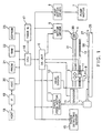
- Fig. 1 is a block diagram that shows general configuration of an ink jet printer.
- the ink jet printer shown in Fig. 1 includes a paper feed motor (hereinafter also called a PF motor) 1 that feeds paper; a paper feed motor driver 2 that drives the paper feed motor 1; a carriage 3 that supports a head 9 fixed thereto to supply ink onto printing paper 50 and is driven to move in parallel to the printing paper 50 and vertically of the paper feeding direction; a carriage motor (hereinafter also called a CRmotor) 4 that drives the carriage 3; a CR motor driver 5 that drives the carriage motor 4; a DC unit 6 that outputs a D.C.
- a paper feed motor hereinafter also called a PF motor
- a paper feed motor driver 2 that drives the paper feed motor 1
- a carriage 3 that supports a head 9 fixed thereto to supply ink onto printing paper 50 and is driven to move in parallel to the printing paper 50 and vertically of the paper feeding direction
- a carriage motor hereinafter also called a CRmotor 4 that drives the carriage 3
- a CR motor driver 5 that drives the carriage
- a pump motor 7 that controls the draft of ink for the purpose of preventing clogging of the head 9
- a pump motor driver 8 that drives the pump motor 7
- a head driver 10 that drives and controls the head 9
- a linear encoder 11 fixed to the carriage 3
- a linear encoder coding plate 12 having slits in predetermined intervals
- a rotary encoder 13 for the PF motor 1
- a paper detecting sensor 15 that detects the terminal position of each sheet of paper under printing
- a CPU 16 that controls the whole printer
- a timer IC 17 that periodically generates interruption signals to the CPU 16
- an interface portion (hereinafter also called IF) 19 that exchanges data with a host computer 18
- an ASIC 20 that controls the character resolution, driving waveform of the head 9, and so on, in accordance with character information sent from the host computer 18 through the IF 19
- a PROM 21, a RAM 22 and an EEPROM 23 that are used as an operation area of the ASIC 20 and the CPU 16 and
- the DC unit 6 controls and drives the paper feed motor driver 2 and the CR motor driver 5 in response to a control instruction sent from the CPU 16 and outputs of the encoders 11, 13. Both the paper feed motor 1 and the CR motor 4 are DC motors.
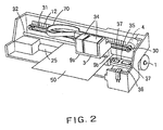
- Fig. 2 is a perspective view that illustrates configuration around the carriage 3 of the ink jet printer.
- the carriage 3 is connected to the carriage motor 4 by the timing belt 31 via the pulley 30, and driven to move in parallel with the platen 25 under guidance of a guide member 32.
- the carriage 3 has the recording head 9 projecting from its surface opposed to the printing paper and having a row of nozzles for releasing black ink and a row of nozzles for releasing color ink. These nozzles are supplied with ink from the ink cartridge 34 and release drops of ink onto the printing paper to print characters and images.
- a capping device 35 for shutting nozzle openings of the recording head 9 when printing is not executed, and a pump unit 36 having the pump motor 7 shown in Fig. 1.
- the carriage 3 moves from the print area to the non-print area, it contacts a lever, not shown, and the capping device 35 moves upward to close the head 9.
- the pump unit 36 When any of the nozzle openings of the head 9 is clogged, or ink is forcibly released from the head 9 just after replacement of the cartridge 34, the pump unit 36 is activated while closing the head 9, and a negative pressure from the pump unit 36 is used to suck out ink from the nozzle openings. As a result, dust and paper powder are washed out from around the nozzle openings, and bubbles in the head 9, if any, are discharged together with the ink to the cap 37.
- Fig. 3 is a diagram schematically illustrating configuration of the linear encoder 11 attached to the carriage 3.
- the encoder 11 shown in Gig. 3 includes a light emitting diode lla, collimator lens 11b and detector/processor 11c.
- the detector/processor 11c has a plurality of (four) photo diodes lid, signal processing circuit lie, and two comparators 11 fA , 11 fB .
- the coding plate 12 has slits in predetermined intervals (for example, in intervals of 1/180 inch).
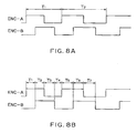
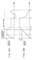
- Figs. 4A and 4B are timing charts showing waveforms of two output signals from the encoder 11 during normal rotation of the CR motor and during its reverse rotation.
- the pulse ENC-A and the pulse ENC-B are different in phase by 90 degrees.
- the encoder 4 is so configured that the pulse ENC-A is forward in phase by 90 degrees relative to the pulse ENC-B as shown in Fig. 4A when the CR motor 4 rotates in the normal direction, i.e., when the carriage 3 is moving in its main scanning direction whereas the pulse ENC-A is behind in phase by 90 degrees relative to the pulse ENC-B as shown in Fig. 4B when the CR motor 4 rotates in the reverse direction.
- one period T of these pulses corresponds to each interval of the slits of the coding plate 12 (for example, 1/180 inch), and it is equal to the time required for the carriage 3 to move from a slit to another.
- the rotary encoder 13 for the PF motor 1 has the same configuration as the linear encoder 11 except that the former is a rotatable disc that rotates in response to rotation of the PF motor 1, and the rotary encoder 13 also outputs two output pulses ENC-A, ENC-B.
- slit interval of a plurality of slits provided on a coding plate of the encoder 13 for the PF motor 1 is 1/180 inch, and paper is fed by 1/1440 inch when the PF motor rotates by each slit interval.
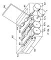
- Fig. 5 is a perspective view showing a part related to paper feeding and paper detection.
- a sheet of printing paper 50 inserted into a paper feed inlet 61 of a printer 60 is conveyed into the printer 60 by a paper feed roller 64 driven by a paper feed motor 63.
- the forward end of the printing paper 50 conveyed into the printer 60 is detected by an optical paper detecting sensor 15, for example.
- the paper 50 whose forward end is detected by the paper detecting sensor 15 is transported by a paper feed roller 65 driven by the PF motor 1 and a free roller 66.
- ink is released from the recording head (not shown) fixed to the carriage 3 which moves along the carriage guide member 32 to print something on the printing paper 50.
- the paper detecting sensor 15 detects the terminal end of the printing paper 50 currently under printing.
- the printing paper 50 after printing is discharged outside from a paper outlet 62 by a discharge roller 68 driven by a gear 67C, which is driven by the PF motor 1 via gears 67A, 67B, and a free roller 69.
- Fig. 6 is a perspective view illustrating details of parts associated to paper feeding in a printer, where a paper feeding roller 65 has a rotation axis coupled to a rotary encoder 13.
- the paper feeding roller 65 is provided on and about a smap shaft 83 or a rotation axis of a large gear 67a engaged with a small gear 87 driven by a PF motor 1 while the follower roller 66 is provided in a holder 89 at its paper evacuating end in the context of a paper feeding direction, where the printing paper 50 from a paper supply source is pressed vertically.
- the PF motor 1 is fitted in and secured to a frame 86 in the printer 60 by a screw 85, and the rotary encoder 13 is placed in a specified position around the large gear 67a while a character board 14 for the rotary encoder is connected to the smap shaft 83 or the rotation axis of the large gear 67a.
- a paper evacuating gear 68 which is rotated by the PF motor 1 via a group of gears, the small gear 87, the large gear 67a, a medium gear 67b, a small gear 88, and a paper evacuating gear 67c, and a toothed roller 69 or a follower roller cooperatively presses and holds the printing paper 50 between them to further feed the printing paper 50 until it is evacuated from the paper outlet 62 to the outside of the printer.
- a carriage 3 moves laterally in a space defined above the platen 84 along a guide member 32, and simultaneously, ink is injected from a recording head (not shown) fixed to the carriage 3 to print characters in the printing paper.
- DC unit 6 is a prior art DC motor control apparatus used to control a carriage (CR) motor 4 for such an ink jet printer as mentioned above, and additionally, a control method by the DC unit 6 will also be explained.
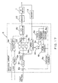
- Fig. 7 is a block diagram showing an arrangement of the DC unit 6 serving as the DC motor control apparatus while Fig. 8 is a timing chart illustrating conditions of encoder pulse edge detection in a speed calculator 6d of the prior art DC unit 6, and Figs. 9A and 9B are graphs illustrating time-varying motor current and motor speed of the CR motor 4 under control by the DC unit 6.
- the DC unit 6 shown in Fig. 7 includes a position operator 6a, a subtracter 6b, a target speed operator 6c, a speed operator 6d, a subtracter 6e, a proportional element 6f, an integral element 6g, a differential element 6h, an adder 6i, a D/A converter 6j, a timer 6k, and an acceleration controller 6m.
- the position operator 6a detects rising edges and tail edges of the output pulses ENC-A and ENC-B of the encoder 11, then counts the number of edges detected, and operates the position of the carriage 3 from the counted value. This counting adds "+1" when one edge is detected while the CR motor 4 rotates in the normal direction, and adds "-1" when one edge is detected while the CR motor 4 rotates in the reverse direction.
- Period of pulses ENC-A and period of pulses ENC-B are equal to the slit interval of the coding plate 12, and the pulses ENC-A and ENC-B are different in phase by 90 degrees. Therefore, the count value "1" of that counting corresponds to 1/4 of the slit interval of the coding plate 12.
- the subtracter 6b operates positional difference between the target position sent from the CPU 16 and the actual position of the carriage 3 obtained by the position operator 6a.
- the target speed calculator 6c computes a target velocity of the carriage 3 by referring to a positional deviation produced by a subtracter 6b.
- a result of the arithmetic operation is obtained by a multiply operation of the positional deviation by a gain KP.
- the gain KP varies depending upon the positional deviation.
- a value of the gain KP may be stored in a look - up table not shown.
- the speed calculator 6d computes a velocity of the carriage 3 from the output pulses ENC - A and ENC - B from the encoder 11. The velocity is obtained in a manner as explained below.
- either one of the output pulses ENC-A and ENC - B namely the output pulse ENC - A in this case, for example, is used to sequentially detect only the leading edges of the output pulse to count periods of time between two of the edges corresponding to intervals between two of slits in a character board 12 by using a timer counter.
- both the output pulses ENC - A and ENC - B are used to sequentially detect their respective leading edges and trailing edges, so as to similarly permit a timer counter to count time intervals between the edges corresponding to one quarter of the interval between the slits in the character board 12.
- the above-mentioned first condition of pulse edge detection is employed when the velocity may be appropriately detected even with relatively low resolution, and the above-mentioned second condition is employed when the velocity must be detected with relatively high resolution.
- the subtracter 6e operates speed difference between the target speed and the actual speed of the carriage 3 operated by the speed operator 6d.
- the proportional element 6f multiplies the speed difference by a constant Gp, and outputs its multiplication result.
- the integral element 6g cumulates products of speed differences and a constant Gi.
- the differential element 6h multiplies the difference between the current speed difference and its preceding speed difference by a constant Gd, and outputs its multiplication result. Operations of the proportional element 6f, the integral element 6g and the differential element 6h are conducted in every period of output pulses ENC-A of the encoder 11, synchronizing with the rising edge of each output pulse ENC-A, for example.
- the timer 6k and the acceleration controller 6m are used for controlling acceleration whereas PID control using the proportional element 6f, the integral element 6g and the differential element 6h is used for constant speed and deceleration control during acceleration.
- the timer 6k generates a timer interrupt signal every predetermined interval in response to a clock signal sent from the CPU 16.
- the acceleration controller 6m cumulates a predetermined current value (for example 20 mA) to the target current value every time it receives the timer interrupt signal, and results of the integration, i.e, target current values of the DC motor during acceleration, are sent to the D/A converter 6j from time to time. Similarly to PID control, the target current value is converted into an analog current by the D/A converter 6j, and the CR motor 4 is driven by the driver 5 according to this analog current.
- a predetermined current value for example 20 mA
- the driver 5 has four transistors, for example, and it can create (a) a drive mode for rotating the CR motor 4 in the normal or reverse direction; (b) a regeneration brake drive mode (a short brake drive mode, which is the mode maintaining a halt of the CR motor); and (c) a mode for stopping the CR motor, by turning those transistors ON or OFF in accordance with outputs from the D/A converter 6j.
- a start initial current value I 0 is sent from the acceleration controller 6m to the D/A converter 6j.
- This start initial current value I 0 is sent together with the start instruction signal from the CPU 16 to the acceleration controller 6m. Then, this current value I 0 is converted into an analog current by the D/A converter 6j and sent to the driver 5 which in turn start the CR motor 4 (see Figs. 9A and 9B).
- the timer interrupt signal is generated every predetermined interval from the timer 6k.
- the acceleration controller 6m cumulates a predetermined current value (for example, 20 mA) to the start initial current value I 0 every time it receives the timer interrupt signal, and sends the cumulated current value to the D/A converter 6j. Then, the cumulated current value is converted into an analog current by the D/A converter 6j and sent to the driver 5. Then, the CR motor is driven by the driver 5 so that the value of the current supplied to the CR motor 4 becomes the cumulated current value mentioned above, and the speed of the CR motor 4 increases (see Fig. 9B). Therefore, the current value supplied to the CR motor 4 represents a step-like aspect as shown in Fig. 9A. At that time, the PID control system also works, but the D/A converter 6j selects and employs the output from the acceleration controller 6m.
- a predetermined current value for example, 20 mA
- Cumulative processing of current values of the acceleration controller 6m is continued until the cumulated current value reaches a fixed current value I B .
- the acceleration controller 6m stops its cumulative processing, and supplies the fixed current value I s to the D/A converter 6j.
- the CR motor 4 is driven by the driver 5 such that the value of the current supplied to the CR motor 4 becomes the current value I s (see Fig. 9A).
- the acceleration controller 6m makes a control to reduce the current supplied to the CR motor 4. At that time, the speed of the CR motor 4 further increases, but when it reaches a predetermined speed Vc (see time t3 of Fig. 9B), the D/A converter 6j selects the output of the PID control system, i.e., the output of the adder 6i, and PID control is effected.
- the target speed is operated, and based on the speed difference between this target speed and the actual speed obtained from the output of the encoder 11, the proportional element 6f, the integral element 6g and the differential element 6h act to perform proportional, the integral and the differential operations, respectively, and based on the sum of results of these operations, the CR motor 4 is controlled.
- These proportional, integral and differential operations are conducted synchronously with the rising edge of the output pulse ENC-A of the encoder 11, for example.
- speed of the DC motor 4 is controlled to be a desired speed Ve.
- the predetermined speed Vc is preferably a value corresponding to 70 through 80% of the desired speed Ve.
- the DC motor 4 reaches the desired speed, and the carriage 3 also reaches the desired constant speed Ve and can perform printing.
- the encoder pulse edge detecting conditions in the speed calculator 6d in the prior art motor control device or the DC unit 6 invite the following problems. That is, under the first condition of pulse edge detection, when the velocity of the carriage 3 is low, the resolution of the detection of the motor velocity is too low, and under the second condition of pulse edge detection, dispersions of duty ratios of the pulses and of phase differences between both the pulses occur to disable the motor control device for constantly detecting the motor velocity with high accuracy under either of the pulse edge detection conditions. There also arises an additional problem that in motor stop control, an accuracy of the positioning is poor at low speed.
- paper feeding is, as illustrated in Fig. 5, effected by using the paper feeding roller 65 rotated by the PF motor 1 and the follower roller 66.
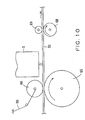
- the follower roller 65 utilizes a spring 80 to press the printer paper 50 against the paper-feeding roller 65, as illustrated in Fig. 10.
- the spring 80 causes the printing paper 50 to move in a reverse direction to a normal feeding direction thereof, which, in turn, causes the paper feeding roller 65 to rotate in reverse, or more specifically, which causes the encoder 13 attached to the paper feeding roller 65 to rotate in reverse.
- the speed calculator 6d produces inaccurate output which is a result of arithmetic operations of the velocity based upon output from the encoder 13, or otherwise, the timer counter used in the arithmetic operations for the velocity by the speed calculator 6d causes overflow which disables the timer counter for detecting accurate velocity.
- the motor control apparatus has a basic arrangement to detect a motor velocity which includes a signal generator producing a first pulse signal proportional in cycle to a motor velocity and a second pulse signal proportional in cycle to the motor velocity and different in phase from the first pulse signal is about one quarter of a single cycle, a pulse edge detector distinctively detecting leading edges and trailing edges of the first and second pulse signals from one another, a time counter measuring a period of time between the pulse edges in the same direction of the same pulse signal, and a velocity converter using the period of time measured by the time counter to sequentially convert it into the motor velocity and thereby detect the motor velocity, and such an arrangement of the invention can greatly enhance a resolution of the detection of the motor velocity and permit constantly accurate detection of the motor velocity.
- the motor control apparatus may have a practical arrangement to detect a motor velocity which includes a signal generator producing a first pulse signal proportional in cycle to a motor velocity and a second pulse signal proportional in cycle to the motor velocity and different in phase from the first pulse signal by about one quarter of a single cycle, a detection condition memory storing a plurality of detection conditions including a condition of distinctively detecting pulse edges in the same direction of the same pulse signal, so as to output either of the detection conditions depending upon a specified condition, a detection condition setting unit specifying the detection conditions received from the detection condition memory, a pulse edge detector detecting part or all of leading and trailing edges of the first and second pulse signals depending upon the detection conditions specified by the detection condition setting unit, a time counter measuring a period of time between the pulse edges detected by the pulse edge detector, and a velocity converter using the period of time measured by the time counter to sequentially convert it into said motor velocity and thereby detect said motor velocity, and such an arrangement of the invention, when the plurality of conditions of encoder pulse edge detection are appropriately combined
- the specified condition may include the motor velocity, the number of the cycles of the first or the second pulse signal, or an amount of actuation by the motor.
- the time counter may simultaneously measure at least four periods of time between the pulse edges in parallel with one another.
- the time counter may measure the periods of time between the pulse edges in the same direction of the same pulse signal when the above-mentioned pulse detector distinctively detects the pulse edges in the same direction of the same pulse signal.
- the detection condition memory and the detection condition setting unit may be comprised of either one of PROM, EEPROM, and ASIC.
- the velocity converter may execute conversion into the motor velocity by dividing a distance corresponding to an interval between the pulse edges by the period of time.
- the control apparatus further includes a comparison reference value memory storing comparison reference values determined for each of the pulse edges, from the one preceding by a specific number of pulse edges to a target edge which is a pulse edge indicating a targeted stop position of an object to be driven by the motor, to the target edge, and a motor stop controller comparing the comparison reference value with the motor velocity for each of the pulse edges from the specific number of the pulse edges before the target edge to the target edge so as to give a command to stop the motor when the motor velocity is equal to or over the comparison reference value.
- the comparison reference value memory may be comprised of either one of PROM, EEPROM, and ASIC while the motor stop controller may be comprised of a CPU.
- the pulse edge detector, the time counter, and the velocity converter may be comprised of a CPU.
- the signal generator may be comprised of an encoder.
- a motor control method will be outlined as follows.
- the method is directed to detecting a motor velocity by performing the steps of distinctively detecting leading and trailing edges of two pulse signals proportional in cycle to the motor velocity and different in phase by about one quarter of the cycle from one another, measuring a period of time between pulse edges in the same direction of the same pulse signal, using the period of time between the pulse edges to sequentially convert it into the motor velocity and thereby detect the motor velocity.
- the motor control method has a basic configuration directed to detecting a motor velocity with greatly enhanced resolution and with constant high accuracy, comprising: a first step of generating a first pulse signal proportional in cycle to a motor velocity and a second pulse signal proportional in cycle to the motor velocity and different in phase from the first pulse signal by about one quarter of a single cycle; a second step of distinctively detecting leading and trailing edges of the first and second pulse signals from one another; a third step of measuring a period of time between the pulse edges in the same direction of the same pulse; and a fourth step of using a measurement result of the period of time to sequentially convert it into the motor velocity and thereby detect the motor velocity.
- the fourth step as mentioned above may include dividing a distance corresponding to an interval between the pulse edges by the period of time to perform the conversion to the motor velocity.
- the control method according to the invention further includes a fifth step of comparing said motor velocity with comparison reference values for individual pulse edges from a pulse edge preceding by a predetermined number of pulse edges to a target edge which is a pulse edge indicating a target stop position of an object to be driven by said motor to said target edge, at respective said pulse edges, and issuing a command to stop the motor when said motor velocity is equal to or over said comparison reference values.
- the motor control method has a practical configuration directed to detecting a motor velocity, comprising: a first step of generating a first pulse signal proportional in cycle to a motor velocity and a second pulse signal proportional in cycle to the motor velocity and different in phase from the first pulse signal by about one quarter of a cycle; a second step responsive to a specified condition to select one of a plurality of conditions of detection which include a condition of distinctively detecting pulse edges in the same direction of the same pulse signal; a third step depending upon the selected condition of detection to detect part or all of leading and trailing edges of the first and second pulse signals; a fourth step of measuring a period of time between the detected pulse edges; a fifth step of using a measurement result of the period of time to sequentially convert it into the motor velocity and thereby detect the motor velocity.
- the specified condition may include the motor velocity, the number of the cycles of the first or the second pulse signal, or an amount of actuation by the motor.
- a period of time between the pulse edges in the same direction of the same pulse may be measured in the fourth step.
- a distance corresponding to an interval between the pulse edges may be divided by the period of time to execute the conversion into the motor velocity.
- the control method according to the invention may further comprise a sixth step of comparing said motor velocity with comparison reference values for individual pulse edges from a pulse edge preceding by a predetermined number of pulse edges to a target edge which is a pulse edge indicating a target stop position of an object to be driven by said motor to said target edge, at respective said pulse edges, and issuing a command to stop the motor when said motor velocity is equal to or over said comparison reference values.
- the pulse signals may be generated by an encoder.
- the encoder may be a linear encoder fixed to a carriage of a serial printer while the motor may be a carriage motor actuating the carriage.
- the encoder may also be a rotary encoder for a paper feeding motor in a serial printer while the motor may be a paper feeding motor that feeds paper in the serial printer.
- the motor control apparatus includes a reverse rotation detector for detecting whether, upon actuation by the motor, reverse rotations are caused in an attachment unit where the encoder is attached, from output pulses from the encoder rotated by rotations of the motor, a first pulse counter counting edges of the output pulses from the encoder after the attachment unit has rotated from a reverse direction to a normal direction when the reverse rotations are caused in the attachment unit, to give a start command when a counted value reaches a first specified value, and a speed calculator receiving the start command when the reverse rotations are caused in the attachment unit, to compute the motor velocity from the output pulses from the encoder.
- the motor control apparatus may further include a second pulse counter which, upon actuation by the motor, counts the edges of the output pulses from the encoder to give a start command when a counted value reaches a second specified value
- the speed calculator may be configured to receive the start command output from the first pulse counter when the reverse rotations are caused in the attachment unit, or receive the start command output from the second pulse counter when the reverse rotations are not caused in the attachment unit, to start computation of the velocity.
- the motor may be a paper feeding motor in a printing machine.
- the motor control apparatus may include a speed controller controlling the motor velocity by referring to a difference between a targeted velocity of the motor and the motor velocity obtained through the computation by the speed calculator.
- the motor control method includes the steps of referring to output pulses from an encoder rotated by rotations of a motor to detect, upon actuation by the motor, whether reverse rotations are caused in an attachment unit where the encoder is attached, counting edges of the output pulses from the encoder after the attachment unit has rotated from a reverse direction to a normal direction when reverse rotations are caused in the attachment unit to issue a start command when a counted value reaches a first specified value, and computing the motor velocity from the output pulses from the encoder when the start command is received.
- the motor control method may further include a step of counting edges of the output pulses from the encoder prior to the step of computing the motor velocity, to issue a start command when a counted value reaches a second specified value or when reverse rotations are not caused in the attachment unit.
- the motor control method may further include a step of controlling the motor velocity from a difference between a targeted velocity of the motor and the computed velocity after the step of computing the motor velocity.
- the motor may be a paper feeding motor in a printing machine.
- the record medium storing control programs for a motor includes the steps of detecting, upon actuation by the motor, if reverse rotations are caused in an attachment unit where an encoder is attached, from output pulses from the encoder rotated by rotations of the motor, counting edges of the output pulses from the encoder after the attachment unit has rotated from a reverse direction to a normal direction, when reverse rotations are caused in the attachment unit, to issue a start command when a counted value reaches a first specified value, and computing the motor velocity when the start command is received, by ring to the output pulses from the encoder.
- the record medium storing computer programs according to the invention stores a computer program to execute any of the steps of the motor control method according to the invention in a computer system.
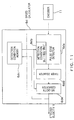
- Fig. 11 is a block diagram showing a configuration of a speed calculator 6d of a DC unit 6 which serves as a motor control apparatus according to the invention while Figs. 12A, 12B, and 12C are timing charts showing conditions of encoder pulse edge detection in the speed calculator 6d in the DC unit 6 which serves as the motor control apparatus according to the invention.
- An overall configuration of the DC unit 6 is similar to that illustrated in a block diagram in Fig. 7 while an overall schematic configuration of an ink jet printer is similar to that illustrated in a block diagram in Fig. 1.
- the speed calculator 6d in the motor control apparatus according to the invention in Fig. 11 is comprised of a pulse edge detector 6da detecting and producing pulse edges of encoder pulses ENC-A and ENC-B received from an encoder 11, depending upon predetermined conditions of pulse edge detection, a detection condition setting unit 6db setting the conditions of pulse edge detection in the pulse edge detector 6da, a detection condition memory 6dc storing more than one conditions of pulse edge detection specified by the detection condition setting unit 6db to output conditions of pulse edge detection corresponding to a motor velocity to the detection condition setting unit 6db for setting of the detection conditions, a timer counter 6dd measuring a period of time between the pulse edges sequentially detected by and released from the pulse edge detector 6da depending upon the specified conditions of pulse edge detection, and a speed converter 6de using a distance corresponding to an interval between the pulse edges and a measurement result of the period of time from the timer counter 6dd under the specified conditions of pulse edge detection to perform arithmetic operations and effect the conversion into a motor
- the motor control apparatus and control method according to the invention are most noteworthy in that two encoder pulses ENC-A and ENC-B received from the encoder 11 have their respective leading and trailing edges, and those pulse edges in the same direction of the same encoder pulse (namely, the encoder pulse of the same channel) are distinctively detected.
- a period of time is measured between the pulse edges in the same direction of the same encoder pulse, and a distance corresponding to an interval between the pulse edges in the same direction of the same encoder pulse and the period of time between the pulse edges are used to perform the conversion into a motor velocity. More specifically, as shown in a timing chart in Fig.
- the period of time between the pulse edges such as a period of time T1 from a leading edge of the encoder pulse ENC-A to an immediately succeeding leading edge of the encoder pulse ENC-A, a period of time T2 from a leading edge of the encoder pulse ENC-B to an immediately succeeding leading edge of the encoder pulse ENC-B, a period of time T3 from a trailing edge of the encoder pulse ENC-A to an immediately succeeding trailing edge of the encoder pulse Enc-A, a period of time T4 from a trailing edge of the encoder pulse ENC-B to an immediately succeeding trailing edge of the encoder pulse ENC-B, and so forth, are sequentially measured by following timings at points of time such as tl, t2, t3, t4, and so forth, and a distance corresponding to an interval between two adjacent leading or trailing edges in the same direction of the same encoder pulse and the period of time between those pulse edges are used to execute into a motor velocity.
- Timing charts shown in Figs. 12B and 12C are similar to those shown in timing charts in Figs. 8A and 8B where conditions of encoder pulse edge detection in the speed calculator 6d of the prior art DC unit 6 are represented.
- detecting the edges of the encoder pulses and then measuring a period of time elapsing for a single cycle of any of the encoder pulse, under the condition of encoder pulse edge detection as shown in Fig. 12A, to execute conversion into the motor velocity can result in shooting troubles which would arise when, under the conditions of encoder pulse edge detection as shown in Figs. 12B and 12C, the edges of the encoder pulses are detected, and the period of time is measured to perform the conversion into the motor velocity.
- a reference period of time is regarded as that from one edge of one of the encoder pulses to an immediately succeeding edge of the other encoder pulse which is equal to one quarter of a single cycle of the encoder pulses, in order to measure the periods of time.
- a desired resolution of detection of the motor velocity can be obtained even by detecting the encoder pulse edges and measuring the corresponding period of time under the condition of encoder pulse edge detection as illustrated in Fig. 12B.
- the speed calculator 6d in the DC unit 6 serving as the motor control apparatus according to the invention as shown in Fig. 11 has a configuration where the conditions of encoder pulse edge detection illustrated in Figs. 12A, 12B, and 12C can be respectively combined with one another. Its operation will be detailed below.
- the detection condition memory 6dc stores three variations of the conditions of encoder pulse edge detection as mentioned in terms of Figs. 12A, 12B, and 12C, and the conditions of encoder pulse edge detection suitable to a specific condition are output to the detection condition setting unit 6db and the velocity converter 6de, respectively.
- the specific condition used here for selectively releasing the conditions of encoder pulse edge detection is a motor velocity value converted from the encoder pulses or the number of cycles of the encoder pulses, as will be explained later. otherwise, the specific condition may include an amount of actuation by the motor, and specifically, a displacement of an object to be driven by the motor.
- the detection condition setting unit 6db receives the conditions of encoder pulse edge detection from the detection condition memory 6dc and specifies them, depending upon the converted value from the encoder pulses into the motor velocity. For instance, the condition of encoder pulse edge detection shown in Fig. 12C is specified for the first single cycle or several cycles after resuming actuation of the motor in its stop mode, and thereafter, the condition of encoder pulse edge detection shown in Fig. 12A is specified when the motor velocity is less than a predetermined value while the condition of encoder pulse edge detection shown in Fig. 12B is specified when the motor velocity is equal to or above the predetermined value.
- the pulse edge detector 6da detects the pulse edges of the encoder pulses ENC-A and ENC-B received from the encoder 11, depending upon the specified condition of pulse edge detection to sequentially output the detected pulse edges to the timer counter 6dd.
- the pulse edge detector 6da regards the pulse edges as the ones of the same type and sequentially issues them without indiscriminate from one another while, when the condition of encoder pulse edge detection shown in Fig. 12A is specified, the pulse edge detector 6da issues leading and trailing edges of the encoder pulse ENC-A and leading and trailing edges of the encoder pulse ENC-B so that each type of the edges of each encoder pulse is identifiable.
- the pulse edge detector 6da issues only leading edges of the encoder pulse ENC-A so that they are distinctive from other pulse edges.
- the timer counter 6dd measures a period of time between the pulse edges output from the pulse edge detector 6da.
- the pulse edges received from the pulse edge detector 6da are respectively identifiable ones of a plurality of different types, the period of time between the same type of the pulse edges is measured; in other words, the period of time between the pulse edges in the same direction is measured.
- the timer counter 6dd is designed to simultaneously measure at least four periods of time between the pulse edges in parallel when the condition of encoder pulse edge detection shown in Fig. 12A is specified, so as to measure the period of time elapsing between the pulse edges in the same direction of the same encoder pulse.
- the timer counter 6dd sequentially outputs a measurement result of the period of time between the pulse edges. In such an event, even when the periods of time between the edges depending upon their respective types are measured, there is no need of producing the results as being identifiable from one another, and hence, it is sufficient to sequentially issue the results without any particular discrimination from one another.
- the velocity converting unit 6de uses a distance corresponding to an interval between the pulse edges and a measurement result of the period of time under the specified conditions of pulse edge detection to execute computation and conversion into the motor velocity.
- An exemplary configuration of the speed calculator 6d described above can have the pulse edge detector 6da, the timer counter 6dd, and the velocity converter 6de respectively comprised of CPU, have the detection condition setting unit 6db comprised of CPU, RAM, or ASIC, and have the detection condition memory 6dc comprised of PROM, EEPROM, or ASIC.
- Fig. 13 is a graph showing a speed of switching settings on the conditions of pulse edge detection shown in Figs. 12A and 12B.
- the motor velocity must be detected with high accuracy during a period of time TY for which the variations of the targeted velocity of the motor are relatively great, the targeted velocity of the motor is relatively low, and the duty ratio of either of the encoder pulses and the phase difference between the encoder pulses are liable to vary, and therefore, it is preferable that the condition of pulse edge detection shown in Fig. 12A may be specified.
- Fig. 12A may preferably be specified rather than that in Fig. 12B.
- a higher targeted velocity of the motor tends to be usually employed for a longer displacement of the object to be driven by the motor, and hence, if a relation of the displacement to the targeted velocity is known in advance, control over the periods TX and TY may be predetermined depending upon the displacement, or control over the period TY' may be predetermined.
- the switching of the settings on the conditions of pulse edge detection may be carried out, depending upon operation abilities of the CPUs which the pulse edge detector 6da, the timer counter 6dd, the velocity converting unit 6de, and the detection condition setting unit 6db are partially or totally comprised of, respectively.
- the pulse edge detector 6da for the encoder pulse edge detection may have a function of a filter.
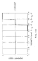
- Fig. 14 is a graph showing an exemplary relation of a velocity (ips: inch per second) in the braking to an overshoot (of the edge) while Fig. 15 is a timing chart illustrating a duration for which the velocity is measured in the braking, braking timings, and the overshoot (of the edges), where periods of time TP, TQ, and TR in Fig. 14 are equivalent to those in Fig. 15.
- Fig. 14 shows a relation of a velocity measured during the period of time TK in the timing chart in Fig. 15 to an overshoot upon running the brake at a pulse edge EDGK.
- the motor stops within a targeted section corresponding to the period of time TP when the velocity during the period of time TK immediately before the braking is in a range of 0.2 ips to less than 0.25 ips.
- the motor overshoots by a distance corresponding to a single edge when the velocity is in a range of 0.25 ips to less than 0.3 ips while it overshoots by a distance corresponding to two edges when the velocity is in a range of 0.3 ips to less than 0.35 ips.
- the motor velocity during the period of time TK immediately before the braking is in a range of 0.2 ips to less than 0.25 ips
- the motor stops within the target section corresponding to the duration TP although the motor overshoots by a distance corresponding to a single edge to stop within a section corresponding to the period of time TQ when the velocity is in a range of 0.25 ips to less than 0.3 ips, while it overshoots by a distance corresponding to two edges to stop within a section corresponding to the duration TR when the velocity is in a range of 0.3 ips to less than 0.35 ips.
- Fig. 16 is a timing chart showing an example of the motor stop control, where a period of time TY is a duration of deceleration control, a period of time TZ is a duration of stop control, a pulse edge EDG (ref-0) is a target edge, and a section corresponding to a duration from the pulse EDG(ref-0) to a pulse edge right after it is a target stop position.
- the deceleration control for the duration TY aims at reducing the motor velocity down to less than 0.35 ips at a point of time of the pulse edge EDG(ref-4), a protective operation control is taken, when the motor velocity is 0.35 ips or higher at the time of the pulse edge EDG(ref-3), so as to disconnect electric power to the motor at this point of time.
- Such motor stop control is implemented, for example, by giving, to CPU, factors such as the targeted stop position, the detected velocity V received from the speed calculator 6d, and a comparison reference speed at each pulse edge for the duration TZ of stop control and then by transferring an output signal indicating the comparison result from the CPU to a D/A converter 6j.
- a comparison reference speed at each pulse edge for the duration TZ of stop control can be stored and retained in a device such as PROM, EEPROM, or ASIC.
- a rotary encoder 13 for the PF motor 1 may be a substitution for it.
- the motor in the above description may be the carriage motor 4 driving the carriage 3 or the paper feeding motor 1 used to feed paper sheets.
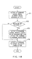
- FIG. 17 A configuration of the modified embodiment is shown in Fig. 17 while its operation is shown in a flow chart in Fig. 18.
- the embodiment of the motor control apparatus has additional components to the prior art motor control apparatus (DC unit) 6 in Fig. 7 such as pulse counters 6p and 6r, a reverse rotation detector 6q, an AND gate 6s, and an OR gate 6t. Description of components other than the pulse counters 6p and 6r, the reverse rotation detector 6q, the AND gate 6s, and the OR gate 6t is omitted since like components have been described with reference to Fig. 7.
- the reverse rotation detector 6q detects whether an attachment unit (paper feeding roller 65) where the encoder 13 is attached is rotated in the reverse direction, by referring to output from the encoder 13 (see step F2 in Fig. 18). If it is determined that the attachment unit is not rotated in the reverse direction, a command signal is transferred from the reverse rotation detector 6q to the AND gate 6s to proceed to step F4 in Fig. 18 which will be mentioned hereinafter.
- a command signal is transferred from the reverse rotation detector 6q to the pulse counter 6r when the attachment unit where the encoder 13 is attached turns to rotate from the reverse direction to the normal direction.
- the command signal is received by the pulse counter 6r, the number of the edges of the output pulses ENC-A and ENC-B from the encoder 13 is counted after the reverse rotations of the attachment unit fixed to the encoder 13 turns to the normal rotations.
- a command signal is transferred from the pulse counter 6r to the OR gate 6t (see step F3 in Fig. 18).
- the reverse rotation detector 6q detects normal rotations at time t 2 , and in response to the detection, the command signal is transferred to the pulse counter 6r.
- the pulse counter 6r Upon and after the incoming of a next pulse edge at time t 3 , the pulse counter 6r counts the number of the pulse edges, and when the count value N 2 reaches 5 at time t 4 , a command signal is transferred from the pulse counter 6r to the OR gate 6t.
- the command signals are transferred from the pulse counter 6p and the reverse rotation detector 6q to the AND gate 6s, respectively, and hence, a command signal is output to the OR gate 6t by the AND gate 6s.
- the command signal is transferred to the OR gate 6t from the AND gate when it is determined that the attachment unit to the encoder 13 is not rotated in reverse, and it is from the pulse counter 6r when the attachment unit is rotated in reverse. Subsequently, a start command to start computing a velocity is sent to the speed calculator 6d by the OR gate 6t (see step F4 in Fig. 18).
- the speed calculator 6d does not start computing the velocity as has been described with reference to Fig. 7 until it receives the start command.
- the timer counter used in the speed calculator 6d for the velocity computation can be prevented from overflowing even if the attachment unit to the encoder 13 is rotated in reverse upon the actuation of the PF motor 1.
- DC motor is employed as the preferred embodiment in the above description, motors such as an AC motor should be used in some applications.
- the predetermined number N 2 may be altered depending upon a frequency of use of the printer, environmental conditions, and so on.
- the velocity can be detected accurately even when the attachment unit to the encoder is rotated in reverse upon the actuation of the motor.
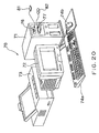
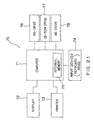
- Fig. 20 is a diagram showing external configurations of a record medium storing programs to execute the motor control method according to the invention and of a computer system in which the record medium is used while Fig. 21 is a block diagram showing an internal arrangement of the computer system illustrated in Fig. 20.
- a computer system 70 shown in Fig. 20 is comprised of a computer main body 71 housed in a cabinet shaped in varieties such as in a mini-tower, a display 72 such as a CRT (cathode ray tube), a plasma display and a liquid crystal display, a printer 73 serving as a record producing device, a key board 74a and a mouse 74b serving as input devices, a flexible disk drive 76, and a CD-ROM drive 77.
- Fig. 21 is a block diagram showing the arrangement of the computer system 70, where internal memories 75 such as RAM (random access memory) and external memories 78 such as hard disk drive unit are further provided within the cabinet enclosing the computer main body 71.
- the record mediums include a flexible disk 81 and CD-ROM (read only memory), and in addition to that, MO (magnetic optical) disk, DVD (digital versatile disk), other types of optical recording disks, card memory, magnetic tape, etc. may be used.
- MO magnetic optical
- DVD digital versatile disk
Priority Applications (1)
| Application Number | Priority Date | Filing Date | Title |
|---|---|---|---|
| EP06075410A EP1681173B1 (de) | 1999-12-24 | 2000-12-21 | Vorrichtung und Verfahren zur Motorsteuerung |
Applications Claiming Priority (4)
| Application Number | Priority Date | Filing Date | Title |
|---|---|---|---|
| JP36802999 | 1999-12-24 | ||
| JP36802999A JP3705061B2 (ja) | 1999-12-24 | 1999-12-24 | モータの制御装置およびその制御方法ならびにモータの制御プログラムを記録した記録媒体 |
| JP2000032045 | 2000-02-09 | ||
| JP2000032045A JP3832174B2 (ja) | 2000-02-09 | 2000-02-09 | モータ制御装置及び制御方法 |
Related Child Applications (1)
| Application Number | Title | Priority Date | Filing Date |
|---|---|---|---|
| EP06075410A Division EP1681173B1 (de) | 1999-12-24 | 2000-12-21 | Vorrichtung und Verfahren zur Motorsteuerung |
Publications (2)
| Publication Number | Publication Date |
|---|---|
| EP1110744A1 true EP1110744A1 (de) | 2001-06-27 |
| EP1110744B1 EP1110744B1 (de) | 2006-09-13 |
Family
ID=26581967
Family Applications (2)
| Application Number | Title | Priority Date | Filing Date |
|---|---|---|---|
| EP00311536A Expired - Lifetime EP1110744B1 (de) | 1999-12-24 | 2000-12-21 | Vorrichtung und Verfahren zur Motorsteuerung |
| EP06075410A Expired - Lifetime EP1681173B1 (de) | 1999-12-24 | 2000-12-21 | Vorrichtung und Verfahren zur Motorsteuerung |
Family Applications After (1)
| Application Number | Title | Priority Date | Filing Date |
|---|---|---|---|
| EP06075410A Expired - Lifetime EP1681173B1 (de) | 1999-12-24 | 2000-12-21 | Vorrichtung und Verfahren zur Motorsteuerung |
Country Status (4)
| Country | Link |
|---|---|
| US (1) | US6418274B2 (de) |
| EP (2) | EP1110744B1 (de) |
| AT (2) | ATE410309T1 (de) |
| DE (2) | DE60030667T2 (de) |
Cited By (1)
| Publication number | Priority date | Publication date | Assignee | Title |
|---|---|---|---|---|
| CN113483802A (zh) * | 2021-07-19 | 2021-10-08 | 合肥哈工高创智能装备有限公司 | 一种防止装盒机机械传动异常的快速预警保护系统及方法 |
Families Citing this family (19)
| Publication number | Priority date | Publication date | Assignee | Title |
|---|---|---|---|---|
| EP1129856B1 (de) * | 2000-03-03 | 2007-01-17 | Seiko Epson Corporation | Motorsteuerungsvorrichtung und -verfahren |
| JP3832712B2 (ja) * | 2000-09-21 | 2006-10-11 | セイコーエプソン株式会社 | 印刷制御装置および制御方法ならびに印刷制御プログラムを記録した記録媒体 |
| US7084597B2 (en) * | 2002-06-03 | 2006-08-01 | Denso Corporation | Motor control apparatus |
| US7317313B2 (en) * | 2002-11-14 | 2008-01-08 | Measurement Specialties, Inc. | Magnetic encoder apparatus |
| JP4272565B2 (ja) * | 2003-07-18 | 2009-06-03 | 株式会社リコー | ベルト駆動制御装置及び画像形成装置 |
| US7821216B2 (en) * | 2003-09-12 | 2010-10-26 | Brother Kogyo Kabushiki Kaisha | Motor control method and control device |
| JP4356447B2 (ja) * | 2003-12-19 | 2009-11-04 | 株式会社デンソー | 電動アクチュエータシステム、及び車両用空調装置。 |
| JP4124126B2 (ja) * | 2004-01-14 | 2008-07-23 | ブラザー工業株式会社 | モータ制御装置 |
| US20050153718A1 (en) * | 2004-01-14 | 2005-07-14 | International Business Machines Corporation | Apparatus, system and method of delivering a text message to a landline telephone |
| JP4059213B2 (ja) * | 2004-02-27 | 2008-03-12 | ブラザー工業株式会社 | モータ制御装置およびモータ制御方法 |
| US7183935B2 (en) * | 2004-10-14 | 2007-02-27 | Rockwell Automation Technologies, Inc. | Method and apparatus for determining motor velocity using edge mode hysteresis with a finite impulse response average filter |
| JP2007011611A (ja) * | 2005-06-29 | 2007-01-18 | Ricoh Co Ltd | 位置決め制御装置、位置決め制御方法、その方法をコンピュータに実行させるプログラム、画像形成装置、および記録媒体 |
| ES2402743T3 (es) * | 2008-01-17 | 2013-05-08 | B.T.S.R. International S.P.A. | Sistema para controlar la alimentación de una máquina con un hilo o alambre y procedimiento correspondiente |
| US8333450B2 (en) * | 2008-12-16 | 2012-12-18 | Fuji Xerox Co., Ltd. | Speed calculation device, speed estimation device, image forming device, and storage medium |
| US8310178B2 (en) * | 2009-02-27 | 2012-11-13 | Canon Kabushiki Kaisha | Motor control apparatus and image forming apparatus |
| JP2010210347A (ja) * | 2009-03-09 | 2010-09-24 | Brother Ind Ltd | エンコーダ信号処理装置、エンコーダ信号処理方法、及び搬送装置 |
| JP6160189B2 (ja) * | 2012-06-01 | 2017-07-12 | 株式会社リコー | モータ制御装置、画像処理装置、及びモータ制御方法 |
| CN104579096B (zh) * | 2015-01-12 | 2017-12-05 | 深圳市英威腾电气股份有限公司 | 一种电机的控制方法和装置 |
| JP6895531B2 (ja) * | 2017-10-10 | 2021-06-30 | 株式会社日立産機システム | 速度算出装置および電力変換装置 |
Citations (5)
| Publication number | Priority date | Publication date | Assignee | Title |
|---|---|---|---|---|
| US4216415A (en) * | 1977-05-31 | 1980-08-05 | Nippon Electric Co., Ltd. | Position control system comprising a digital algebraic adder circuit |
| EP0465850A2 (de) * | 1990-06-11 | 1992-01-15 | Canon Kabushiki Kaisha | Aufzeichnungsvorrichtung |
| EP0680829A2 (de) * | 1994-05-03 | 1995-11-08 | Hewlett-Packard Company | Optisches Steuersystem für Aufzeichnungsträgeranordnungen in Druckern |
| US5926192A (en) * | 1995-09-05 | 1999-07-20 | Brother Kogyo Kabushiki Kaisha | Print control system |
| EP0945277A2 (de) * | 1998-03-26 | 1999-09-29 | Brother Kogyo Kabushiki Kaisha | Druckvorrichtung mit Taktimpulsgenerator |
Family Cites Families (7)
| Publication number | Priority date | Publication date | Assignee | Title |
|---|---|---|---|---|
| KR0163711B1 (ko) * | 1992-10-01 | 1999-01-15 | 윤종용 | 광 디스크 시스템의 스핀들 모터 제어 회로 |
| US5433541A (en) * | 1992-12-15 | 1995-07-18 | Nec Corporation | Control device for controlling movement of a printing head carriage and control method for controlling the same |
| JP3200510B2 (ja) * | 1993-09-17 | 2001-08-20 | 松下電器産業株式会社 | モータ制御装置 |
| JP3392666B2 (ja) * | 1996-11-13 | 2003-03-31 | ナスコ株式会社 | 数値制御往復走行加工機の制御方法 |
| US5982134A (en) * | 1997-05-20 | 1999-11-09 | Seiko Epson Corporation | Method and apparatus for driving a stepping motor |
| US6081091A (en) * | 1999-03-08 | 2000-06-27 | Motorola, Inc. | Motor controller, integrated circuit, and method of controlling a motor |
| US6302514B1 (en) * | 1999-09-03 | 2001-10-16 | Lexmark International, Inc. | Method and apparatus for automatically correcting the fire timing of a printhead carrier due to linear encoder velocity errors |
-
2000
- 2000-12-21 DE DE60030667T patent/DE60030667T2/de not_active Expired - Lifetime
- 2000-12-21 DE DE60040494T patent/DE60040494D1/de not_active Expired - Lifetime
- 2000-12-21 AT AT06075410T patent/ATE410309T1/de not_active IP Right Cessation
- 2000-12-21 AT AT00311536T patent/ATE339320T1/de not_active IP Right Cessation
- 2000-12-21 EP EP00311536A patent/EP1110744B1/de not_active Expired - Lifetime
- 2000-12-21 EP EP06075410A patent/EP1681173B1/de not_active Expired - Lifetime
- 2000-12-22 US US09/742,107 patent/US6418274B2/en not_active Expired - Lifetime
Patent Citations (5)
| Publication number | Priority date | Publication date | Assignee | Title |
|---|---|---|---|---|
| US4216415A (en) * | 1977-05-31 | 1980-08-05 | Nippon Electric Co., Ltd. | Position control system comprising a digital algebraic adder circuit |
| EP0465850A2 (de) * | 1990-06-11 | 1992-01-15 | Canon Kabushiki Kaisha | Aufzeichnungsvorrichtung |
| EP0680829A2 (de) * | 1994-05-03 | 1995-11-08 | Hewlett-Packard Company | Optisches Steuersystem für Aufzeichnungsträgeranordnungen in Druckern |
| US5926192A (en) * | 1995-09-05 | 1999-07-20 | Brother Kogyo Kabushiki Kaisha | Print control system |
| EP0945277A2 (de) * | 1998-03-26 | 1999-09-29 | Brother Kogyo Kabushiki Kaisha | Druckvorrichtung mit Taktimpulsgenerator |
Cited By (1)
| Publication number | Priority date | Publication date | Assignee | Title |
|---|---|---|---|---|
| CN113483802A (zh) * | 2021-07-19 | 2021-10-08 | 合肥哈工高创智能装备有限公司 | 一种防止装盒机机械传动异常的快速预警保护系统及方法 |
Also Published As
| Publication number | Publication date |
|---|---|
| ATE339320T1 (de) | 2006-10-15 |
| ATE410309T1 (de) | 2008-10-15 |
| DE60030667D1 (de) | 2006-10-26 |
| DE60040494D1 (de) | 2008-11-20 |
| EP1681173B1 (de) | 2008-10-08 |
| EP1681173A1 (de) | 2006-07-19 |
| DE60030667T2 (de) | 2007-09-13 |
| US20010024101A1 (en) | 2001-09-27 |
| US6418274B2 (en) | 2002-07-09 |
| EP1110744B1 (de) | 2006-09-13 |
Similar Documents
| Publication | Publication Date | Title |
|---|---|---|
| EP1110744B1 (de) | Vorrichtung und Verfahren zur Motorsteuerung | |
| EP1602504B1 (de) | Motorsteuerungsvorrichtung und -verfahren | |
| EP1124320B1 (de) | Verfahren und Vorrichtung zur Motorsteuerung | |
| JP3859115B2 (ja) | プリンタ用モータの制御装置および制御方法ならびに制御プログラムを記録した記録媒体 | |
| JP3832174B2 (ja) | モータ制御装置及び制御方法 | |
| JP3780804B2 (ja) | モータ制御装置及び制御方法 | |
| JP3570617B2 (ja) | Dcモータ制御装置及び制御方法 | |
| EP1080928B1 (de) | Steuereinheit und Verfahren zur Steuerung eines Motors für einen Drucker und Steuerungsprogramm speicherndes Speichermedium | |
| JP3757834B2 (ja) | モータ制御装置及びプリンタ | |
| JP4026330B2 (ja) | モータ制御方法、モータ制御装置、プリンタ、コンピュータプログラム、及び、コンピュータシステム | |
| JP2005103835A (ja) | プラテンギャップ調整装置及び印刷装置並びにモータ制御装置 | |
| JP3705061B2 (ja) | モータの制御装置およびその制御方法ならびにモータの制御プログラムを記録した記録媒体 | |
| JP3818496B2 (ja) | プリンタ制御装置及びプリンタ制御方法 | |
| JP3893853B2 (ja) | プリンタ用モータの制御装置および制御方法 | |
| JP2005231243A (ja) | プリンタ制御装置及びプリンタ制御方法並びにプリンタ | |
| JP3871181B2 (ja) | 印刷制御装置および制御方法ならびに印刷制御プログラムを記録した記録媒体 | |
| JP4026331B2 (ja) | モータ駆動方法、モータ駆動装置、プリンタ、コンピュータプログラム、及び、コンピュータシステム | |
| JP4432055B2 (ja) | プリンタ用モータの制御装置および制御方法 | |
| JP2001180054A (ja) | 印刷制御装置および印刷制御方法 | |
| JP2001315395A (ja) | 印刷制御装置および印刷制御方法ならびに印刷制御プログラムを記録した記録媒体 | |
| JP2005200222A (ja) | 印刷制御装置および制御方法ならびに印刷制御プログラムを記録した記録媒体 | |
| JP2001078475A (ja) | モータ制御装置及び制御方法 |
Legal Events
| Date | Code | Title | Description |
|---|---|---|---|
| PUAI | Public reference made under article 153(3) epc to a published international application that has entered the european phase |
Free format text: ORIGINAL CODE: 0009012 |
|
| AK | Designated contracting states |
Kind code of ref document: A1 Designated state(s): AT BE CH CY DE DK ES FI FR GB GR IE IT LI LU MC NL PT SE TR |
|
| AX | Request for extension of the european patent |
Free format text: AL;LT;LV;MK;RO;SI |
|
| 17P | Request for examination filed |
Effective date: 20011210 |
|
| AKX | Designation fees paid |
Free format text: AT BE CH CY DE DK ES FI FR GB GR IE IT LI LU MC NL PT SE TR |
|
| GRAP | Despatch of communication of intention to grant a patent |
Free format text: ORIGINAL CODE: EPIDOSNIGR1 |
|
| GRAS | Grant fee paid |
Free format text: ORIGINAL CODE: EPIDOSNIGR3 |
|
| GRAA | (expected) grant |
Free format text: ORIGINAL CODE: 0009210 |
|
| AK | Designated contracting states |
Kind code of ref document: B1 Designated state(s): AT BE CH CY DE DK ES FI FR GB GR IE IT LI LU MC NL PT SE TR |
|
| PG25 | Lapsed in a contracting state [announced via postgrant information from national office to epo] |
Ref country code: IT Free format text: LAPSE BECAUSE OF FAILURE TO SUBMIT A TRANSLATION OF THE DESCRIPTION OR TO PAY THE FEE WITHIN THE PRESCRIBED TIME-LIMIT;WARNING: LAPSES OF ITALIAN PATENTS WITH EFFECTIVE DATE BEFORE 2007 MAY HAVE OCCURRED AT ANY TIME BEFORE 2007. THE CORRECT EFFECTIVE DATE MAY BE DIFFERENT FROM THE ONE RECORDED. Effective date: 20060913 Ref country code: FI Free format text: LAPSE BECAUSE OF FAILURE TO SUBMIT A TRANSLATION OF THE DESCRIPTION OR TO PAY THE FEE WITHIN THE PRESCRIBED TIME-LIMIT Effective date: 20060913 Ref country code: AT Free format text: LAPSE BECAUSE OF FAILURE TO SUBMIT A TRANSLATION OF THE DESCRIPTION OR TO PAY THE FEE WITHIN THE PRESCRIBED TIME-LIMIT Effective date: 20060913 Ref country code: CH Free format text: LAPSE BECAUSE OF FAILURE TO SUBMIT A TRANSLATION OF THE DESCRIPTION OR TO PAY THE FEE WITHIN THE PRESCRIBED TIME-LIMIT Effective date: 20060913 Ref country code: LI Free format text: LAPSE BECAUSE OF FAILURE TO SUBMIT A TRANSLATION OF THE DESCRIPTION OR TO PAY THE FEE WITHIN THE PRESCRIBED TIME-LIMIT Effective date: 20060913 Ref country code: NL Free format text: LAPSE BECAUSE OF FAILURE TO SUBMIT A TRANSLATION OF THE DESCRIPTION OR TO PAY THE FEE WITHIN THE PRESCRIBED TIME-LIMIT Effective date: 20060913 Ref country code: BE Free format text: LAPSE BECAUSE OF FAILURE TO SUBMIT A TRANSLATION OF THE DESCRIPTION OR TO PAY THE FEE WITHIN THE PRESCRIBED TIME-LIMIT Effective date: 20060913 |
|
| REG | Reference to a national code |
Ref country code: GB Ref legal event code: FG4D |
|
| REG | Reference to a national code |
Ref country code: CH Ref legal event code: EP |
|
| REG | Reference to a national code |
Ref country code: IE Ref legal event code: FG4D |
|
| REF | Corresponds to: |
Ref document number: 60030667 Country of ref document: DE Date of ref document: 20061026 Kind code of ref document: P |
|
| PG25 | Lapsed in a contracting state [announced via postgrant information from national office to epo] |
Ref country code: SE Free format text: LAPSE BECAUSE OF FAILURE TO SUBMIT A TRANSLATION OF THE DESCRIPTION OR TO PAY THE FEE WITHIN THE PRESCRIBED TIME-LIMIT Effective date: 20061213 Ref country code: DK Free format text: LAPSE BECAUSE OF FAILURE TO SUBMIT A TRANSLATION OF THE DESCRIPTION OR TO PAY THE FEE WITHIN THE PRESCRIBED TIME-LIMIT Effective date: 20061213 |
|
| PG25 | Lapsed in a contracting state [announced via postgrant information from national office to epo] |
Ref country code: IE Free format text: LAPSE BECAUSE OF NON-PAYMENT OF DUE FEES Effective date: 20061221 |
|
| PG25 | Lapsed in a contracting state [announced via postgrant information from national office to epo] |
Ref country code: ES Free format text: LAPSE BECAUSE OF FAILURE TO SUBMIT A TRANSLATION OF THE DESCRIPTION OR TO PAY THE FEE WITHIN THE PRESCRIBED TIME-LIMIT Effective date: 20061224 |
|
| PG25 | Lapsed in a contracting state [announced via postgrant information from national office to epo] |
Ref country code: MC Free format text: LAPSE BECAUSE OF NON-PAYMENT OF DUE FEES Effective date: 20061231 |
|
| NLV1 | Nl: lapsed or annulled due to failure to fulfill the requirements of art. 29p and 29m of the patents act | ||
| PG25 | Lapsed in a contracting state [announced via postgrant information from national office to epo] |
Ref country code: PT Free format text: LAPSE BECAUSE OF FAILURE TO SUBMIT A TRANSLATION OF THE DESCRIPTION OR TO PAY THE FEE WITHIN THE PRESCRIBED TIME-LIMIT Effective date: 20070302 |
|
| ET | Fr: translation filed | ||
| REG | Reference to a national code |
Ref country code: CH Ref legal event code: PL |
|
| PLBE | No opposition filed within time limit |
Free format text: ORIGINAL CODE: 0009261 |
|
| STAA | Information on the status of an ep patent application or granted ep patent |
Free format text: STATUS: NO OPPOSITION FILED WITHIN TIME LIMIT |
|
| 26N | No opposition filed |
Effective date: 20070614 |
|
| PG25 | Lapsed in a contracting state [announced via postgrant information from national office to epo] |
Ref country code: GR Free format text: LAPSE BECAUSE OF FAILURE TO SUBMIT A TRANSLATION OF THE DESCRIPTION OR TO PAY THE FEE WITHIN THE PRESCRIBED TIME-LIMIT Effective date: 20061214 |
|
| PG25 | Lapsed in a contracting state [announced via postgrant information from national office to epo] |
Ref country code: TR Free format text: LAPSE BECAUSE OF FAILURE TO SUBMIT A TRANSLATION OF THE DESCRIPTION OR TO PAY THE FEE WITHIN THE PRESCRIBED TIME-LIMIT Effective date: 20060913 Ref country code: LU Free format text: LAPSE BECAUSE OF NON-PAYMENT OF DUE FEES Effective date: 20061221 |
|
| PG25 | Lapsed in a contracting state [announced via postgrant information from national office to epo] |
Ref country code: CY Free format text: LAPSE BECAUSE OF FAILURE TO SUBMIT A TRANSLATION OF THE DESCRIPTION OR TO PAY THE FEE WITHIN THE PRESCRIBED TIME-LIMIT Effective date: 20060913 |
|
| REG | Reference to a national code |
Ref country code: FR Ref legal event code: PLFP Year of fee payment: 16 |
|
| REG | Reference to a national code |
Ref country code: FR Ref legal event code: PLFP Year of fee payment: 17 |
|
| REG | Reference to a national code |
Ref country code: FR Ref legal event code: PLFP Year of fee payment: 18 |
|
| PGFP | Annual fee paid to national office [announced via postgrant information from national office to epo] |
Ref country code: FR Payment date: 20171113 Year of fee payment: 18 Ref country code: DE Payment date: 20171212 Year of fee payment: 18 |
|
| PGFP | Annual fee paid to national office [announced via postgrant information from national office to epo] |
Ref country code: GB Payment date: 20171220 Year of fee payment: 18 |
|
| REG | Reference to a national code |
Ref country code: DE Ref legal event code: R119 Ref document number: 60030667 Country of ref document: DE |
|
| GBPC | Gb: european patent ceased through non-payment of renewal fee |
Effective date: 20181221 |
|
| PG25 | Lapsed in a contracting state [announced via postgrant information from national office to epo] |
Ref country code: FR Free format text: LAPSE BECAUSE OF NON-PAYMENT OF DUE FEES Effective date: 20181231 Ref country code: DE Free format text: LAPSE BECAUSE OF NON-PAYMENT OF DUE FEES Effective date: 20190702 |
|
| PG25 | Lapsed in a contracting state [announced via postgrant information from national office to epo] |
Ref country code: GB Free format text: LAPSE BECAUSE OF NON-PAYMENT OF DUE FEES Effective date: 20181221 |