EP1108843A2 - Justierbares Band - Google Patents
Justierbares Band Download PDFInfo
- Publication number
- EP1108843A2 EP1108843A2 EP00127492A EP00127492A EP1108843A2 EP 1108843 A2 EP1108843 A2 EP 1108843A2 EP 00127492 A EP00127492 A EP 00127492A EP 00127492 A EP00127492 A EP 00127492A EP 1108843 A2 EP1108843 A2 EP 1108843A2
- Authority
- EP
- European Patent Office
- Prior art keywords
- tab
- clamping element
- holding piece
- fitting according
- adjustable fitting
- Prior art date
- Legal status (The legal status is an assumption and is not a legal conclusion. Google has not performed a legal analysis and makes no representation as to the accuracy of the status listed.)
- Granted
Links
Images

Classifications
-
- E—FIXED CONSTRUCTIONS
- E05—LOCKS; KEYS; WINDOW OR DOOR FITTINGS; SAFES
- E05D—HINGES OR SUSPENSION DEVICES FOR DOORS, WINDOWS OR WINGS
- E05D5/00—Construction of single parts, e.g. the parts for attachment
- E05D5/02—Parts for attachment, e.g. flaps
- E05D5/0246—Parts for attachment, e.g. flaps for attachment to glass panels
-
- A—HUMAN NECESSITIES
- A47—FURNITURE; DOMESTIC ARTICLES OR APPLIANCES; COFFEE MILLS; SPICE MILLS; SUCTION CLEANERS IN GENERAL
- A47K—SANITARY EQUIPMENT; ACCESSORIES THEREFOR, e.g. TOILET ACCESSORIES
- A47K3/00—Baths; Showers; Appurtenances therefor
- A47K3/28—Showers or bathing douches
- A47K3/30—Screens or collapsible cabinets for showers or baths
- A47K3/36—Articulated screens
-
- E—FIXED CONSTRUCTIONS
- E05—LOCKS; KEYS; WINDOW OR DOOR FITTINGS; SAFES
- E05D—HINGES OR SUSPENSION DEVICES FOR DOORS, WINDOWS OR WINGS
- E05D7/00—Hinges or pivots of special construction
- E05D7/04—Hinges adjustable relative to the wing or the frame
-
- A—HUMAN NECESSITIES
- A47—FURNITURE; DOMESTIC ARTICLES OR APPLIANCES; COFFEE MILLS; SPICE MILLS; SUCTION CLEANERS IN GENERAL
- A47K—SANITARY EQUIPMENT; ACCESSORIES THEREFOR, e.g. TOILET ACCESSORIES
- A47K3/00—Baths; Showers; Appurtenances therefor
- A47K3/28—Showers or bathing douches
- A47K3/30—Screens or collapsible cabinets for showers or baths
- A47K2003/307—Adjustable connections to the wall
-
- E—FIXED CONSTRUCTIONS
- E05—LOCKS; KEYS; WINDOW OR DOOR FITTINGS; SAFES
- E05D—HINGES OR SUSPENSION DEVICES FOR DOORS, WINDOWS OR WINGS
- E05D5/00—Construction of single parts, e.g. the parts for attachment
- E05D5/02—Parts for attachment, e.g. flaps
- E05D5/0246—Parts for attachment, e.g. flaps for attachment to glass panels
- E05D2005/0261—Parts for attachment, e.g. flaps for attachment to glass panels connecting two or more glass panels
- E05D2005/0269—Parts for attachment, e.g. flaps for attachment to glass panels connecting two or more glass panels the panels being coplanar
-
- E—FIXED CONSTRUCTIONS
- E05—LOCKS; KEYS; WINDOW OR DOOR FITTINGS; SAFES
- E05Y—INDEXING SCHEME ASSOCIATED WITH SUBCLASSES E05D AND E05F, RELATING TO CONSTRUCTION ELEMENTS, ELECTRIC CONTROL, POWER SUPPLY, POWER SIGNAL OR TRANSMISSION, USER INTERFACES, MOUNTING OR COUPLING, DETAILS, ACCESSORIES, AUXILIARY OPERATIONS NOT OTHERWISE PROVIDED FOR, APPLICATION THEREOF
- E05Y2600/00—Mounting or coupling arrangements for elements provided for in this subclass
- E05Y2600/50—Mounting methods; Positioning
- E05Y2600/52—Toolless
- E05Y2600/526—Gluing or cementing
-
- E—FIXED CONSTRUCTIONS
- E05—LOCKS; KEYS; WINDOW OR DOOR FITTINGS; SAFES
- E05Y—INDEXING SCHEME ASSOCIATED WITH SUBCLASSES E05D AND E05F, RELATING TO CONSTRUCTION ELEMENTS, ELECTRIC CONTROL, POWER SUPPLY, POWER SIGNAL OR TRANSMISSION, USER INTERFACES, MOUNTING OR COUPLING, DETAILS, ACCESSORIES, AUXILIARY OPERATIONS NOT OTHERWISE PROVIDED FOR, APPLICATION THEREOF
- E05Y2800/00—Details, accessories and auxiliary operations not otherwise provided for
- E05Y2800/15—Applicability
- E05Y2800/16—Applicable on combinations of fixed and movable wings
- E05Y2800/162—Applicable on combinations of fixed and movable wings the wings being coplanar when the movable wing is in the closed position
-
- E—FIXED CONSTRUCTIONS
- E05—LOCKS; KEYS; WINDOW OR DOOR FITTINGS; SAFES
- E05Y—INDEXING SCHEME ASSOCIATED WITH SUBCLASSES E05D AND E05F, RELATING TO CONSTRUCTION ELEMENTS, ELECTRIC CONTROL, POWER SUPPLY, POWER SIGNAL OR TRANSMISSION, USER INTERFACES, MOUNTING OR COUPLING, DETAILS, ACCESSORIES, AUXILIARY OPERATIONS NOT OTHERWISE PROVIDED FOR, APPLICATION THEREOF
- E05Y2900/00—Application of doors, windows, wings or fittings thereof
- E05Y2900/10—Application of doors, windows, wings or fittings thereof for buildings or parts thereof
- E05Y2900/114—Application of doors, windows, wings or fittings thereof for buildings or parts thereof for showers
-
- E—FIXED CONSTRUCTIONS
- E06—DOORS, WINDOWS, SHUTTERS, OR ROLLER BLINDS IN GENERAL; LADDERS
- E06B—FIXED OR MOVABLE CLOSURES FOR OPENINGS IN BUILDINGS, VEHICLES, FENCES OR LIKE ENCLOSURES IN GENERAL, e.g. DOORS, WINDOWS, BLINDS, GATES
- E06B3/00—Window sashes, door leaves, or like elements for closing wall or like openings; Layout of fixed or moving closures, e.g. windows in wall or like openings; Features of rigidly-mounted outer frames relating to the mounting of wing frames
- E06B3/02—Wings made completely of glass
-
- E—FIXED CONSTRUCTIONS
- E06—DOORS, WINDOWS, SHUTTERS, OR ROLLER BLINDS IN GENERAL; LADDERS
- E06B—FIXED OR MOVABLE CLOSURES FOR OPENINGS IN BUILDINGS, VEHICLES, FENCES OR LIKE ENCLOSURES IN GENERAL, e.g. DOORS, WINDOWS, BLINDS, GATES
- E06B3/00—Window sashes, door leaves, or like elements for closing wall or like openings; Layout of fixed or moving closures, e.g. windows in wall or like openings; Features of rigidly-mounted outer frames relating to the mounting of wing frames
- E06B3/54—Fixing of glass panes or like plates
- E06B3/5481—Fixing of glass panes or like plates by means of discrete fixing elements, e.g. glazing clips, glaziers points
Definitions
- the invention relates to an adjustable fitting for fastening a Glass element on an adjacent element.
- a frame for fire doors is known from EP 0 875 649 A2, wherein the frame has slotted cavities at least in the area of the hinges has, in the band tabs of the tapes can be inserted.
- the attachment the hinge flap on the frame can have a not described Adhesive connection is made. Belt adjustment devices or the band flap are not provided.
- the fitting according to the invention according to claim 1 has the Advantage that the production of glass elements is simplified.
- the Glass elements are e.g. B. for door systems and shower cubicles or Shower walls used that are rigid or pivotable on adjacent ones (Glass) elements are arranged.
- Door or shower systems made of glass elements are subject to the sensitivity of the material to special requirements the fastening technology to the neighboring elements. possibilities to adjust the fitting must be available in order to Avoid bumping edges that are particularly easily damaged can be. Furthermore, the adjustment causes tension largely prevented in the glass panes.
- the tab can be clamped between a holding piece and a clamping element, the holding piece is directly non-positively and positively to the Glass element is glued. It is advantageous in the corresponding Wall of the holding piece formed a groove for receiving adhesive, to prevent it from escaping sideways.
- the clamping element is by means of fasteners through a recess in the tab connected to the holding piece.
- the holding piece or the clamping element has an approach, the with play in the complementary recess of the tab protrudes.
- the game defines the setting range and the shape of the recess or the approach defines the possible adjustment directions. At least one horizontal adjustment is advantageously possible.
- the approach can be integrally on the holding piece or on the clamping element be trained.
- one or several approaches carried out as individual parts, in a corresponding manner are preferably attached to the holding piece before the adhesive bond.
- Fasteners can be drilled through holes in the clamping element Form of screws in tapped holes of the neck / lugs of the holding piece.
- the fasteners also be attached to the holding piece so that a with Clamping element formed in a threaded bore can.
- the tab is supported on the approach / approaches with play, so that a horizontal and / or vertical adjustment is possible.
- the exact one Positioning is done by clamping the tab between the holding piece and the clamping element.
- the training and operation of the adjustment device is user-friendly, so that even an untrained user can adjust can make commercially available tools.
- the boreholes in the Clamping element are recessed, so that finally a flush Cover can be applied.
- the clamping element preferably has side walls, so that the tab can be topped. Furthermore, an additional or alternative Crown the cover at least over the clamping element.
- the covert Arrangement of all functional parts prevents manipulation and function-inhibiting dirt and creates an advantageous optical Appearance especially regarding the transparency of the Glass elements. In addition, there are no protruding parts, so that the cleaning of the all-glass surfaces is facilitated.
- the fitting can be used for the rigid attachment of a glass element, e.g. B. in the form of a shower wall to a stationary element as well for the articulated fastening between adjacent glass elements be used.
- the tab of the fitting is then appropriate the assembly situation.
- the bracket When installing a glass element On one side of the room the bracket has an angled mounting plate on.
- the fitting can also be hinged as a hinge attached glass elements formed from Band tabs arranged mirror-symmetrically to one another.
- the band tabs of the band are arranged so that each other connected all-glass panes up to an opening angle can be opened from 180 °.
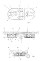
- the tape 1 consists of two mirror-symmetrical to each other Tabs which are designed as so-called band tabs 2 Band tabs 2 are pivotally connected to each other by a band eye 4 and arranged so that the wing 5 up to one Opening angle of 180 ° can be opened.
- the tape 1 is preferably made of metallic materials.
- the band tabs 2 can be different Have external shapes, e.g. B. round or angular.
- Both that Side part 3 and the wing 5 consist mainly of glass in Form of so-called all-glass panes.
- the all-glass panes can e.g. B. be colored or profiled.
- the detailed explanation and representation is limited to the immediate area of a Volume 1 and the processes taking place there.
- Both band tabs 2 are each between a holding piece 6 and one Clamping element 7 can be clamped, the holding piece 6 being directly force and is positively glued to the corresponding glass element 3.
- Advantageously is on the holding piece 6 on the back of a groove, not shown designed to hold adhesive to prevent lateral leakage of the Avoid glue.
- the clamping element 7 is by means of fastening elements 8 in the form of Screwing through a recess 9 in the form of an elongated hole Hinge flap 2 connected to the holding piece 6 to the hinge flap 2 to fix by clamping.
- the holding piece 6 is plate-shaped and has a protruding approach 10 which is complementary with play in the trained recess 9 of the hinge tab 2 protrudes. Defined the game the adjustment range and the elongated extension of the Recess 9 or the approach 10 in the embodiment possible horizontal adjustment.
- the approach 10 is integrally formed on the holding piece 6.
- a 3 are two approaches 10 as individual parts executed, the form-fitting on the back of the Holding piece 6 have been used.
- the Hinge tab 2 with the recess 9 on the holding piece 6 or the approach 10 set are arranged on the holes 11 screws 8 in the Threaded bores 12 of the holding piece 6 screwed in. Due to the Floating storage of the band tab 2 on the neck 10 of the holding piece 6 can the band tab 2 before the final tightening of the Screws 8 can be adjusted horizontally. The exact positioning takes place by the clamping screwing of the hinge tab 2 between the Clamping element 7 and the holding piece 6.
- the screws 8 are sunk in the holes 11 during a the countersunk surface 13 surrounding the boreholes 11 is flush-fitted a cover 14 allows.
- the clamping element 7 preferably has Side walls 15 so that the band tab 2 are topped can.
- an additional or alternative cover 16 crown at least the clamping element 7 and the band tab 2.
- FIGS. 4 to 6 show fittings 1 by means of which a glass element 5 can be rigidly attached to a stationary element 3.
- a glass element 5 can be rigidly attached to a stationary element 3.
- the fittings 1 exist in each case from a tab 2 and an integrally formed and angled thereon Mounting plate 17.
- the mounting plate 17 is attached to the room wall 3 and, depending on the version, does not point closer described devices for fine adjustment.
- the tab 2 is in the above-described manner between the holding piece 6 and one Clamping element 7 clamped.
- an approach 10 is formed as a separate component, the before the holding piece 6 is glued to the glass element 5 in a form-fitting manner is inserted into the holding piece 6.
- the approach 10 protrudes into the Recess 9 of the tab 2.
- a fastener 8 screwed in to finally fix the tab 2 in position.
- the fastening element 8 is sunk into the borehole 11 at the front and finally a cover 16 over the clamping element 7, the tab 2 and the holding piece 6 slipped.
- a projection 10 is integrally formed on the holding piece 6.
- the approach 10 protrudes into the recess 9 of the tab 2 and points additionally a protruding and non-rotatably arranged fastener 8 on.
- a threaded blind hole 12 is in the clamping element 7 formed so that the clamping element 7 with the interposition of the tab 2 attached to the holding piece 6 and ultimately the tab 2 in position can be fixed.
- the clamping element 7 has handling devices on the front 18 in the form of inlets in which suitable Tool for rotating the clamping element 7 can intervene.
- the holding piece 6 is plate-shaped and has additionally a protruding and non-rotatably arranged fastener 8 on.
- a projection 10 is formed in one piece on the clamping element 7, which protrudes into the recess 9 of the tab 2.
- points Clamping element 7 has a threaded bore 12 so that the clamping element 7 attached to the holding piece 6 with the interposition of the tab 2 and ultimately the tab 2 can be fixed in position.
- the clamping element 7 has handling devices 18 in the form of Inlets in the suitable tool for turning the clamping element 7 can intervene.
- a hood-shaped cover 16 attached to the clamping element 7.
Landscapes
- Engineering & Computer Science (AREA)
- Mechanical Engineering (AREA)
- Health & Medical Sciences (AREA)
- Public Health (AREA)
- Epidemiology (AREA)
- General Health & Medical Sciences (AREA)
- Securing Of Glass Panes Or The Like (AREA)
- Hinges (AREA)
- Piezo-Electric Or Mechanical Vibrators, Or Delay Or Filter Circuits (AREA)
- Details Of Aerials (AREA)
Abstract
Description
- Figur 1:
- Eine Ansicht auf ein Band.
- Figur 2:
- Einen Querschnitt des Bandes gemäß Figur 1 im montierten Zustand.
- Figur 3:
- Einen Querschnitt eines alternativ ausgeführten Bandlappens.
- Figur 4:
- Einen Querschnitt durch einen Beschlag, mit dem ein Glaselement an einem stationären Element befestigt wird.
- Figur 5:
- Einen Querschnitt durch einen alternativen Beschlag mit dem ein Glaselement an einem stationären Element befestigt wird.
- Figur 6:
- Einen Querschnitt durch einen weiteren alternativen Beschlag mit dem ein Glaselement an einem stationären Element befestigt wird.
- 1
- Beschlag, Band
- 2
- Lasche, Bandlappen
- 3
- benachbartes Element, Seitenteil
- 4
- Bandauge
- 5
- Glaselement, Flügel
- 6
- Haltestück
- 7
- Klemmelement
- 8
- Befestigungselement
- 9
- Ausnehmung
- 10
- Ansatz
- 11
- Bohrloch
- 12
- Gewindebohrung
- 13
- Senkfläche
- 14
- Deckel
- 15
- Seitenwand
- 16
- Abdeckung
- 17
- Montageplatte
- 18
- Handhabungseinrichtung, Einlaß
Claims (12)
- Justierbarer Beschlag für die Befestigung eines Glaselementes (5) an einem benachbarten Element (3), wobei an dem Glaselement (5) außenseitig ein Haltestück (6) kraft- und formschlüssig verklebt ist und wobei eine Lasche (2) des Beschlages (1) jeweils zwischen einem Klemmelement (7) und dem Haltestück (6) justierbar verspannt ist.
- Justierbarer Beschlag nach Anspruch 1, dadurch gekennzeichnet, daß in der Lasche (2) eine Ausnehmung (9) vorhanden ist, in die zumindest ein an dem Haltestück (6) oder an dem Klemmelement (7) ausgebildeter Ansatz (10) mit Spiel eingreift.
- Justierbarer Beschlag nach Anspruch 2, dadurch gekennzeichnet, daß die Ausnehmung (9) als Langloch ausgebildet ist.
- Justierbarer Beschlag nach Anspruch 2 oder 3, dadurch gekennzeichnet, daß der Ansatz (10) separat ausgebildet ist.
- Justierbarer Beschlag nach einem der Ansprüche 2 bis 4, dadurch gekennzeichnet, daß in dem Haltestück (6) oder dem Ansatz (10) Gewindebohrungen (12) und in dem Klemmelement (7) Bohrlöcher (11) ausgebildet sind, in die Befestigungselemente (8) einführbar sind.
- Justierbarer Beschlag nach Anspruch 5, dadurch gekennzeichnet, daß die Befestigungselemente (8) in dem Klemmelement (7) versenkbar und flächenbündig abdeckbar sind.
- Justierbarer Beschlag nach einem der Ansprüche 2 bis 4, dadurch gekennzeichnet, daß an dem Haltestück (6) oder dem Ansatz (10) Befestigungselemente (8) befestigt sind, die mit Gewindebohrungen (12) des Klemmelementes (7) zusammenwirken.
- Justierbarer Beschlag nach Anspruch 7, dadurch gekennzeichnet, daß das Klemmelement (7) Handhabungseinrichtungen (18) aufweist.
- Justierbarer Beschlag nach einem der Ansprüche 1 bis 8, dadurch gekennzeichnet, daß das Klemmelement (7) Seitenwände (15) aufweist, die zumindest die Lasche (2) überkronen.
- Justierbarer Beschlag nach einem der Ansprüche 1 bis 9, dadurch gekennzeichnet, daß eine Abdeckung (16) zumindest das Klemmelement (7) überkront.
- Justierbarer Beschlag nach einem der Ansprüche 1 bis 10, dadurch gekennzeichnet, daß an der Lasche (2) eine abgewinkelte Montageplatte (17) ausgebildet ist.
- Justierbarer Beschlag nach einem der Ansprüche 1 bis 10, dadurch gekennzeichnet, daß die Lasche als Bandlappen (2) ausgebildet ist, der gelenkig mit einem weiteren Bandlappen (2) verbunden ist.
Applications Claiming Priority (2)
| Application Number | Priority Date | Filing Date | Title |
|---|---|---|---|
| DE19960722A DE19960722C2 (de) | 1999-12-16 | 1999-12-16 | Justierbarer Beschlag |
| DE19960722 | 1999-12-16 |
Publications (3)
| Publication Number | Publication Date |
|---|---|
| EP1108843A2 true EP1108843A2 (de) | 2001-06-20 |
| EP1108843A3 EP1108843A3 (de) | 2001-10-17 |
| EP1108843B1 EP1108843B1 (de) | 2006-04-05 |
Family
ID=7932906
Family Applications (1)
| Application Number | Title | Priority Date | Filing Date |
|---|---|---|---|
| EP00127492A Expired - Lifetime EP1108843B1 (de) | 1999-12-16 | 2000-12-14 | Glaselement mit justierbarem Beschlag |
Country Status (3)
| Country | Link |
|---|---|
| EP (1) | EP1108843B1 (de) |
| AT (1) | ATE322599T1 (de) |
| DE (2) | DE19960722C2 (de) |
Cited By (12)
| Publication number | Priority date | Publication date | Assignee | Title |
|---|---|---|---|---|
| ES2211263A1 (es) * | 2001-12-21 | 2004-07-01 | Kemen Mobiliario Y Organizacion De Oficinas, S.L. | Dispositivo de montaje para bisagras de puertas de cristal en mobiliario-. |
| WO2004083579A1 (de) * | 2003-03-21 | 2004-09-30 | Reichel Guenter | Beschlag |
| EP1510163A3 (de) * | 2003-08-26 | 2005-06-29 | Cadenas, Irene Alonso | Duschabtrennung mit Glasscheibe und Beschlag für die Glasscheibe |
| EP1319359A3 (de) * | 2001-12-13 | 2006-02-08 | Duka S.r.l. | Tür für eine Duschkabine |
| EP1679409A1 (de) * | 2004-12-21 | 2006-07-12 | Geberit Technik Ag | Vorrichtung zur Befestigung eines Sanitärartikels |
| EP1589172A3 (de) * | 2004-04-20 | 2008-11-19 | DORMA GmbH + Co. KG | Band |
| RU2342511C2 (ru) * | 2002-10-28 | 2008-12-27 | Инхан Техтаат Ой Аб | Петля и способ ее изготовления |
| EP2037070A1 (de) * | 2007-09-15 | 2009-03-18 | Simonswerk, Gesellschaft mit beschränkter Haftung | Tür, insbesondere stumpf anschlagende Tür |
| DE202009002985U1 (de) * | 2009-03-05 | 2010-04-29 | Altura Leiden Holding B.V. | Scharniersystem für Trennwände |
| EP2492424A3 (de) * | 2011-02-23 | 2014-10-08 | Altura Leiden Holding B.V. | Verbindungsvorrichtung einer Trennwand, insbesondere Duschtrennwand |
| EP2636956B1 (de) * | 2012-03-06 | 2017-12-13 | Electrolux Home Products Corporation N.V. | Ofentür für einen Herd, und Verfahren zur Herstellung einer Ofentür für einen Herd |
| US20170355218A1 (en) * | 2016-06-13 | 2017-12-14 | Pr Germany Gmbh | Glass Element For Shower Cubicle |
Families Citing this family (4)
| Publication number | Priority date | Publication date | Assignee | Title |
|---|---|---|---|---|
| DE10212013A1 (de) * | 2002-03-18 | 2003-10-02 | Artweger Gmbh & Co | Glasbauteil |
| DE10218873B4 (de) † | 2002-04-26 | 2004-02-26 | Dorma Gmbh + Co. Kg | Lasche |
| DE102005019454B3 (de) * | 2005-04-25 | 2006-09-28 | Hellglas Duschen Gmbh | Scharnierelement für rahmenlose Glastüren |
| DE102010030814A1 (de) * | 2010-07-01 | 2012-01-05 | Bayerische Motoren Werke Aktiengesellschaft | Einrichtung zur lagegenauen Befestigung eines Montageteiles an einem Wandbereich |
Citations (1)
| Publication number | Priority date | Publication date | Assignee | Title |
|---|---|---|---|---|
| EP0875649A2 (de) | 1997-04-28 | 1998-11-04 | Novoferm Produktions- und Vertriebsgesellschaft m.b.H. | Zarge für feuerhemmende bzw. feuerbeständige Brandschutztüren |
Family Cites Families (6)
| Publication number | Priority date | Publication date | Assignee | Title |
|---|---|---|---|---|
| DE7705090U1 (de) * | 1977-02-19 | 1977-06-16 | Bfg Glassgroup, Paris | Klemmbeschlag fuer ganzglasanlagen |
| DE3630234C2 (de) * | 1986-09-05 | 1994-04-28 | Simonswerk Gmbh | Vorrichtung zur Befestigung eines Tür- oder Fensterbandes |
| DE3805095A1 (de) * | 1988-02-18 | 1989-08-31 | Casma Spa | Tuer oder fenster mit verstellbarem scharnier |
| DE29516023U1 (de) * | 1995-10-10 | 1997-02-06 | Pauli + Sohn GmbH, 51545 Waldbröl | Beschlag |
| DE19614307A1 (de) * | 1996-04-11 | 1997-10-16 | Hunsruecker Glasveredelung Wag | Einseitig flache Glashalterung |
| DE19945184A1 (de) * | 1999-09-21 | 2001-04-12 | Fischbach Joachim | Befestigungsvorrichtung für plattenförmige Bauteile |
-
1999
- 1999-12-16 DE DE19960722A patent/DE19960722C2/de not_active Expired - Fee Related
-
2000
- 2000-12-14 DE DE50012522T patent/DE50012522D1/de not_active Expired - Lifetime
- 2000-12-14 AT AT00127492T patent/ATE322599T1/de active
- 2000-12-14 EP EP00127492A patent/EP1108843B1/de not_active Expired - Lifetime
Patent Citations (1)
| Publication number | Priority date | Publication date | Assignee | Title |
|---|---|---|---|---|
| EP0875649A2 (de) | 1997-04-28 | 1998-11-04 | Novoferm Produktions- und Vertriebsgesellschaft m.b.H. | Zarge für feuerhemmende bzw. feuerbeständige Brandschutztüren |
Cited By (15)
| Publication number | Priority date | Publication date | Assignee | Title |
|---|---|---|---|---|
| EP1319359A3 (de) * | 2001-12-13 | 2006-02-08 | Duka S.r.l. | Tür für eine Duschkabine |
| ES2211263A1 (es) * | 2001-12-21 | 2004-07-01 | Kemen Mobiliario Y Organizacion De Oficinas, S.L. | Dispositivo de montaje para bisagras de puertas de cristal en mobiliario-. |
| RU2342511C2 (ru) * | 2002-10-28 | 2008-12-27 | Инхан Техтаат Ой Аб | Петля и способ ее изготовления |
| WO2004083579A1 (de) * | 2003-03-21 | 2004-09-30 | Reichel Guenter | Beschlag |
| AU2004221739B2 (en) * | 2003-03-21 | 2009-08-20 | Gunter Reichel | Fitting |
| EP1510163A3 (de) * | 2003-08-26 | 2005-06-29 | Cadenas, Irene Alonso | Duschabtrennung mit Glasscheibe und Beschlag für die Glasscheibe |
| EP1589172A3 (de) * | 2004-04-20 | 2008-11-19 | DORMA GmbH + Co. KG | Band |
| EP1679409A1 (de) * | 2004-12-21 | 2006-07-12 | Geberit Technik Ag | Vorrichtung zur Befestigung eines Sanitärartikels |
| EP2037070A1 (de) * | 2007-09-15 | 2009-03-18 | Simonswerk, Gesellschaft mit beschränkter Haftung | Tür, insbesondere stumpf anschlagende Tür |
| DE202009002985U1 (de) * | 2009-03-05 | 2010-04-29 | Altura Leiden Holding B.V. | Scharniersystem für Trennwände |
| EP2225987A2 (de) | 2009-03-05 | 2010-09-08 | Altura Leiden Holding B.V. | Scharniersystem für Trennwände und Verfahren zur Ausrüstung eines Scharniersystems |
| EP2225987A3 (de) * | 2009-03-05 | 2017-03-08 | Altura Leiden Holding B.V. | Scharniersystem für Trennwände und Verfahren zur Ausrüstung eines Scharniersystems |
| EP2492424A3 (de) * | 2011-02-23 | 2014-10-08 | Altura Leiden Holding B.V. | Verbindungsvorrichtung einer Trennwand, insbesondere Duschtrennwand |
| EP2636956B1 (de) * | 2012-03-06 | 2017-12-13 | Electrolux Home Products Corporation N.V. | Ofentür für einen Herd, und Verfahren zur Herstellung einer Ofentür für einen Herd |
| US20170355218A1 (en) * | 2016-06-13 | 2017-12-14 | Pr Germany Gmbh | Glass Element For Shower Cubicle |
Also Published As
| Publication number | Publication date |
|---|---|
| ATE322599T1 (de) | 2006-04-15 |
| DE19960722C2 (de) | 2002-08-01 |
| DE19960722A1 (de) | 2001-06-28 |
| EP1108843B1 (de) | 2006-04-05 |
| DE50012522D1 (de) | 2006-05-18 |
| EP1108843A3 (de) | 2001-10-17 |
Similar Documents
| Publication | Publication Date | Title |
|---|---|---|
| EP1108843B1 (de) | Glaselement mit justierbarem Beschlag | |
| EP2369107B1 (de) | Band, insbesondere für Kunststofftüren und Kunststofffenster | |
| DE29514335U1 (de) | Stahlzargen-Scharnierkonstruktion | |
| DE102005022042B3 (de) | Mehrdimensional verstellbares Türband an einem Türflügel | |
| DE3511493A1 (de) | Moebelscharnier | |
| DE19960721C2 (de) | Justierbares Band | |
| DE19949057C2 (de) | Befestigungsvorrichtung für eine Duschabtrennung | |
| EP1108840B1 (de) | Justierbarer Beschlag | |
| EP1108841B1 (de) | Justierbares Band | |
| EP1108842B1 (de) | Justierbares Band | |
| DE19960720C2 (de) | Justierbares Band | |
| DE19960719C2 (de) | Justierbares Band | |
| AT397410B (de) | Zargenverkleidung | |
| DE10049244C2 (de) | Band | |
| EP1457629B1 (de) | Vorrichtung zur Befestigung und/oder drehbeweglichen Verbindung von Tür- und/oder Wandelementen | |
| DE102007025857A1 (de) | Gelenkband für Türen oder Fenster | |
| DE10301054B3 (de) | Scharnier | |
| DE10023762C2 (de) | Beschlag für einen Glasflügel | |
| DE10210478C1 (de) | Band | |
| EP2225987B1 (de) | Scharniersystem für Trennwände und Verfahren zur Ausrüstung eines Scharniersystems | |
| DE102005019454B3 (de) | Scharnierelement für rahmenlose Glastüren | |
| DE102006030783B4 (de) | Rahmenlose Trennwand, mit einem Oberlicht und mit einem justierbaren Montageprofil zur Montage an einer ortsfesten Zarge | |
| DE10149810B4 (de) | Anordnung eines gefälzten Türblattes an einer Zarge | |
| DE29602431U1 (de) | Verstellbare Türzarge | |
| DE102005050652A1 (de) | Verfahren zur Verkleidung einer Stahlzange |
Legal Events
| Date | Code | Title | Description |
|---|---|---|---|
| PUAI | Public reference made under article 153(3) epc to a published international application that has entered the european phase |
Free format text: ORIGINAL CODE: 0009012 |
|
| AK | Designated contracting states |
Kind code of ref document: A2 Designated state(s): AT BE CH CY DE DK ES FI FR GB GR IE IT LI LU MC NL PT SE TR |
|
| AX | Request for extension of the european patent |
Free format text: AL;LT;LV;MK;RO;SI |
|
| RIN1 | Information on inventor provided before grant (corrected) |
Inventor name: KIRSCHKE, JACQUELINE Inventor name: LUEMKEMANN, ROLF Inventor name: PETER, MARTIN |
|
| PUAL | Search report despatched |
Free format text: ORIGINAL CODE: 0009013 |
|
| AK | Designated contracting states |
Kind code of ref document: A3 Designated state(s): AT BE CH CY DE DK ES FI FR GB GR IE IT LI LU MC NL PT SE TR |
|
| AX | Request for extension of the european patent |
Free format text: AL;LT;LV;MK;RO;SI |
|
| 17P | Request for examination filed |
Effective date: 20020417 |
|
| AKX | Designation fees paid |
Free format text: AT BE CH CY DE DK ES FI FR GB GR IE IT LI LU MC NL PT SE TR |
|
| 17Q | First examination report despatched |
Effective date: 20020703 |
|
| GRAP | Despatch of communication of intention to grant a patent |
Free format text: ORIGINAL CODE: EPIDOSNIGR1 |
|
| RTI1 | Title (correction) |
Free format text: GLASS PANEL WITH ADJUSTABLE HINGE |
|
| GRAS | Grant fee paid |
Free format text: ORIGINAL CODE: EPIDOSNIGR3 |
|
| GRAA | (expected) grant |
Free format text: ORIGINAL CODE: 0009210 |
|
| AK | Designated contracting states |
Kind code of ref document: B1 Designated state(s): AT BE CH CY DE DK ES FI FR GB GR IE IT LI LU MC NL PT SE TR |
|
| PG25 | Lapsed in a contracting state [announced via postgrant information from national office to epo] |
Ref country code: IT Free format text: LAPSE BECAUSE OF FAILURE TO SUBMIT A TRANSLATION OF THE DESCRIPTION OR TO PAY THE FEE WITHIN THE PRESCRIBED TIME-LIMIT;WARNING: LAPSES OF ITALIAN PATENTS WITH EFFECTIVE DATE BEFORE 2007 MAY HAVE OCCURRED AT ANY TIME BEFORE 2007. THE CORRECT EFFECTIVE DATE MAY BE DIFFERENT FROM THE ONE RECORDED. Effective date: 20060405 Ref country code: IE Free format text: LAPSE BECAUSE OF FAILURE TO SUBMIT A TRANSLATION OF THE DESCRIPTION OR TO PAY THE FEE WITHIN THE PRESCRIBED TIME-LIMIT Effective date: 20060405 Ref country code: FI Free format text: LAPSE BECAUSE OF FAILURE TO SUBMIT A TRANSLATION OF THE DESCRIPTION OR TO PAY THE FEE WITHIN THE PRESCRIBED TIME-LIMIT Effective date: 20060405 Ref country code: GB Free format text: LAPSE BECAUSE OF FAILURE TO SUBMIT A TRANSLATION OF THE DESCRIPTION OR TO PAY THE FEE WITHIN THE PRESCRIBED TIME-LIMIT Effective date: 20060405 |
|
| REG | Reference to a national code |
Ref country code: GB Ref legal event code: FG4D Free format text: NOT ENGLISH |
|
| REG | Reference to a national code |
Ref country code: CH Ref legal event code: EP |
|
| REG | Reference to a national code |
Ref country code: IE Ref legal event code: FG4D Free format text: LANGUAGE OF EP DOCUMENT: GERMAN |
|
| REF | Corresponds to: |
Ref document number: 50012522 Country of ref document: DE Date of ref document: 20060518 Kind code of ref document: P |
|
| PG25 | Lapsed in a contracting state [announced via postgrant information from national office to epo] |
Ref country code: SE Free format text: LAPSE BECAUSE OF FAILURE TO SUBMIT A TRANSLATION OF THE DESCRIPTION OR TO PAY THE FEE WITHIN THE PRESCRIBED TIME-LIMIT Effective date: 20060705 Ref country code: DK Free format text: LAPSE BECAUSE OF FAILURE TO SUBMIT A TRANSLATION OF THE DESCRIPTION OR TO PAY THE FEE WITHIN THE PRESCRIBED TIME-LIMIT Effective date: 20060705 |
|
| PG25 | Lapsed in a contracting state [announced via postgrant information from national office to epo] |
Ref country code: ES Free format text: LAPSE BECAUSE OF FAILURE TO SUBMIT A TRANSLATION OF THE DESCRIPTION OR TO PAY THE FEE WITHIN THE PRESCRIBED TIME-LIMIT Effective date: 20060716 |
|
| PG25 | Lapsed in a contracting state [announced via postgrant information from national office to epo] |
Ref country code: PT Free format text: LAPSE BECAUSE OF FAILURE TO SUBMIT A TRANSLATION OF THE DESCRIPTION OR TO PAY THE FEE WITHIN THE PRESCRIBED TIME-LIMIT Effective date: 20060905 |
|
| GBV | Gb: ep patent (uk) treated as always having been void in accordance with gb section 77(7)/1977 [no translation filed] |
Effective date: 20060405 |
|
| REG | Reference to a national code |
Ref country code: IE Ref legal event code: FD4D |
|
| PG25 | Lapsed in a contracting state [announced via postgrant information from national office to epo] |
Ref country code: LI Free format text: LAPSE BECAUSE OF NON-PAYMENT OF DUE FEES Effective date: 20061231 Ref country code: CH Free format text: LAPSE BECAUSE OF NON-PAYMENT OF DUE FEES Effective date: 20061231 Ref country code: MC Free format text: LAPSE BECAUSE OF NON-PAYMENT OF DUE FEES Effective date: 20061231 Ref country code: BE Free format text: LAPSE BECAUSE OF NON-PAYMENT OF DUE FEES Effective date: 20061231 |
|
| PLBE | No opposition filed within time limit |
Free format text: ORIGINAL CODE: 0009261 |
|
| STAA | Information on the status of an ep patent application or granted ep patent |
Free format text: STATUS: NO OPPOSITION FILED WITHIN TIME LIMIT |
|
| 26N | No opposition filed |
Effective date: 20070108 |
|
| EN | Fr: translation not filed | ||
| REG | Reference to a national code |
Ref country code: CH Ref legal event code: PL |
|
| BERE | Be: lapsed |
Owner name: DORMA G.M.B.H. + CO. KG Effective date: 20061231 |
|
| PG25 | Lapsed in a contracting state [announced via postgrant information from national office to epo] |
Ref country code: FR Free format text: LAPSE BECAUSE OF FAILURE TO SUBMIT A TRANSLATION OF THE DESCRIPTION OR TO PAY THE FEE WITHIN THE PRESCRIBED TIME-LIMIT Effective date: 20070309 Ref country code: GR Free format text: LAPSE BECAUSE OF FAILURE TO SUBMIT A TRANSLATION OF THE DESCRIPTION OR TO PAY THE FEE WITHIN THE PRESCRIBED TIME-LIMIT Effective date: 20060706 |
|
| PG25 | Lapsed in a contracting state [announced via postgrant information from national office to epo] |
Ref country code: TR Free format text: LAPSE BECAUSE OF FAILURE TO SUBMIT A TRANSLATION OF THE DESCRIPTION OR TO PAY THE FEE WITHIN THE PRESCRIBED TIME-LIMIT Effective date: 20060405 Ref country code: LU Free format text: LAPSE BECAUSE OF NON-PAYMENT OF DUE FEES Effective date: 20061214 |
|
| PG25 | Lapsed in a contracting state [announced via postgrant information from national office to epo] |
Ref country code: CY Free format text: LAPSE BECAUSE OF FAILURE TO SUBMIT A TRANSLATION OF THE DESCRIPTION OR TO PAY THE FEE WITHIN THE PRESCRIBED TIME-LIMIT Effective date: 20060405 Ref country code: FR Free format text: LAPSE BECAUSE OF FAILURE TO SUBMIT A TRANSLATION OF THE DESCRIPTION OR TO PAY THE FEE WITHIN THE PRESCRIBED TIME-LIMIT Effective date: 20060405 |
|
| PGFP | Annual fee paid to national office [announced via postgrant information from national office to epo] |
Ref country code: AT Payment date: 20131211 Year of fee payment: 14 Ref country code: DE Payment date: 20131220 Year of fee payment: 14 |
|
| PGFP | Annual fee paid to national office [announced via postgrant information from national office to epo] |
Ref country code: NL Payment date: 20131219 Year of fee payment: 14 |
|
| REG | Reference to a national code |
Ref country code: DE Ref legal event code: R081 Ref document number: 50012522 Country of ref document: DE Owner name: DORMA DEUTSCHLAND GMBH, DE Free format text: FORMER OWNER: DORMA GMBH + CO. KG, 58256 ENNEPETAL, DE Effective date: 20150224 |
|
| REG | Reference to a national code |
Ref country code: DE Ref legal event code: R119 Ref document number: 50012522 Country of ref document: DE |
|
| REG | Reference to a national code |
Ref country code: NL Ref legal event code: V1 Effective date: 20150701 |
|
| REG | Reference to a national code |
Ref country code: NL Ref legal event code: V1 Effective date: 20150701 |
|
| REG | Reference to a national code |
Ref country code: AT Ref legal event code: MM01 Ref document number: 322599 Country of ref document: AT Kind code of ref document: T Effective date: 20141214 |
|
| PG25 | Lapsed in a contracting state [announced via postgrant information from national office to epo] |
Ref country code: NL Free format text: LAPSE BECAUSE OF NON-PAYMENT OF DUE FEES Effective date: 20150701 |
|
| PG25 | Lapsed in a contracting state [announced via postgrant information from national office to epo] |
Ref country code: DE Free format text: LAPSE BECAUSE OF NON-PAYMENT OF DUE FEES Effective date: 20150701 |
|
| PG25 | Lapsed in a contracting state [announced via postgrant information from national office to epo] |
Ref country code: AT Free format text: LAPSE BECAUSE OF NON-PAYMENT OF DUE FEES Effective date: 20141214 |