EP1108608B1 - Vorrichtung zum Festklammern an eine Schiene - Google Patents
Vorrichtung zum Festklammern an eine Schiene Download PDFInfo
- Publication number
- EP1108608B1 EP1108608B1 EP20000403445 EP00403445A EP1108608B1 EP 1108608 B1 EP1108608 B1 EP 1108608B1 EP 20000403445 EP20000403445 EP 20000403445 EP 00403445 A EP00403445 A EP 00403445A EP 1108608 B1 EP1108608 B1 EP 1108608B1
- Authority
- EP
- European Patent Office
- Prior art keywords
- rail
- bolt part
- bolt
- clamping element
- channel
- Prior art date
- Legal status (The legal status is an assumption and is not a legal conclusion. Google has not performed a legal analysis and makes no representation as to the accuracy of the status listed.)
- Expired - Lifetime
Links
Images

Classifications
-
- B—PERFORMING OPERATIONS; TRANSPORTING
- B60—VEHICLES IN GENERAL
- B60P—VEHICLES ADAPTED FOR LOAD TRANSPORTATION OR TO TRANSPORT, TO CARRY, OR TO COMPRISE SPECIAL LOADS OR OBJECTS
- B60P7/00—Securing or covering of load on vehicles
- B60P7/06—Securing of load
- B60P7/08—Securing to the vehicle floor or sides
- B60P7/0807—Attachment points
- B60P7/0815—Attachment rails or trellis
Definitions
- the present invention relates to a rail attachment device, of the type allowing the attachment of straps or loads at selected locations among a plurality of predetermined locations along a rail.
- Rails are arranged from place to place on the walls, and straps can be hung at predetermined locations of the rails to allow the stowage of the cargo.
- the movable gripping element can be introduced into the channel only by one end thereof, the latch portion having a cross section substantially complementary to said channel.
- the wings of the rail leave between them a longitudinal opening with parallel edges in which the notches form lateral notches which define housing for said positioning element which is located outside the channel of the rail.
- the position of the engaging member may be varied by removing said locating member from its slot in the indentations, sliding the latch portion into the channel, and returning said locating member to a new housing.
- the attachment element is however prisoner of the canal by the part of lock and we can not introduce on the rail a new mobile attachment element without moving all those who precede the rail.
- the object of the invention is to remedy this problem and more generally to provide a new attachment device of the general type mentioned above, but improved in various aspects relating to the resistance of the attachment, to the ease of use. use, and to decrease noise during use.
- the invention achieves its purpose in the context of a hooking device of the aforementioned type by the characteristics of the characterizing part of claim 1.
- the lock is eclipsable and allows to introduce the attachment device at any point on the rail by the longitudinal opening of the channel between the rail flanges.
- Simply turn the latch tab by rotating the axis that protrudes from the channel to lock the device in the channel; the tab is pressed, by means of the spring, against the flange of the rail, from the inside to the outside, at a notch formed in the edge of the flange so as to lock the fastening device also longitudinally; in the predetermined position corresponding to the chosen notch.
- the lock portion has two opposite locking tabs so as to balance the device.
- the lock portion also comprises a cam portion allowing pivoting of the tab or lugs in one direction.
- the cam is constituted by a plate formed of two opposite circular quadrants and two opposed quadrants with non-circular profile of larger diameter.
- the latch portion may be integrally formed with the axle portion, or the latch portion and the axle portion may be disassociated. It can be secured to the assembly, allowing in particular the interposition of parts such as a holding flange of the hanging ring.
- the axle portion may also be slidably mounted in the latch portion. In this case, a spring is provided to maintain the axis portion in a stop position.
- the latch portion has under its lower face a compression spring, for example a helical spring, disposed between the web of the rail and said face.
- a compression spring for example a helical spring
- the compression spring can bear on the web of the rail via a cup.
- the cup is advantageously slidably mounted relative to the lock portion and retained by the head of a pin connected to the fastening element.
- a pin connected to the attachment element (which may be the same pin as that which holds the cup) allows the indexing of said element in holes provided in the rail at level of predetermined locations.
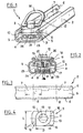
- the first embodiment of the device 1 of the invention illustrated in Figures 1 to 4, comprises a rail 2 in which is fixed a fastening element 3.
- the rail 2 is a profile of steel or aluminum obtained from rolling, substantially U-shaped having a core 4, two symmetrical wings 5 terminated at their upper part by a return 6 falling inwardly vertically, in which are formed in place, longitudinally, elongated notches 7. In the axis of the core 4, holes 8 are centered in the middle of the notches 7.
- the rail defines a longitudinal channel 9 with a longitudinal opening with parallel edges formed by returns 6.
- the fastening element 3 includes a lock portion having two opposite locking lugs 10 surmounted by a cam 11 and a central stud 12 constituting the axis of the fastening element.
- the tabs form a substantially rectangular plate with rounded corners, intended to engage in the notches 7 of the rail (the width L of the tabs 10 is at most substantially equal to or slightly less than the length L 'of the notches 7).
- the central pin 12 is traversed by a horizontal hole 13, rectilinear or curvilinear, to engage with possibility of articulation a portion of a gripping ring 14.
- An elastic element such as a Belleville washer 26 can be arranged between the upper face of the cam 11 and the gripping ring portion 24.
- the cam 11 is axially symmetrical and has a substantially diamond-shaped shape; it has a circular profile 15 on two opposite quadrants and a square profile 16 on the two opposite opposite quadrants; the smallest width D of the cam 11, equal to its diameter in the circular profile portion 15, is less than the opening of the rail 2 between its two flanges 6; on the other hand, the greatest width of the cam 11, corresponding to the diagonal of its square profile parts, is greater than said opening.
- the lower face of the fastening element 3 comprises an annular groove 17 surrounding an axial boss 18 pierced with a central thread 19 in which the threaded tail 20 of a pin 21 with a head 22 is screwed.
- the attachment element 3 is presented in front of the opening of the rail 2, between the two flanges 6, the locking lugs 10 being oriented parallel to the rail 2 so that the cup 23, the lugs 10 and the cam 11 can introducing into said opening, the cup 23 resting on the core 4 of the rail.
- the head 22 of the pilot pin encounters a hole 8 of the core and can penetrate therein, which defines a fastening location. If this location is the chosen location, then it suffices to rotate the attachment piece 3 by a quarter of a turn, in the only direction allowed by the cam 11, so as to place the locking tabs transversely in front of a latch. pair of notches 7. Then release the pressure on the ring 14 and the pin 12; the spring 25 pushes the lugs 10 in the notch 7 and thus holds the attachment piece.
- the spring 25 and the elastic washer 26 also contribute to reduce the loudness of the device.
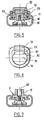
- Figures 5 and 6 show an alternative embodiment of the attachment piece in which the central pin 12 and the lower boss 18 are formed on a separate axis 30 which is engulfed in a central recess provided in the lock piece 35 in which are formed the locking tabs 10 and the cam 11.
- the shaft 30 forms a crimping cap having a gripping ridge 31 and a circular edge 32 for retaining an annular flange 33 whose edge comprises a hole 13 for the passage of a portion of the eccentric ring 14.
- the structure and operation of the device are identical to what has been indicated for the first embodiment.
- the attachment piece 3 has no ring 14 but in the upper pin 12, a central thread 40 for fixing various accessories.
- the ring 14 passes into a hole of an axis 50, which is slidably mounted vertically in a vertical bore of a latch piece 51 comprising two locking lugs 10.
- the axis 50 is retained under the lock piece 51 by a flange 52 pressing against a shoulder of said orifice, and it comprises a tapping 19 in which is screwed the threaded tail 20 of a pilot pin 21 whose rounded head 22 retains an end of a frustoconical compression spring 53 which is supported by its other end on the bottom 4 of the rail so as to permanently urge the axis 50 upwards.
- the locking tabs 10 are also urged upwards by a spring 25, supported on the one hand on the bottom 4 of the rail and on the other hand under the lock piece 51, where it is positioned by a circular rib 54 around said orifice.
- a curvilinear recess 55 is provided at the top of the latch piece 51 to allow the pin 50 to be driven into the bore, against the force of the spring 53, without being impeded by the ring 14, and to allow orient the locking tabs by operating the ring 14.
- the operation of the device is as follows.
- the axle By depressing the axis 50 vertically, the axle alone is first lowered and the head 22 of the pilot 21 which will be able to find the hole 8, the ring 14 being housed in the recess 55, then the axis carries with it the lock member 51 which can be oriented the legs 10 by turning the ring 14.
- the tabs found the notches of the rail edges, releasing the pressure on the axis 50; the spring 25 applies the locking tabs to the bottom of their notches and the spring 53 raises the shaft 50 in the up position, in which position it can freely rotate in the lock piece so as to present the ring 14 with the desired orientation.
- Figure 9 shows alternative embodiments of a rail 2.
- the holes 8 of the web 4 of the rail may be located on a raised central portion of the core forming a rib 4 '.
- the notches 7 of the flanges 6 of the rail whose width corresponds to the width of the locking tabs 10, may be surrounded on one side and / or on the other by an intermediate step 7 'allowing the locking tabs to be found. more easily the location of the notch 7.
Landscapes
- Engineering & Computer Science (AREA)
- Transportation (AREA)
- Mechanical Engineering (AREA)
- Clamps And Clips (AREA)
Claims (11)
- Vorrichtung zum Festklammern an einer Schiene, die Folgendes umfasst:- eine im Wesentlichen U-förmige Schiene (2), die einen Kanal (9) bildende Schenkel (5) und vorbestimmte Festklammerstellen definierende Kerben (7) aufweist,- ein bewegliches Festklammerelement (3), das einen Riegelteil (10, 11; 35; 51), der in den Kanal eingeführt werden und dort durch die Schenkel (5) der Schiene (2) gehalten werden kann, und einen im Wesentlichen senkrecht zur Schiene (2) verlaufenden, von dem Kanal (9) vorstehenden Achsteil (12; 30; 50), der Festklammermittel (14) trägt, aufweist,dadurch gekennzeichnet, dass- der Riegelteil (10, 11; 35; 51) ein Element zur Positionierung in Längsrichtung der Schiene (2) ist und unter elastischer Vorspannung in den Kerben (7) aufgenommen wird, um das Festklammerelement (3) an den vorbestimmten Stellen festzuhalten,- die Kerben (7) in herabhängenden Rändern (6) der Schenkel (5) der Schiene (2) ausgebildet sind,- der Riegel- und Positionierteil aus mindestens einem schwenkbaren Verriegelungsansatz (10) besteht, der sich im Inneren des Kanals (9) befindet, wenn das Festklammerelement (3) in Position ist, von dem Achsteil (12; 30; 50) aus betätigt werden kann und durch eine Feder (25) vorgespannt ist, um in einer der Kerben (7) der herabhängenden Ränder (6) der Schenkel (5) aufgenommen und verriegelt zu werden.
- Vorrichtung nach Anspruch 1, dadurch gekennzeichnet, dass der Riegelteil zwei einander gegenüberliegende Verriegelungsansätze (10) aufweist.
- Vorrichtung nach einem der vorhergehenden Ansprüche, dadurch gekennzeichnet, dass der Riegelteil des Weiteren einen Nockenteil (11) aufweist, der das Schwenken des Ansatzes (10) in eine einzige Richtung gestattet.
- Vorrichtung nach dem vorhergehenden Anspruch, dadurch gekennzeichnet, dass der Nocken (11) aus einer Platte besteht, die durch zwei kreisförmige, einander gegenüberliegende Quadranten und zwei nicht kreisförmige, einander gegenüberliegende Quadranten größeren Durchmessers gebildet wird.
- Vorrichtung nach einem der vorhergehenden Ansprüche, dadurch gekennzeichnet, dass der Riegelteil (10, 11) in einem Stück mit dem Achsteil (12) ausgebildet ist.
- Vorrichtung nach einem der Ansprüche 1 bis 4, dadurch gekennzeichnet, dass der Riegelteil (35; 51) und der Achsteil (30; 50) getrennt sind.
- Vorrichtung nach Anspruch 6, dadurch gekennzeichnet, dass der Achsteil (50) verschiebbar in dem Riegelteil (51) angebracht ist.
- Vorrichtung nach Anspruch 1, dadurch gekennzeichnet, dass der Riegelteil (10, 11; 35; 51) unter seiner Innenfläche eine Druckfeder (25) aufweist, die zwischen dem Steg der Schiene (2) und der Fläche angeordnet ist.
- Vorrichtung nach Anspruch 8, dadurch gekennzeichnet, dass die Druckfeder (25) durch einen Teller (23) am Steg der Schiene anliegt.
- Vorrichtung nach Anspruch 9, dadurch gekennzeichnet, dass der Teller (23) verschiebbar bezüglich des Riegelteils (10, 11) angebracht ist und durch den Kopf (22) eines mit dem Festklammerelement (3) verbundenen Zapfens (21) festgehalten wird.
- Vorrichtung nach einem der Ansprüche 1 - 9, dadurch gekennzeichnet, dass ein mit dem Festklammerelement (3) verbundener Zapfen (21) das Schalten des Festklammerelements (3) in den in der Schiene (2) an den vorbestimmten Stellen vorgesehenen Löchern (8) gestattet.
Applications Claiming Priority (2)
| Application Number | Priority Date | Filing Date | Title |
|---|---|---|---|
| FR9915685 | 1999-12-13 | ||
| FR9915685A FR2802254B1 (fr) | 1999-12-13 | 1999-12-13 | Dispositif d'accrochage a rail |
Publications (2)
| Publication Number | Publication Date |
|---|---|
| EP1108608A1 EP1108608A1 (de) | 2001-06-20 |
| EP1108608B1 true EP1108608B1 (de) | 2006-07-19 |
Family
ID=9553177
Family Applications (1)
| Application Number | Title | Priority Date | Filing Date |
|---|---|---|---|
| EP20000403445 Expired - Lifetime EP1108608B1 (de) | 1999-12-13 | 2000-12-08 | Vorrichtung zum Festklammern an eine Schiene |
Country Status (3)
| Country | Link |
|---|---|
| EP (1) | EP1108608B1 (de) |
| DE (1) | DE60029409T2 (de) |
| FR (1) | FR2802254B1 (de) |
Cited By (3)
| Publication number | Priority date | Publication date | Assignee | Title |
|---|---|---|---|---|
| EP1980446A1 (de) | 2007-04-13 | 2008-10-15 | BOS GmbH & Co. KG | Vorrichtung zum Befestigen von Ladegut in einem Transportmittel |
| US8915684B2 (en) | 2005-09-27 | 2014-12-23 | Fontaine Trailer Company, Inc. | Cargo deck |
| DE102019204386A1 (de) * | 2019-03-28 | 2020-10-01 | Kipp Gmbh & Co Kg | Befestigungssystem mit einer Lastschiene und einem Lastschlitten, insbesondere für einen Pick-Up-Truck |
Families Citing this family (20)
| Publication number | Priority date | Publication date | Assignee | Title |
|---|---|---|---|---|
| WO2001096144A1 (en) * | 2000-06-12 | 2001-12-20 | Southco, Inc. | Tie-down hoop |
| DE10149186B4 (de) * | 2001-10-05 | 2005-02-10 | Bayerische Motoren Werke Ag | Lastöse mit einer schienenförmigen Halterung für den Laderaum eines Kraftfahrzeuges |
| DE10325707A1 (de) * | 2003-06-06 | 2004-12-23 | Bayerische Motoren Werke Ag | Einrichtung zur Befestigung von Gegenständen, insbesondere in oder an einem Kraftfahrzeug |
| DE102005005346B4 (de) * | 2005-02-04 | 2008-09-18 | Schmitz Cargobull Ag | Verankerungssystem aus Ankerschiene und Gleitkörper |
| EP1733921B1 (de) * | 2005-06-17 | 2012-01-25 | Volvo Car Corporation | Lastensicherungselement |
| US8272819B1 (en) | 2009-06-23 | 2012-09-25 | Fontaine Trailer Company, Inc. | Restraining strap securement system |
| DE102006005559B4 (de) * | 2006-02-07 | 2007-11-29 | Manfred Berger | Befestigungssystem |
| DE102006033384A1 (de) | 2006-07-12 | 2008-01-17 | Bos Gmbh & Co. Kg | Laderaumfunktionsvorrichtung für ein Kraftfahrzeug |
| JP5221300B2 (ja) * | 2008-11-21 | 2013-06-26 | 株式会社パイオラックス | スライドロック装置 |
| US8807893B2 (en) | 2009-06-23 | 2014-08-19 | Fontaine Trailer Company, Inc. | Restraining strap securement system |
| CN103963975B (zh) * | 2013-01-29 | 2016-06-01 | 中国航空工业集团公司西安飞机设计研究所 | 一种可调间距式货盘限位装置 |
| FR3019115B1 (fr) * | 2014-03-27 | 2016-04-15 | A Raymond Et Cie | Dispositif d'accrochage a un rail |
| CN104290666B (zh) * | 2014-09-16 | 2016-08-24 | 浙江威世汽车配件有限公司 | 后备箱防护杆锁止机构 |
| CN105667801B (zh) * | 2014-11-19 | 2017-11-28 | 中国航空工业集团公司西安飞机设计研究所 | 一种航空集装板航向限动锁定机构 |
| DE102014225824B4 (de) * | 2014-12-15 | 2021-07-29 | Bos Gmbh & Co. Kg | Laderaum-Lastschienensystem für ein Kraftfahrzeug |
| CN105984368A (zh) * | 2015-02-15 | 2016-10-05 | 谢亚群 | 一种冷藏车厢内货物分层装载的支承杆 |
| CN106697072B (zh) * | 2016-12-25 | 2018-12-07 | 重庆鼎汉机械有限公司 | 一种后备箱档杆固定机构 |
| DE102017131132A1 (de) * | 2017-12-22 | 2019-06-27 | Airbus Operations Gmbh | Befestigungssystem zum Befestigen einer ersten Komponente in einem variablen Abstand an einer zweiten Komponente |
| CN207791700U (zh) * | 2017-12-27 | 2018-08-31 | 南通中集特种物流装备发展有限公司 | 货物挡杆结构及具有其的集装箱 |
| US10576868B1 (en) | 2018-11-07 | 2020-03-03 | Mashak Gilmour Company LLC | Cargo tie-down and a combination cargo tie-down and rail, and a method of securing the cargo tie-down to a rail |
Family Cites Families (7)
| Publication number | Priority date | Publication date | Assignee | Title |
|---|---|---|---|---|
| US2859710A (en) * | 1956-07-12 | 1958-11-11 | Aeroquip Corp | Rail-connected fitting |
| FR1161214A (fr) * | 1956-10-16 | 1958-08-25 | Aeroquip Corp | Dispositif pour l'arrimage de chargements sur des véhicules |
| US3713616A (en) * | 1971-03-05 | 1973-01-30 | T Bowers | Load holding device improvement |
| US4248558A (en) * | 1979-07-06 | 1981-02-03 | Lechner Ed F | Tie down anchor |
| GB2186018B (en) | 1986-01-29 | 1989-11-01 | Nissim Alfassa | Improvements in or relating to a stud fitting |
| FR2675442A1 (fr) * | 1991-04-18 | 1992-10-23 | Boni Sa | Dispositif permettant de mettre en place sans outillage des points de fixation pour le positionnement et l'ancrage solides d'une charge. |
| DE9105425U1 (de) | 1991-05-02 | 1991-10-02 | Ancra Jungfalk Gmbh, 7707 Engen, De |
-
1999
- 1999-12-13 FR FR9915685A patent/FR2802254B1/fr not_active Expired - Fee Related
-
2000
- 2000-12-08 DE DE2000629409 patent/DE60029409T2/de not_active Expired - Lifetime
- 2000-12-08 EP EP20000403445 patent/EP1108608B1/de not_active Expired - Lifetime
Cited By (5)
| Publication number | Priority date | Publication date | Assignee | Title |
|---|---|---|---|---|
| US8915684B2 (en) | 2005-09-27 | 2014-12-23 | Fontaine Trailer Company, Inc. | Cargo deck |
| EP1980446A1 (de) | 2007-04-13 | 2008-10-15 | BOS GmbH & Co. KG | Vorrichtung zum Befestigen von Ladegut in einem Transportmittel |
| DE102007018254A1 (de) | 2007-04-13 | 2008-10-16 | Bos Gmbh & Co. Kg | Vorrichtung zum Befestigen von Ladegut in einem Transportmittel |
| DE102019204386A1 (de) * | 2019-03-28 | 2020-10-01 | Kipp Gmbh & Co Kg | Befestigungssystem mit einer Lastschiene und einem Lastschlitten, insbesondere für einen Pick-Up-Truck |
| DE102019204386B4 (de) * | 2019-03-28 | 2021-02-04 | Kipp Gmbh & Co Kg | Befestigungssystem mit einer Lastschiene und einem Lastschlitten, insbesondere für einen Pick-Up-Truck |
Also Published As
| Publication number | Publication date |
|---|---|
| DE60029409D1 (de) | 2006-08-31 |
| FR2802254A1 (fr) | 2001-06-15 |
| FR2802254B1 (fr) | 2002-02-08 |
| EP1108608A1 (de) | 2001-06-20 |
| DE60029409T2 (de) | 2006-12-28 |
Similar Documents
| Publication | Publication Date | Title |
|---|---|---|
| EP1108608B1 (de) | Vorrichtung zum Festklammern an eine Schiene | |
| WO2000049299A1 (fr) | Dispositif de fixation de deux panneaux ou analogues forme de deux pieces cooperantes | |
| FR2958230A1 (fr) | Glissiere pour siege de vehicule et siege comportant une telle glissiere. | |
| EP1071887B1 (de) | Vorrichtung zum schnellen montieren und demontieren | |
| FR3041310A1 (fr) | Dispositif de confort, notamment pour vehicule ferroviaire, comprenant une table amovible perfectionnee | |
| EP1801323B1 (de) | Befestigungsvorrichtung eines Stabes auf einem Pfosten | |
| EP1978838B1 (de) | Ziehbares handgepäck mit einem gedämpften teleskopstiel | |
| EP0936128B1 (de) | Lenksystem, Lenkrad und Lenkradsäule für ein solches System | |
| EP0513105B1 (de) | Vorrichtung zur befestigung von eisenbahnschienen auf einem beton- oder metallträger | |
| EP2369186B1 (de) | Vierteldrehungs-Befestigungsvorrichtung | |
| EP0940326A1 (de) | Verschiebbarer Tragpfosten für Planendächer für Fahrzeugaufbauten | |
| WO2008122291A1 (fr) | Dispositif de fixation d'une lisse sur un poteau | |
| EP1000252A1 (de) | Sperrvorrichtung für eine tür eines kraftfahrzeuges | |
| EP3724000A1 (de) | Rolle für möbelstück | |
| FR2649138A1 (fr) | Dispositif de fixation elastique d'un rail de chemin de fer sur son support | |
| EP0501898B1 (de) | Kugelkopf-Anhängerkupplung | |
| EP0208582A1 (de) | Aufwickelspindel, insbesondere für einen Sicherheitsgurt | |
| EP4321384A1 (de) | Lastenträger für ein kraftfahrzeug | |
| EP0687819A2 (de) | Befestigungsvorrichtung für mindestens zwei Bauteile, z. B. Fahrzeugkarosserie | |
| FR2798429A1 (fr) | Collier de serrage a vis tangente | |
| WO2023062310A1 (fr) | Dispositif de fixation | |
| FR3041294A1 (fr) | Dispositif de verrouillage bi-positions d’un dossier de siege arriere de vehicule automobile. | |
| EP1647723B1 (de) | Rohrendstück, insbesondere für Leiter- oder Trittleiterholmen, und Montageverfahren | |
| FR2676786A1 (fr) | Dispositif d'assemblage pour tubes. | |
| FR2873905A1 (fr) | Support pour dispositif de stockage notamment de type cantilever |
Legal Events
| Date | Code | Title | Description |
|---|---|---|---|
| PUAI | Public reference made under article 153(3) epc to a published international application that has entered the european phase |
Free format text: ORIGINAL CODE: 0009012 |
|
| AK | Designated contracting states |
Kind code of ref document: A1 Designated state(s): BE DE ES GB IT |
|
| AX | Request for extension of the european patent |
Free format text: AL;LT;LV;MK;RO;SI |
|
| 17P | Request for examination filed |
Effective date: 20011206 |
|
| AKX | Designation fees paid |
Free format text: BE DE ES GB IT |
|
| RAP1 | Party data changed (applicant data changed or rights of an application transferred) |
Owner name: RENAULT S.A.S. |
|
| GRAP | Despatch of communication of intention to grant a patent |
Free format text: ORIGINAL CODE: EPIDOSNIGR1 |
|
| GRAS | Grant fee paid |
Free format text: ORIGINAL CODE: EPIDOSNIGR3 |
|
| GRAA | (expected) grant |
Free format text: ORIGINAL CODE: 0009210 |
|
| AK | Designated contracting states |
Kind code of ref document: B1 Designated state(s): BE DE ES GB IT |
|
| PG25 | Lapsed in a contracting state [announced via postgrant information from national office to epo] |
Ref country code: IT Free format text: LAPSE BECAUSE OF FAILURE TO SUBMIT A TRANSLATION OF THE DESCRIPTION OR TO PAY THE FEE WITHIN THE PRESCRIBED TIME-LIMIT;WARNING: LAPSES OF ITALIAN PATENTS WITH EFFECTIVE DATE BEFORE 2007 MAY HAVE OCCURRED AT ANY TIME BEFORE 2007. THE CORRECT EFFECTIVE DATE MAY BE DIFFERENT FROM THE ONE RECORDED. Effective date: 20060719 Ref country code: GB Free format text: LAPSE BECAUSE OF FAILURE TO SUBMIT A TRANSLATION OF THE DESCRIPTION OR TO PAY THE FEE WITHIN THE PRESCRIBED TIME-LIMIT Effective date: 20060719 |
|
| REG | Reference to a national code |
Ref country code: GB Ref legal event code: FG4D Free format text: NOT ENGLISH |
|
| REF | Corresponds to: |
Ref document number: 60029409 Country of ref document: DE Date of ref document: 20060831 Kind code of ref document: P |
|
| PG25 | Lapsed in a contracting state [announced via postgrant information from national office to epo] |
Ref country code: ES Free format text: LAPSE BECAUSE OF FAILURE TO SUBMIT A TRANSLATION OF THE DESCRIPTION OR TO PAY THE FEE WITHIN THE PRESCRIBED TIME-LIMIT Effective date: 20061030 |
|
| PG25 | Lapsed in a contracting state [announced via postgrant information from national office to epo] |
Ref country code: BE Free format text: LAPSE BECAUSE OF NON-PAYMENT OF DUE FEES Effective date: 20061231 |
|
| GBV | Gb: ep patent (uk) treated as always having been void in accordance with gb section 77(7)/1977 [no translation filed] |
Effective date: 20060719 |
|
| PLBE | No opposition filed within time limit |
Free format text: ORIGINAL CODE: 0009261 |
|
| STAA | Information on the status of an ep patent application or granted ep patent |
Free format text: STATUS: NO OPPOSITION FILED WITHIN TIME LIMIT |
|
| 26N | No opposition filed |
Effective date: 20070420 |
|
| BERE | Be: lapsed |
Owner name: RENAULT S.A.S. Effective date: 20061231 |
|
| PGFP | Annual fee paid to national office [announced via postgrant information from national office to epo] |
Ref country code: DE Payment date: 20161213 Year of fee payment: 17 |
|
| REG | Reference to a national code |
Ref country code: DE Ref legal event code: R119 Ref document number: 60029409 Country of ref document: DE |
|
| PG25 | Lapsed in a contracting state [announced via postgrant information from national office to epo] |
Ref country code: DE Free format text: LAPSE BECAUSE OF NON-PAYMENT OF DUE FEES Effective date: 20180703 |