EP0687819A2 - Befestigungsvorrichtung für mindestens zwei Bauteile, z. B. Fahrzeugkarosserie - Google Patents
Befestigungsvorrichtung für mindestens zwei Bauteile, z. B. Fahrzeugkarosserie Download PDFInfo
- Publication number
- EP0687819A2 EP0687819A2 EP95401149A EP95401149A EP0687819A2 EP 0687819 A2 EP0687819 A2 EP 0687819A2 EP 95401149 A EP95401149 A EP 95401149A EP 95401149 A EP95401149 A EP 95401149A EP 0687819 A2 EP0687819 A2 EP 0687819A2
- Authority
- EP
- European Patent Office
- Prior art keywords
- head
- elongated hole
- base
- locking member
- indexing means
- Prior art date
- Legal status (The legal status is an assumption and is not a legal conclusion. Google has not performed a legal analysis and makes no representation as to the accuracy of the status listed.)
- Granted
Links
- 230000006835 compression Effects 0.000 claims abstract description 9
- 238000007906 compression Methods 0.000 claims abstract description 9
- 230000000295 complement effect Effects 0.000 claims description 4
- 239000000463 material Substances 0.000 claims description 3
- 230000002093 peripheral effect Effects 0.000 claims description 3
- 238000005553 drilling Methods 0.000 abstract 1
- 230000000717 retained effect Effects 0.000 abstract 1
- 239000007787 solid Substances 0.000 abstract 1
- 230000035939 shock Effects 0.000 description 3
- 230000035882 stress Effects 0.000 description 3
- 238000004519 manufacturing process Methods 0.000 description 2
- 238000003466 welding Methods 0.000 description 2
- 230000006355 external stress Effects 0.000 description 1
- 239000002184 metal Substances 0.000 description 1
- 238000000465 moulding Methods 0.000 description 1
- 210000000056 organ Anatomy 0.000 description 1
- 238000010422 painting Methods 0.000 description 1
- 230000036316 preload Effects 0.000 description 1
- 230000000284 resting effect Effects 0.000 description 1
Images


Classifications
-
- F—MECHANICAL ENGINEERING; LIGHTING; HEATING; WEAPONS; BLASTING
- F16—ENGINEERING ELEMENTS AND UNITS; GENERAL MEASURES FOR PRODUCING AND MAINTAINING EFFECTIVE FUNCTIONING OF MACHINES OR INSTALLATIONS; THERMAL INSULATION IN GENERAL
- F16B—DEVICES FOR FASTENING OR SECURING CONSTRUCTIONAL ELEMENTS OR MACHINE PARTS TOGETHER, e.g. NAILS, BOLTS, CIRCLIPS, CLAMPS, CLIPS OR WEDGES; JOINTS OR JOINTING
- F16B5/00—Joining sheets or plates, e.g. panels, to one another or to strips or bars parallel to them
- F16B5/10—Joining sheets or plates, e.g. panels, to one another or to strips or bars parallel to them by means of bayonet connections
-
- B—PERFORMING OPERATIONS; TRANSPORTING
- B60—VEHICLES IN GENERAL
- B60R—VEHICLES, VEHICLE FITTINGS, OR VEHICLE PARTS, NOT OTHERWISE PROVIDED FOR
- B60R13/00—Elements for body-finishing, identifying, or decorating; Arrangements or adaptations for advertising purposes
- B60R13/02—Internal Trim mouldings ; Internal Ledges; Wall liners for passenger compartments; Roof liners
- B60R13/0206—Arrangements of fasteners and clips specially adapted for attaching inner vehicle liners or mouldings
-
- B—PERFORMING OPERATIONS; TRANSPORTING
- B62—LAND VEHICLES FOR TRAVELLING OTHERWISE THAN ON RAILS
- B62D—MOTOR VEHICLES; TRAILERS
- B62D27/00—Connections between superstructure or understructure sub-units
- B62D27/04—Connections between superstructure or understructure sub-units resilient
-
- B—PERFORMING OPERATIONS; TRANSPORTING
- B62—LAND VEHICLES FOR TRAVELLING OTHERWISE THAN ON RAILS
- B62D—MOTOR VEHICLES; TRAILERS
- B62D29/00—Superstructures, understructures, or sub-units thereof, characterised by the material thereof
- B62D29/04—Superstructures, understructures, or sub-units thereof, characterised by the material thereof predominantly of synthetic material
- B62D29/048—Connections therefor, e.g. joints
Definitions
- the present invention relates to a device for assembling at least two elements, for example of automobile bodywork.
- a device applies in particular to the fixing of a bumper on the bodywork or the chassis of a motor vehicle.
- the bodywork of a motor vehicle is generally made up of different elements of variable shapes and materials, which are generally assembled together by fixing devices of the screw-washer-nut type.
- the present invention therefore aims to eliminate the above drawbacks and to propose a device for assembling at least two elements, for example of automobile bodywork, allowing precise positioning of the latter relative to each other, which is easily mounted and dismountable and which ensures stable locking even in the presence of strong external stresses.
- the subject of the present invention is a device for assembling at least two adjacent elements, for example of automobile bodywork, the external surfaces of which are intended to bear against one another, of the type comprising a locking member consisting of a rod extending by a head extending substantially in a direction perpendicular to the rod, an elastic compression means bearing at one end on the internal surface of a first element to be assembled and whose l the other end is integral with the free end of said rod which passes axially through a bore formed through the wall of the first element and an elongated hole formed through the second element to be assembled, the elongated hole having a shape corresponding to the head of the locking member to allow the passage of said head through the second element in the unlocked position in which the head is aligned with the elongated hole, and indexing means formed on at least one of the elements to be assembled and intended to cooperate with the head of the member in the locked position in which the head bears transversely with respect to said hole elongated by the intermediate the main surface of its
- the locking member may advantageously have a general T shape, the leg and the bar of the T respectively forming the rod and the head of the member.
- the indexing means comprise in the longitudinal direction of the elongated hole surfaces for the reception of the main surface of the base in the unlocked position, said surfaces being housed inside the elongated hole of so that the head is partially engaged therein and located at an axially different level from its locked position where the compression generated by the elastic means is higher.
- the indexing means form part of a separate part adaptable through the first element, for example by welding or stapling.
- the first aforementioned element constitutes the separate part on which the indexing means are formed, said part coming to sandwich both a third element to be assembled and the aforementioned second element by means of a peripheral surface surrounding the base of the indexing means and coming to bear against the internal face of the third element which is pierced with an elongated opening corresponding to the above-mentioned elongated hole for the passage of the indexing means.
- the indexing means form an imprint of shape complementary to that of the base of the locking member, which ensures precise positioning of the various elements to be assembled.
- the aforementioned protrusions protrude from the internal surface of the second element to block the base in rotation in the locked position.
- the base of the head of the locking member may have a perfectly flat surface.
- the aforementioned base of the locking member comprises an axially raised portion relative to its main surface and intended to fit in the locked position between the protrusions which are preferably housed entirely in the elongated hole of the second element .
- the rod and the head of the locking member are made of different materials.
- the rod may for example be metallic so that it resists the stresses exerted by the compression spring and by the bodywork elements and the plastic head to avoid damaging the external appearance of the bodywork, for example to scratch the painting.
- the head of the locking member is pierced with an orifice intended to cooperate with a tool such as a hook used to selectively position the member in the locked or unlocked position, by axial traction .
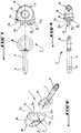
- Figure 1 is a perspective and exploded view of the assembly device of the present invention.
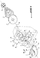
- Figure 2 is a schematic, partial and perspective view of a front bumper mounted on the body of a motor vehicle.
- FIG. 3 is a schematic perspective view of the device of the invention in the unlocked position, associated with an operating hook, according to arrow III in FIG. 2.
- Figure 4 is a view similar to that of Figure 3, but with the assembly device in the locked position.
- FIG. 5 is a schematic view in section of a variant of the device of the invention, along the line VV of FIG. 4.
- Figure 6 is a perspective and exploded view of the locking member of the device of the invention.
- FIG. 7 is an exploded view in longitudinal section of the locking member of FIG. 6.
- FIG. 8 is an exploded view in cross section of the locking member of FIG. 6.
- Figure 9 is a plan view of another variant of the device of Figure 1, along arrow IX, the locking member having been omitted.
- Figures 10 and 11 are broken sections with parallel planes of Figure 9, along the lines X-X and XI-XI, with the locking member in the locked and unlocked position respectively.
- the assembly device of the invention comprises a locking member 1, indexing means 2 and a compression spring 3.
- the spring 3 bears on one of its end turns on the internal surface 4a of a first body element such as a bumper skin 4, by means of a support washer 5 .
- the other end turn of the spring 3 is integral with a retaining washer 6 which adjusts around the free end of a rod 7, in a circular groove 8.
- the rod 7 passes axially through the spring 3, the support washer 5 and is extended at its other end by a substantially annular piece 9 forming the head of the locking member 1.
- the locking member 1 has a general T shape, the leg and the bar of the T respectively forming the rod 7 and the substantially annular part 9.
- the device of the invention is arranged to allow assembly of the bumper element 4 with another body element 10.
- the assembly of elements 4 and 10 is carried out by applying one against the other their facing or external surface 4b and 10b respectively.
- the head 9 of the locking member 1 is capable of coming to bear by its base 11 against the internal surface 10a of the bodywork element 10, so as to come to enclose the elements 4 and 10 between the head 9 of the locking member and spring 3.
- An elongated oblong hole 12 is formed through the second body element 10, the shape of the oblong hole 12 corresponding to the external contour of the base 11 of the head 9.
- the elongated hole 12 must be shaped so as to allow the passage of the head 9 of the locking member 1, when said head 9 is aligned with the elongated hole 12.
- the hole 12 can have any elongated shape, for example rectangular, elliptical or other.
- the elongated hole 12 defined in the direction of its length a longitudinal direction 13 and in the direction of its width a transverse direction 14 (see Figures 1 and 9).
- the rod 7 passes axially through a bore 15 (see FIG. 5) formed in the first bumper element 4 and which is coaxial with the axis 16 of the oblong hole 12.
- the rod 7 is separated from the head 9 by the base 11 forming a shoulder extending in a direction perpendicular to the axis of the rod 7.
- the base 11 has in its length a stepped surface consisting of a main surface 11a extending on either side of the rod 7 by two raised studs 11b adjacent to the rod 7.
- the base 11 of the head 9 also has in its width a stepped surface formed by the main surface 11a or the studs 11b which extend laterally by two underlying shoulders 11c.
- the indexing means 2 form an imprint of a shape complementary to that of the base 11 and formed projecting from the external surface 4b of the bumper element 4.
- the indexing means 2 can be hollowed out in the very thickness of the bodywork element 4.
- the underlying shoulders 11c and the raised studs 11b have substantially bevelled side walls to allow precise and automatic adjustment in the complementary imprint of the indexing means 2.
- the imprint 2 has a hollow or cross-shaped counterbore, centered on the bore 15 and consisting of two pairs 2a and 2c of diametrically opposite surfaces and oriented respectively in the longitudinal direction 13 and transverse 14 for the reception respectively of the main surface 11a and of the studs 11b in the respectively unlocked and locked position of the member 1, and four protrusions 2b formed projecting from the external face 4b of the first element 4, at the four corners of the hollow in the shape of a cross.
- the pair of surfaces 2a is extended, in the longitudinal direction 13, by another pair of surfaces 2d arranged on either side of the bore 15 and at a level below that of the surfaces 2a to receive the studs 11b in the unlocked position of organ 1.
- the head 9 of the locking member 1 is intended to be received between the two pairs of protrusions 2b located on either side of the axis 14 and the axis 13, when the locking member 1 is respectively in the locked or unlocked position.
- the imprint of the indexing means 2 has an axial symmetry with respect to the axis 16.
- the imprint 2 can be formed by molding during the manufacture of the bumper 4, or it can be part of a separate part 17 (shown in broken lines in Figure 1) adaptable through the first element 4, for example by welding or stapling.
- This separate part 17 can also be adapted to the first element 4 by a simple support as better represented in FIGS. 9 to 11.
- the part 17 plays the role here of the first element to be assembled and comprises for example a peripheral flange 17a intended to come resting against the external surface 4a of the first element 4 (acting here as the third element to be assembled) and surrounding the base of the cavity 2 which passes through an elongated bore (not shown) corresponding to this third element.
- the imprint 2 passes through both the third 4 and the second 10 elements to be assembled and the part 17 can be reused or replaced without having to change the body of the vehicle.
- the locking member 1 consists of two parts, the rod 7 being in one piece with a metal ring 18 which fits in an annular housing 19 provided internally in the plastic head 9 separate from rod 7.
- the head 9 can be provided for example in two symmetrical parts 9a, 9b (see FIG. 6) which come to fit around the ring 18 secured to the rod 7.
- the head 9 has a central orifice 20 for the passage, for example, of the end of an operating hook 21, illustrated in FIGS. 3 and 4.
- FIG. 2 shows an overall view of a bumper 4 of a motor vehicle fixed to a front structure 10 by means of the device of the invention indicated by arrow III.
- the head 9 of the locking member 1 is oriented in the longitudinal direction 13 of the oblong hole 12 of the body element 10, so that the 'The bumper 4 can be easily and quickly assembled or separated from the bodywork element 10 by approaching and moving the bumper element 4 away from the element 10 in the axial direction 16.
- This position of the locking member 1 is said to be unlocked and is shown in FIGS. 3 and 11.
- the main surface 11a, the studs 11b and the shoulder 11c of the base 11 rest respectively on the surfaces 2a and 2d of the hollow in the form of a cross and on the top of the protuberances 2b of the imprint 2.
- the head 9 is pulled in the direction of the arrow 22, that is to say in the axial direction 16, and it is rotated by a quarter of a turn as indicated. by the arrow 23 ( Figure 3), using for example the hook 21, so that the head 9 comes to align with the transverse direction 14 above.
- the head 9 is then released against the internal surface 10a of the second element 10, as indicated by the arrow 24 (FIG. 4). It is necessary to pull and release the head 9 in the direction of the axis 16 because in the unlocked position the head 9 is partially engaged in the opening 12.
- the head 9 moves away from the bumper element 4 by a distance equal to the difference in level between the surfaces 2a of the imprint and the internal face 10a of the second element 10 in the assembled position, for example of the order of the thickness of the bodywork element 10, which generates additional compression of the spring 3 in the locked position which adds to the initial preload of the spring 3, in the unlocked position .
- the elements 4 and 10 are assembled by an elastic means 3 preferably having a very high stiffness making it possible to compensate and to collect any shocks in the axial direction 16, to avoid any untimely dislocation of the studs 11b between the protuberances 2b in locked position.
- protuberances 2b project from the internal surface 10a of the second element 10, but these protuberances can alternatively be completely retracted in the oblong hole 12, as visible in FIGS. 10 and 11, the essential point being that these protrusions prevent the rotation of the locking member from its locked position to its unlocked position, unless first exerting axial traction on this member in order to disengage the base 11 from its housing defined between the protrusions 2b and surfaces 2c.
- the device of the invention has the function of ensuring a stable locking of the elements 4 and 10 together, even in the presence of vibrations or significant shocks, while allowing a simple and rapid unlocking for the replacement of the one of these.
- the shape of the base 11 can be modified without departing from the scope of the present invention and for example have a perfectly flat surface, in the case for example where the protuberances 2b protrude from the second element 10.
Applications Claiming Priority (2)
| Application Number | Priority Date | Filing Date | Title |
|---|---|---|---|
| FR9406131A FR2720126B1 (fr) | 1994-05-19 | 1994-05-19 | Dispositif d'assemblage d'au moins deux éléments par exemple de carrosserie automobile. |
| FR9406131 | 1994-05-19 |
Publications (3)
| Publication Number | Publication Date |
|---|---|
| EP0687819A2 true EP0687819A2 (de) | 1995-12-20 |
| EP0687819A3 EP0687819A3 (de) | 1996-12-18 |
| EP0687819B1 EP0687819B1 (de) | 2002-09-18 |
Family
ID=9463355
Family Applications (1)
| Application Number | Title | Priority Date | Filing Date |
|---|---|---|---|
| EP19950401149 Expired - Lifetime EP0687819B1 (de) | 1994-05-19 | 1995-05-17 | Befestigungsvorrichtung für mindestens zwei Bauteile, z. B. Fahrzeugkarosserie |
Country Status (4)
| Country | Link |
|---|---|
| EP (1) | EP0687819B1 (de) |
| DE (1) | DE69528215T2 (de) |
| ES (1) | ES2182877T3 (de) |
| FR (1) | FR2720126B1 (de) |
Cited By (4)
| Publication number | Priority date | Publication date | Assignee | Title |
|---|---|---|---|---|
| FR2764350A1 (fr) * | 1997-06-05 | 1998-12-11 | Peugeot | Agrafe a verrou quart-de-tour et systeme de deux elements adjacents assembles par cette agrafe |
| FR2781019A1 (fr) * | 1998-07-09 | 2000-01-14 | Daimler Chrysler Ag | Dispositif pour joindre des composants plats, en particulier des parties exterieures de carrosserie d'un vehicule a moteur |
| FR2882796A1 (fr) * | 2005-03-03 | 2006-09-08 | Lisi Automotive Rapid Soc Par | Dispositif d'assemblage de panneaux superposes |
| DE102005011351B4 (de) * | 2005-03-11 | 2007-10-31 | Siemens Ag | Hebel und Gehäuseanordnung |
Family Cites Families (8)
| Publication number | Priority date | Publication date | Assignee | Title |
|---|---|---|---|---|
| GB419926A (en) * | 1933-05-29 | 1934-11-21 | Jacques Francois Gabriel Chobe | Improvements in fastenings |
| US2485010A (en) * | 1945-04-05 | 1949-10-18 | Camloc Fastener Corp | Fastener structure |
| BE620962A (de) * | 1962-07-31 | |||
| GB1154684A (en) * | 1967-02-10 | 1969-06-11 | Ft Products Ltd | An Improved Fastener. |
| DE6602831U (de) * | 1967-02-13 | 1969-06-26 | Siemens Ag | Vorrichtung zum befestigen eines abdeckbleches |
| US4047266A (en) * | 1976-03-15 | 1977-09-13 | Southco, Inc. | Quick action fastener |
| DE3612199C2 (de) * | 1986-04-11 | 1994-08-04 | Camloc Gmbh | Vorrichtung zum lösbaren Befestigen eines plattenförmigen Bauteils an einer Unterlage mit zum Bauteil hin offener T-Nut |
| FR2636686B1 (fr) * | 1988-09-22 | 1991-01-11 | Peugeot | Plot de fixation pour montages divers et support quelconque equipe de ce plot |
-
1994
- 1994-05-19 FR FR9406131A patent/FR2720126B1/fr not_active Expired - Fee Related
-
1995
- 1995-05-17 DE DE1995628215 patent/DE69528215T2/de not_active Expired - Fee Related
- 1995-05-17 ES ES95401149T patent/ES2182877T3/es not_active Expired - Lifetime
- 1995-05-17 EP EP19950401149 patent/EP0687819B1/de not_active Expired - Lifetime
Non-Patent Citations (1)
| Title |
|---|
| None |
Cited By (5)
| Publication number | Priority date | Publication date | Assignee | Title |
|---|---|---|---|---|
| FR2764350A1 (fr) * | 1997-06-05 | 1998-12-11 | Peugeot | Agrafe a verrou quart-de-tour et systeme de deux elements adjacents assembles par cette agrafe |
| FR2781019A1 (fr) * | 1998-07-09 | 2000-01-14 | Daimler Chrysler Ag | Dispositif pour joindre des composants plats, en particulier des parties exterieures de carrosserie d'un vehicule a moteur |
| US6209940B1 (en) | 1998-07-09 | 2001-04-03 | Daimlerchrysler Ag | System for the assembly of laminar components, especially parts of the external skin of a motor vehicle |
| FR2882796A1 (fr) * | 2005-03-03 | 2006-09-08 | Lisi Automotive Rapid Soc Par | Dispositif d'assemblage de panneaux superposes |
| DE102005011351B4 (de) * | 2005-03-11 | 2007-10-31 | Siemens Ag | Hebel und Gehäuseanordnung |
Also Published As
| Publication number | Publication date |
|---|---|
| DE69528215T2 (de) | 2003-05-08 |
| EP0687819A3 (de) | 1996-12-18 |
| DE69528215D1 (de) | 2002-10-24 |
| FR2720126B1 (fr) | 1996-08-09 |
| EP0687819B1 (de) | 2002-09-18 |
| FR2720126A1 (fr) | 1995-11-24 |
| ES2182877T3 (es) | 2003-03-16 |
Similar Documents
| Publication | Publication Date | Title |
|---|---|---|
| EP1721815B1 (de) | Vorrichtung zur Befestigung eines Sattels auf dem Kopf einer Sattelstütze | |
| EP1345804B1 (de) | Vorrichtung zum festklemmen eines einstellbaren elements bezüglich einer stützanordnung | |
| FR2845741A1 (fr) | Rivet muni de pattes elastiques | |
| EP2107432A1 (de) | Steuervorrichtung mit Drücker für Uhr | |
| FR2809684A1 (fr) | Accoudoir escamotable | |
| FR2974602A1 (fr) | Ensemble d'assemblage de deux pieces de vehicule automobile | |
| EP0687819B1 (de) | Befestigungsvorrichtung für mindestens zwei Bauteile, z. B. Fahrzeugkarosserie | |
| WO2015193596A1 (fr) | Assemblage d'un élément de structure de véhicule automobile et d'un élément fonctionnel | |
| WO2018015691A1 (fr) | Appui-tête de siège de véhicule automobile | |
| EP0879929A1 (de) | Ein Gehäuse bildender Schlüsselkopf mit einer elektronischen Vorrichtung | |
| FR2805301A1 (fr) | Organe de retention pour serrure de vehicule automobile, son procede de fabrication, et serrure comportant un tel organe de retention | |
| EP1669269A1 (de) | Selbstverriegelnde Verbindung zwischen einer Betätigungsstange mit Kugelkopf und einem flachen Teil | |
| EP0936128B1 (de) | Lenksystem, Lenkrad und Lenkradsäule für ein solches System | |
| CH703079B1 (fr) | Dispositif de fixation d'un bracelet interchangeable à une boîte de montre. | |
| EP2123919B1 (de) | Starre Verbindung von Rohrteilen | |
| EP2168804A1 (de) | System zur Präzisionsmontage einer Tankklappe in eine Öffnung, die im Blech der Karosserie eines Kraftfahrzeugs erzeugt wurde | |
| EP3938667B1 (de) | Pyrotechnische vorrichtung zum lösen von muttern | |
| EP0208582A1 (de) | Aufwickelspindel, insbesondere für einen Sicherheitsgurt | |
| FR2722620A3 (fr) | Outil de deblocage | |
| FR2702728A1 (fr) | Antivol perfectionné pour motocyclette équipée d'un disque de frein ajouré. | |
| WO2011098700A1 (fr) | Dispositif d'attelage pour vehicule automobile et vehicule equipe d'un tel dispositif d'attelage | |
| EP0936127B1 (de) | Fahrzeuglenkrad | |
| EP1751404B1 (de) | Ventiltriebvorrichtung | |
| EP0761988A1 (de) | Vorrichtung zum Befestigen eines Teils, insbesondere eines Elektromagnetventils einer Waschmaschine, auf einer Trägerplatte | |
| FR2815928A1 (fr) | Assemblage d'une potence de bicyclette avec un pivot de fourche et un jeu de direction, potence et dispositif de reglage pour un tel assemblage |
Legal Events
| Date | Code | Title | Description |
|---|---|---|---|
| PUAI | Public reference made under article 153(3) epc to a published international application that has entered the european phase |
Free format text: ORIGINAL CODE: 0009012 |
|
| AK | Designated contracting states |
Kind code of ref document: A2 Designated state(s): DE ES FR GB IT |
|
| PUAL | Search report despatched |
Free format text: ORIGINAL CODE: 0009013 |
|
| AK | Designated contracting states |
Kind code of ref document: A3 Designated state(s): DE ES FR GB IT |
|
| 17P | Request for examination filed |
Effective date: 19970329 |
|
| 17Q | First examination report despatched |
Effective date: 19980803 |
|
| GRAG | Despatch of communication of intention to grant |
Free format text: ORIGINAL CODE: EPIDOS AGRA |
|
| GRAG | Despatch of communication of intention to grant |
Free format text: ORIGINAL CODE: EPIDOS AGRA |
|
| GRAH | Despatch of communication of intention to grant a patent |
Free format text: ORIGINAL CODE: EPIDOS IGRA |
|
| GRAH | Despatch of communication of intention to grant a patent |
Free format text: ORIGINAL CODE: EPIDOS IGRA |
|
| GRAA | (expected) grant |
Free format text: ORIGINAL CODE: 0009210 |
|
| AK | Designated contracting states |
Kind code of ref document: B1 Designated state(s): DE ES FR GB IT |
|
| REG | Reference to a national code |
Ref country code: GB Ref legal event code: FG4D Free format text: NOT ENGLISH |
|
| REF | Corresponds to: |
Ref document number: 69528215 Country of ref document: DE Date of ref document: 20021024 |
|
| GBT | Gb: translation of ep patent filed (gb section 77(6)(a)/1977) |
Effective date: 20021203 |
|
| REG | Reference to a national code |
Ref country code: ES Ref legal event code: FG2A Ref document number: 2182877 Country of ref document: ES Kind code of ref document: T3 |
|
| PLBE | No opposition filed within time limit |
Free format text: ORIGINAL CODE: 0009261 |
|
| STAA | Information on the status of an ep patent application or granted ep patent |
Free format text: STATUS: NO OPPOSITION FILED WITHIN TIME LIMIT |
|
| 26N | No opposition filed |
Effective date: 20030619 |
|
| REG | Reference to a national code |
Ref country code: GB Ref legal event code: 746 Effective date: 20070117 |
|
| PGFP | Annual fee paid to national office [announced via postgrant information from national office to epo] |
Ref country code: ES Payment date: 20080508 Year of fee payment: 14 |
|
| PGFP | Annual fee paid to national office [announced via postgrant information from national office to epo] |
Ref country code: IT Payment date: 20080520 Year of fee payment: 14 |
|
| PGFP | Annual fee paid to national office [announced via postgrant information from national office to epo] |
Ref country code: GB Payment date: 20080424 Year of fee payment: 14 |
|
| PGFP | Annual fee paid to national office [announced via postgrant information from national office to epo] |
Ref country code: FR Payment date: 20090527 Year of fee payment: 15 Ref country code: DE Payment date: 20090603 Year of fee payment: 15 |
|
| GBPC | Gb: european patent ceased through non-payment of renewal fee |
Effective date: 20090517 |
|
| PG25 | Lapsed in a contracting state [announced via postgrant information from national office to epo] |
Ref country code: GB Free format text: LAPSE BECAUSE OF NON-PAYMENT OF DUE FEES Effective date: 20090517 |
|
| REG | Reference to a national code |
Ref country code: ES Ref legal event code: FD2A Effective date: 20090518 |
|
| PG25 | Lapsed in a contracting state [announced via postgrant information from national office to epo] |
Ref country code: ES Free format text: LAPSE BECAUSE OF NON-PAYMENT OF DUE FEES Effective date: 20090518 |
|
| REG | Reference to a national code |
Ref country code: FR Ref legal event code: ST Effective date: 20110131 |
|
| PG25 | Lapsed in a contracting state [announced via postgrant information from national office to epo] |
Ref country code: IT Free format text: LAPSE BECAUSE OF NON-PAYMENT OF DUE FEES Effective date: 20090517 |
|
| PG25 | Lapsed in a contracting state [announced via postgrant information from national office to epo] |
Ref country code: DE Free format text: LAPSE BECAUSE OF NON-PAYMENT OF DUE FEES Effective date: 20101201 |
|
| PG25 | Lapsed in a contracting state [announced via postgrant information from national office to epo] |
Ref country code: FR Free format text: LAPSE BECAUSE OF NON-PAYMENT OF DUE FEES Effective date: 20100531 |