EP0687819A2 - Fastening device for at least two elements, e.g. for automobile bodywork - Google Patents
Fastening device for at least two elements, e.g. for automobile bodywork Download PDFInfo
- Publication number
- EP0687819A2 EP0687819A2 EP95401149A EP95401149A EP0687819A2 EP 0687819 A2 EP0687819 A2 EP 0687819A2 EP 95401149 A EP95401149 A EP 95401149A EP 95401149 A EP95401149 A EP 95401149A EP 0687819 A2 EP0687819 A2 EP 0687819A2
- Authority
- EP
- European Patent Office
- Prior art keywords
- head
- elongated hole
- base
- locking member
- indexing means
- Prior art date
- Legal status (The legal status is an assumption and is not a legal conclusion. Google has not performed a legal analysis and makes no representation as to the accuracy of the status listed.)
- Granted
Links
- 230000006835 compression Effects 0.000 claims abstract description 9
- 238000007906 compression Methods 0.000 claims abstract description 9
- 230000000295 complement effect Effects 0.000 claims description 4
- 239000000463 material Substances 0.000 claims description 3
- 230000002093 peripheral effect Effects 0.000 claims description 3
- 238000005553 drilling Methods 0.000 abstract 1
- 230000000717 retained effect Effects 0.000 abstract 1
- 239000007787 solid Substances 0.000 abstract 1
- 230000035939 shock Effects 0.000 description 3
- 230000035882 stress Effects 0.000 description 3
- 238000004519 manufacturing process Methods 0.000 description 2
- 238000003466 welding Methods 0.000 description 2
- 230000006355 external stress Effects 0.000 description 1
- 239000002184 metal Substances 0.000 description 1
- 238000000465 moulding Methods 0.000 description 1
- 210000000056 organ Anatomy 0.000 description 1
- 238000010422 painting Methods 0.000 description 1
- 230000036316 preload Effects 0.000 description 1
- 230000000284 resting effect Effects 0.000 description 1
Images


Classifications
-
- F—MECHANICAL ENGINEERING; LIGHTING; HEATING; WEAPONS; BLASTING
- F16—ENGINEERING ELEMENTS AND UNITS; GENERAL MEASURES FOR PRODUCING AND MAINTAINING EFFECTIVE FUNCTIONING OF MACHINES OR INSTALLATIONS; THERMAL INSULATION IN GENERAL
- F16B—DEVICES FOR FASTENING OR SECURING CONSTRUCTIONAL ELEMENTS OR MACHINE PARTS TOGETHER, e.g. NAILS, BOLTS, CIRCLIPS, CLAMPS, CLIPS OR WEDGES; JOINTS OR JOINTING
- F16B5/00—Joining sheets or plates, e.g. panels, to one another or to strips or bars parallel to them
- F16B5/10—Joining sheets or plates, e.g. panels, to one another or to strips or bars parallel to them by means of bayonet connections
-
- B—PERFORMING OPERATIONS; TRANSPORTING
- B60—VEHICLES IN GENERAL
- B60R—VEHICLES, VEHICLE FITTINGS, OR VEHICLE PARTS, NOT OTHERWISE PROVIDED FOR
- B60R13/00—Elements for body-finishing, identifying, or decorating; Arrangements or adaptations for advertising purposes
- B60R13/02—Internal Trim mouldings ; Internal Ledges; Wall liners for passenger compartments; Roof liners
- B60R13/0206—Arrangements of fasteners and clips specially adapted for attaching inner vehicle liners or mouldings
-
- B—PERFORMING OPERATIONS; TRANSPORTING
- B62—LAND VEHICLES FOR TRAVELLING OTHERWISE THAN ON RAILS
- B62D—MOTOR VEHICLES; TRAILERS
- B62D27/00—Connections between superstructure or understructure sub-units
- B62D27/04—Connections between superstructure or understructure sub-units resilient
-
- B—PERFORMING OPERATIONS; TRANSPORTING
- B62—LAND VEHICLES FOR TRAVELLING OTHERWISE THAN ON RAILS
- B62D—MOTOR VEHICLES; TRAILERS
- B62D29/00—Superstructures, understructures, or sub-units thereof, characterised by the material thereof
- B62D29/04—Superstructures, understructures, or sub-units thereof, characterised by the material thereof predominantly of synthetic material
- B62D29/048—Connections therefor, e.g. joints
Definitions
- the present invention relates to a device for assembling at least two elements, for example of automobile bodywork.
- a device applies in particular to the fixing of a bumper on the bodywork or the chassis of a motor vehicle.
- the bodywork of a motor vehicle is generally made up of different elements of variable shapes and materials, which are generally assembled together by fixing devices of the screw-washer-nut type.
- the present invention therefore aims to eliminate the above drawbacks and to propose a device for assembling at least two elements, for example of automobile bodywork, allowing precise positioning of the latter relative to each other, which is easily mounted and dismountable and which ensures stable locking even in the presence of strong external stresses.
- the subject of the present invention is a device for assembling at least two adjacent elements, for example of automobile bodywork, the external surfaces of which are intended to bear against one another, of the type comprising a locking member consisting of a rod extending by a head extending substantially in a direction perpendicular to the rod, an elastic compression means bearing at one end on the internal surface of a first element to be assembled and whose l the other end is integral with the free end of said rod which passes axially through a bore formed through the wall of the first element and an elongated hole formed through the second element to be assembled, the elongated hole having a shape corresponding to the head of the locking member to allow the passage of said head through the second element in the unlocked position in which the head is aligned with the elongated hole, and indexing means formed on at least one of the elements to be assembled and intended to cooperate with the head of the member in the locked position in which the head bears transversely with respect to said hole elongated by the intermediate the main surface of its
- the locking member may advantageously have a general T shape, the leg and the bar of the T respectively forming the rod and the head of the member.
- the indexing means comprise in the longitudinal direction of the elongated hole surfaces for the reception of the main surface of the base in the unlocked position, said surfaces being housed inside the elongated hole of so that the head is partially engaged therein and located at an axially different level from its locked position where the compression generated by the elastic means is higher.
- the indexing means form part of a separate part adaptable through the first element, for example by welding or stapling.
- the first aforementioned element constitutes the separate part on which the indexing means are formed, said part coming to sandwich both a third element to be assembled and the aforementioned second element by means of a peripheral surface surrounding the base of the indexing means and coming to bear against the internal face of the third element which is pierced with an elongated opening corresponding to the above-mentioned elongated hole for the passage of the indexing means.
- the indexing means form an imprint of shape complementary to that of the base of the locking member, which ensures precise positioning of the various elements to be assembled.
- the aforementioned protrusions protrude from the internal surface of the second element to block the base in rotation in the locked position.
- the base of the head of the locking member may have a perfectly flat surface.
- the aforementioned base of the locking member comprises an axially raised portion relative to its main surface and intended to fit in the locked position between the protrusions which are preferably housed entirely in the elongated hole of the second element .
- the rod and the head of the locking member are made of different materials.
- the rod may for example be metallic so that it resists the stresses exerted by the compression spring and by the bodywork elements and the plastic head to avoid damaging the external appearance of the bodywork, for example to scratch the painting.
- the head of the locking member is pierced with an orifice intended to cooperate with a tool such as a hook used to selectively position the member in the locked or unlocked position, by axial traction .
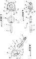
- Figure 1 is a perspective and exploded view of the assembly device of the present invention.
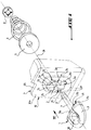
- Figure 2 is a schematic, partial and perspective view of a front bumper mounted on the body of a motor vehicle.
- FIG. 3 is a schematic perspective view of the device of the invention in the unlocked position, associated with an operating hook, according to arrow III in FIG. 2.
- Figure 4 is a view similar to that of Figure 3, but with the assembly device in the locked position.
- FIG. 5 is a schematic view in section of a variant of the device of the invention, along the line VV of FIG. 4.
- Figure 6 is a perspective and exploded view of the locking member of the device of the invention.
- FIG. 7 is an exploded view in longitudinal section of the locking member of FIG. 6.
- FIG. 8 is an exploded view in cross section of the locking member of FIG. 6.
- Figure 9 is a plan view of another variant of the device of Figure 1, along arrow IX, the locking member having been omitted.
- Figures 10 and 11 are broken sections with parallel planes of Figure 9, along the lines X-X and XI-XI, with the locking member in the locked and unlocked position respectively.
- the assembly device of the invention comprises a locking member 1, indexing means 2 and a compression spring 3.
- the spring 3 bears on one of its end turns on the internal surface 4a of a first body element such as a bumper skin 4, by means of a support washer 5 .
- the other end turn of the spring 3 is integral with a retaining washer 6 which adjusts around the free end of a rod 7, in a circular groove 8.
- the rod 7 passes axially through the spring 3, the support washer 5 and is extended at its other end by a substantially annular piece 9 forming the head of the locking member 1.
- the locking member 1 has a general T shape, the leg and the bar of the T respectively forming the rod 7 and the substantially annular part 9.
- the device of the invention is arranged to allow assembly of the bumper element 4 with another body element 10.
- the assembly of elements 4 and 10 is carried out by applying one against the other their facing or external surface 4b and 10b respectively.
- the head 9 of the locking member 1 is capable of coming to bear by its base 11 against the internal surface 10a of the bodywork element 10, so as to come to enclose the elements 4 and 10 between the head 9 of the locking member and spring 3.
- An elongated oblong hole 12 is formed through the second body element 10, the shape of the oblong hole 12 corresponding to the external contour of the base 11 of the head 9.
- the elongated hole 12 must be shaped so as to allow the passage of the head 9 of the locking member 1, when said head 9 is aligned with the elongated hole 12.
- the hole 12 can have any elongated shape, for example rectangular, elliptical or other.
- the elongated hole 12 defined in the direction of its length a longitudinal direction 13 and in the direction of its width a transverse direction 14 (see Figures 1 and 9).
- the rod 7 passes axially through a bore 15 (see FIG. 5) formed in the first bumper element 4 and which is coaxial with the axis 16 of the oblong hole 12.
- the rod 7 is separated from the head 9 by the base 11 forming a shoulder extending in a direction perpendicular to the axis of the rod 7.
- the base 11 has in its length a stepped surface consisting of a main surface 11a extending on either side of the rod 7 by two raised studs 11b adjacent to the rod 7.
- the base 11 of the head 9 also has in its width a stepped surface formed by the main surface 11a or the studs 11b which extend laterally by two underlying shoulders 11c.
- the indexing means 2 form an imprint of a shape complementary to that of the base 11 and formed projecting from the external surface 4b of the bumper element 4.
- the indexing means 2 can be hollowed out in the very thickness of the bodywork element 4.
- the underlying shoulders 11c and the raised studs 11b have substantially bevelled side walls to allow precise and automatic adjustment in the complementary imprint of the indexing means 2.
- the imprint 2 has a hollow or cross-shaped counterbore, centered on the bore 15 and consisting of two pairs 2a and 2c of diametrically opposite surfaces and oriented respectively in the longitudinal direction 13 and transverse 14 for the reception respectively of the main surface 11a and of the studs 11b in the respectively unlocked and locked position of the member 1, and four protrusions 2b formed projecting from the external face 4b of the first element 4, at the four corners of the hollow in the shape of a cross.
- the pair of surfaces 2a is extended, in the longitudinal direction 13, by another pair of surfaces 2d arranged on either side of the bore 15 and at a level below that of the surfaces 2a to receive the studs 11b in the unlocked position of organ 1.
- the head 9 of the locking member 1 is intended to be received between the two pairs of protrusions 2b located on either side of the axis 14 and the axis 13, when the locking member 1 is respectively in the locked or unlocked position.
- the imprint of the indexing means 2 has an axial symmetry with respect to the axis 16.
- the imprint 2 can be formed by molding during the manufacture of the bumper 4, or it can be part of a separate part 17 (shown in broken lines in Figure 1) adaptable through the first element 4, for example by welding or stapling.
- This separate part 17 can also be adapted to the first element 4 by a simple support as better represented in FIGS. 9 to 11.
- the part 17 plays the role here of the first element to be assembled and comprises for example a peripheral flange 17a intended to come resting against the external surface 4a of the first element 4 (acting here as the third element to be assembled) and surrounding the base of the cavity 2 which passes through an elongated bore (not shown) corresponding to this third element.
- the imprint 2 passes through both the third 4 and the second 10 elements to be assembled and the part 17 can be reused or replaced without having to change the body of the vehicle.
- the locking member 1 consists of two parts, the rod 7 being in one piece with a metal ring 18 which fits in an annular housing 19 provided internally in the plastic head 9 separate from rod 7.
- the head 9 can be provided for example in two symmetrical parts 9a, 9b (see FIG. 6) which come to fit around the ring 18 secured to the rod 7.
- the head 9 has a central orifice 20 for the passage, for example, of the end of an operating hook 21, illustrated in FIGS. 3 and 4.
- FIG. 2 shows an overall view of a bumper 4 of a motor vehicle fixed to a front structure 10 by means of the device of the invention indicated by arrow III.
- the head 9 of the locking member 1 is oriented in the longitudinal direction 13 of the oblong hole 12 of the body element 10, so that the 'The bumper 4 can be easily and quickly assembled or separated from the bodywork element 10 by approaching and moving the bumper element 4 away from the element 10 in the axial direction 16.
- This position of the locking member 1 is said to be unlocked and is shown in FIGS. 3 and 11.
- the main surface 11a, the studs 11b and the shoulder 11c of the base 11 rest respectively on the surfaces 2a and 2d of the hollow in the form of a cross and on the top of the protuberances 2b of the imprint 2.
- the head 9 is pulled in the direction of the arrow 22, that is to say in the axial direction 16, and it is rotated by a quarter of a turn as indicated. by the arrow 23 ( Figure 3), using for example the hook 21, so that the head 9 comes to align with the transverse direction 14 above.
- the head 9 is then released against the internal surface 10a of the second element 10, as indicated by the arrow 24 (FIG. 4). It is necessary to pull and release the head 9 in the direction of the axis 16 because in the unlocked position the head 9 is partially engaged in the opening 12.
- the head 9 moves away from the bumper element 4 by a distance equal to the difference in level between the surfaces 2a of the imprint and the internal face 10a of the second element 10 in the assembled position, for example of the order of the thickness of the bodywork element 10, which generates additional compression of the spring 3 in the locked position which adds to the initial preload of the spring 3, in the unlocked position .
- the elements 4 and 10 are assembled by an elastic means 3 preferably having a very high stiffness making it possible to compensate and to collect any shocks in the axial direction 16, to avoid any untimely dislocation of the studs 11b between the protuberances 2b in locked position.
- protuberances 2b project from the internal surface 10a of the second element 10, but these protuberances can alternatively be completely retracted in the oblong hole 12, as visible in FIGS. 10 and 11, the essential point being that these protrusions prevent the rotation of the locking member from its locked position to its unlocked position, unless first exerting axial traction on this member in order to disengage the base 11 from its housing defined between the protrusions 2b and surfaces 2c.
- the device of the invention has the function of ensuring a stable locking of the elements 4 and 10 together, even in the presence of vibrations or significant shocks, while allowing a simple and rapid unlocking for the replacement of the one of these.
- the shape of the base 11 can be modified without departing from the scope of the present invention and for example have a perfectly flat surface, in the case for example where the protuberances 2b protrude from the second element 10.
Abstract
Description
La présente invention concerne un dispositif d'assemblage d'au moins deux éléments par exemple de carrosserie automobile. Un tel dispositif s'applique notamment à la fixation d'un pare-chocs sur la carrosserie ou le châssis d'un véhicule automobile.The present invention relates to a device for assembling at least two elements, for example of automobile bodywork. Such a device applies in particular to the fixing of a bumper on the bodywork or the chassis of a motor vehicle.
La carrosserie d'un véhicule automobile est généralement constituée de différents éléments de formes et de matériaux variables, qui sont généralement assemblés ensemble par des dispositifs de fixation du type vis-rondelle-écrou.The bodywork of a motor vehicle is generally made up of different elements of variable shapes and materials, which are generally assembled together by fixing devices of the screw-washer-nut type.
Ces dispositifs de fixation connus ne permettent cependant pas un assemblage et un démontage rapides des éléments de carrosserie pour remplacer les éléments détériorés, en cas par exemple d'un choc ou d'une usure trop importante.These known fastening devices do not, however, allow rapid assembly and disassembly of the bodywork elements to replace the deteriorated elements, in the event, for example, of an impact or excessive wear.
La rigidité de ces dispositifs de fixation connus constitue également un inconvénient, notamment lorsque des éléments de carrosserie adjacents subissent des déformations différentes, à la suite par exemple de chocs ou d'écarts de température importants.The rigidity of these known fastening devices also constitutes a drawback, in particular when adjacent body elements undergo different deformations, for example as a result of shocks or significant temperature differences.
En effet, de telles liaisons rigides constituent des zones de concentration de contrainte qui peuvent conduire à la rupture de la liaison ou à la déformation de l'élément de carrosserie adjacent à celui qui subit la contrainte.Indeed, such rigid connections constitute stress concentration zones which can lead to the rupture of the connection or to the deformation of the bodywork element adjacent to that which is subjected to the stress.
En outre, ces dispositifs de fixation connus ne permettent pas de positionner avec précision et d'adapter les différents éléments carrosserie entre eux, en fonction de leurs tolérances de fabrication, ce qui peut nuire à l'aspect général extérieur du véhicule.In addition, these known fastening devices do not allow positioning with precision and adapting the various bodywork elements to one another, according to their manufacturing tolerances, which can harm the general exterior appearance of the vehicle.
La présente invention a donc pour but d'éliminer les inconvénients ci-dessus et de proposer un dispositif d'assemblage d'au moins deux éléments par exemple de carrosserie automobile, permettant un positionnement précis de ces derniers les uns par rapport aux autres, qui soit facilement montable et démontable et qui assure un verrouillage stable même en présence de fortes sollicitations externes.The present invention therefore aims to eliminate the above drawbacks and to propose a device for assembling at least two elements, for example of automobile bodywork, allowing precise positioning of the latter relative to each other, which is easily mounted and dismountable and which ensures stable locking even in the presence of strong external stresses.
A cet effet, la présente invention a pour objet un dispositif d'assemblage d'au moins deux éléments adjacents, par exemple de carrosserie automobile, dont les surfaces externes sont destinées à venir en appui l'une contre l'autre, du type comportant un organe de verrouillage constitué d'une tige se prolongeant par une tête s'étendant sensiblement dans une direction perpendiculaire à la tige, un moyen élastique de compression prenant appui à une extrémité sur la surface interne d'un premier élément à assembler et dont l'autre extrémité est solidaire de l'extrémité libre de ladite tige qui traverse axialement un perçage ménagé à travers la paroi du premier élément et un trou allongé ménagé à travers le second élément à assembler, le trou allongé ayant une forme correspondante à la tête de l'organe de verrouillage pour permettre le passage de ladite tête à travers le second élément en position déverrouillée dans laquelle la tête est alignée avec le trou allongé, et des moyens d'indexage formés sur au moins l'un des éléments à assembler et destinés à coopérer avec la tête de l'organe en position verrouillée dans laquelle la tête prend appui transversalement par rapport audit trou allongé par l'intermédiaire de la surface principale de sa base sur la surface interne du second élément, opposée à la surface interne du premier élément, caractérisé en ce que les moyens d'indexage sont formés d'au moins deux protubérances en saillie de la face externe du premier élément, de part et d'autre du perçage axial et aptes à venir se loger dans le trou allongé, les deux protubérances étant disposées sensiblement symétriquement par rapport à la direction transversale du trou allongé précité de façon que la base vienne s'emboîter entre elles en position verrouillée de l'organe, empêchant tout déverrouillage par simple rotation de la tête de l'organe.To this end, the subject of the present invention is a device for assembling at least two adjacent elements, for example of automobile bodywork, the external surfaces of which are intended to bear against one another, of the type comprising a locking member consisting of a rod extending by a head extending substantially in a direction perpendicular to the rod, an elastic compression means bearing at one end on the internal surface of a first element to be assembled and whose l the other end is integral with the free end of said rod which passes axially through a bore formed through the wall of the first element and an elongated hole formed through the second element to be assembled, the elongated hole having a shape corresponding to the head of the locking member to allow the passage of said head through the second element in the unlocked position in which the head is aligned with the elongated hole, and indexing means formed on at least one of the elements to be assembled and intended to cooperate with the head of the member in the locked position in which the head bears transversely with respect to said hole elongated by the intermediate the main surface of its base on the internal surface of the second element, opposite the internal surface of the first element, characterized in that the indexing means are formed by at least two protrusions projecting from the external face of the first element, on either side of the axial bore and able to be housed in the elongated hole, the two protrusions being arranged substantially symmetrically with respect to the transverse direction of the above-mentioned elongated hole so that the base comes to fit together in the locked position of the member, preventing any unlocking by simple rotation of the head of the member.
L'organe de verrouillage peut présenter avantageusement une forme générale en T, la jambe et la barre du T formant respectivement la tige et la tête de l'organe.The locking member may advantageously have a general T shape, the leg and the bar of the T respectively forming the rod and the head of the member.
Selon une autre caractéristique de l'invention, les moyens d'indexage comportent dans la direction longitudinale du trou allongé des surfaces pour la réception de la surface principale de la base en position déverrouillée, lesdites surfaces étant logées à l'intérieur du trou allongé de sorte que la tête est partiellement engagée dans celui-ci et située à un niveau axialement différent de sa position verrouillée où la compression engendrée par le moyen élastique est plus élevée.According to another characteristic of the invention, the indexing means comprise in the longitudinal direction of the elongated hole surfaces for the reception of the main surface of the base in the unlocked position, said surfaces being housed inside the elongated hole of so that the head is partially engaged therein and located at an axially different level from its locked position where the compression generated by the elastic means is higher.
Dans une variante de réalisation, les moyens d'indexage font partie d'une pièce distincte adaptable à travers le premier élément, par exemple par soudage ou agrafage.In an alternative embodiment, the indexing means form part of a separate part adaptable through the first element, for example by welding or stapling.
Avantageusement, le premier élément précité constitue la pièce distincte sur laquelle sont formés les moyens d'indexage, ladite pièce venant prendre en sandwich à la fois un troisième élément à assembler et le second élément précité par l'intermédiaire d'une surface périphérique entourant la base des moyens d'indexage et venant en appui contre la face interne du troisième élément qui est percé d'une ouverture allongée correspondante au trou allongé précité pour le passage des moyens d'indexage.Advantageously, the first aforementioned element constitutes the separate part on which the indexing means are formed, said part coming to sandwich both a third element to be assembled and the aforementioned second element by means of a peripheral surface surrounding the base of the indexing means and coming to bear against the internal face of the third element which is pierced with an elongated opening corresponding to the above-mentioned elongated hole for the passage of the indexing means.
Selon encore une autre caractéristique de l'invention, les moyens d'indexage forment une empreinte de forme complémentaire à celle de la base de l'organe de verrouillage, ce qui assure un positionnement précis des différents éléments à assembler.According to yet another characteristic of the invention, the indexing means form an imprint of shape complementary to that of the base of the locking member, which ensures precise positioning of the various elements to be assembled.
Dans une variante de réalisation, les protubérances précitées font saillie de la surface interne du second élément pour bloquer en rotation la base en position verrouillée.In an alternative embodiment, the aforementioned protrusions protrude from the internal surface of the second element to block the base in rotation in the locked position.
Dans ce cas, la base de la tête de l'organe de verrouillage peut présenter une surface parfaitement plane.In this case, the base of the head of the locking member may have a perfectly flat surface.
Dans une autre variante, la base précitée de l'organe de verrouillage comporte une partie axialement surélevée par rapport à sa surface principale et destinée à s'emboîter en position verrouillée entre les protubérances qui sont logées de préférence entièrement dans le trou allongé du second élément.In another variant, the aforementioned base of the locking member comprises an axially raised portion relative to its main surface and intended to fit in the locked position between the protrusions which are preferably housed entirely in the elongated hole of the second element .
Avantageusement, la tige et la tête de l'organe de verrouillage sont en matériaux différents.Advantageously, the rod and the head of the locking member are made of different materials.
La tige peut être par exemple métallique pour qu'elle résiste aux contraintes exercées par le ressort de compression et par les éléments de carrosserie et la tête en matière plastique pour éviter d'endommager l'aspect externe de la carrosserie, par exemple de rayer la peinture.The rod may for example be metallic so that it resists the stresses exerted by the compression spring and by the bodywork elements and the plastic head to avoid damaging the external appearance of the bodywork, for example to scratch the painting.
Selon une autre caractéristique de l'invention, la tête de l'organe de verrouillage est percée d'un orifice destiné à coopérer avec un outil tel qu'un crochet servant à positionner sélectivement l'organe en position verrouillée ou déverrouillée, par traction axiale.According to another characteristic of the invention, the head of the locking member is pierced with an orifice intended to cooperate with a tool such as a hook used to selectively position the member in the locked or unlocked position, by axial traction .
L'invention sera mieux comprise et d'autres buts, caractéristiques, détails et avantages de celle-ci apparaîtront plus clairement dans la description explicative qui va suivre de plusieurs variantes de réalisation particulières, actuellement préférées de l'invention, données uniquement à titre d'exemple illustratif et non limitatif, en référence aux dessins schématiques annexés, dans lesquels :The invention will be better understood and other aims, characteristics, details and advantages thereof will appear more clearly in the explanatory description which follows of several particular, currently preferred alternative embodiments of the invention, given solely by way of illustration. illustrative and nonlimiting example, with reference to the appended schematic drawings, in which:
La figure 1 est une vue en perspective et éclatée du dispositif d'assemblage de la présente invention.Figure 1 is a perspective and exploded view of the assembly device of the present invention.
La figure 2 est une vue schématique, partielle et en perspective d'un pare-chocs avant monté sur la carrosserie d'un véhicule automobile.Figure 2 is a schematic, partial and perspective view of a front bumper mounted on the body of a motor vehicle.
La figure 3 est une vue schématique et en perspective du dispositif de l'invention en position déverrouillée, associé à un crochet de manoeuvre, suivant la flèche III sur la figure 2.FIG. 3 is a schematic perspective view of the device of the invention in the unlocked position, associated with an operating hook, according to arrow III in FIG. 2.
La figure 4 est une vue similaire à celle de la figure 3, mais avec le dispositif d'assemblage en position verrouillée.Figure 4 is a view similar to that of Figure 3, but with the assembly device in the locked position.
La figure 5 est une vue schématique et en coupe d'une variante du dispositif de l'invention, suivant la ligne V-V de la figure 4.FIG. 5 is a schematic view in section of a variant of the device of the invention, along the line VV of FIG. 4.
La figure 6 est une vue en perspective et éclatée de l'organe de verrouillage du dispositif de l'invention.Figure 6 is a perspective and exploded view of the locking member of the device of the invention.
La figure 7 est une vue éclatée et en coupe longitudinale de l'organe de verrouillage de la figure 6.FIG. 7 is an exploded view in longitudinal section of the locking member of FIG. 6.
La figure 8 est une vue éclatée et en coupe transversale de l'organe de verrouillage de la figure 6.FIG. 8 is an exploded view in cross section of the locking member of FIG. 6.
La figure 9 est une vue plane d'une autre variante du dispositif de la figure 1, suivant la flèche IX, l'organe de verrouillage ayant été omis.Figure 9 is a plan view of another variant of the device of Figure 1, along arrow IX, the locking member having been omitted.
Les figures 10 et 11 sont des coupes brisées à plans parallèles de la figure 9, suivant les lignes X-X et XI-XI, avec l'organe de verrouillage en position verrouillée et déverrouillée respectivement.Figures 10 and 11 are broken sections with parallel planes of Figure 9, along the lines X-X and XI-XI, with the locking member in the locked and unlocked position respectively.
Suivant l'exemple de réalisation représenté sur la figure 1, le dispositif d'assemblage de l'invention comporte un organe de verrouillage 1, des moyens d'indexage 2 et un ressort de compression 3.According to the embodiment shown in FIG. 1, the assembly device of the invention comprises a locking member 1, indexing means 2 and a
On a représenté sur la figure 1 un ressort de compression conique, mais bien entendu, on peut prévoir en variante un ressort hélicoïdal, à lame ou tout autre moyen élastique.There is shown in Figure 1 a conical compression spring, but of course, one can alternatively provide a coil spring, leaf or any other elastic means.
Le ressort 3 prend appui à l'une de ses spires d'extrémités sur la surface interne 4a d'un premier élément de carrosserie tel qu'une peau de pare-chocs 4, par l'intermédiaire d'une rondelle d'appui 5.The
L'autre spire d'extrémité du ressort 3 est solidaire d'une rondelle de retenue 6 qui vient s'ajuster autour de l'extrémité libre d'une tige 7, dans une gorge circulaire 8.The other end turn of the
La tige 7 traverse axialement le ressort 3, la rondelle d'appui 5 et se prolonge à son autre extrémité par une pièce sensiblement annulaire 9 formant la tête de l'organe de verrouillage 1.The
L'organe de verrouillage 1 présente une forme générale en T, la jambe et la barre du T formant respectivement la tige 7 et la pièce sensiblement annulaire 9.The locking member 1 has a general T shape, the leg and the bar of the T respectively forming the
Le dispositif de l'invention est agencé pour permettre l'assemblage de l'élément de pare-chocs 4 avec un autre élément de carrosserie 10. L'assemblage des éléments 4 et 10 s'effectue en appliquant l'une contre l'autre leur surface en regard ou externe 4b et 10b respectivement.The device of the invention is arranged to allow assembly of the
La tête 9 de l'organe de verrouillage 1 est apte à venir en appui par sa base 11 contre la surface interne 10a de l'élément de carrosserie 10, de manière à venir enserrer les éléments 4 et 10 entre la tête 9 de l'organe de verrouillage et le ressort 3.The
Un trou allongé de forme oblongue 12 est ménagé à travers le second élément de carrosserie 10, la forme du trou oblong 12 correspondant au contour externe de la base 11 de la tête 9.An elongated
De manière générale, le trou allongé 12 doit être conformé de manière à permettre le passage de la tête 9 de l'organe de verrouillage 1, lorsque ladite tête 9 est alignée avec le trou allongé 12.In general, the
Bien entendu, le trou 12 peut présenter une forme allongée quelconque, par exemple rectangulaire, en ellipse ou autre.Of course, the
Le trou allongé 12 défini dans le sens de sa longueur une direction longitudinale 13 et dans le sens de sa largeur une direction transversale 14 (voir figures 1 et 9).The
La tige 7 traverse axialement un perçage 15 (voir figure 5) ménagé dans le premier élément de pare-chocs 4 et qui est coaxial avec l'axe 16 du trou oblong 12.The
La tige 7 est séparée de la tête 9 par la base 11 formant un épaulement s'étendant suivant une direction perpendiculaire à l'axe de la tige 7.The
La base 11 présente dans sa longueur une surface étagée constituée d'une surface principale 11a se prolongeant de part et d'autre de la tige 7 par deux plots surélevés 11b adjacents à la tige 7.The
La base 11 de la tête 9 présente également dans sa largeur une surface étagée constituée par la surface principale 11a ou les plots 11b qui se prolongent latéralement par deux épaulements sous-jacents 11c.The
Les moyens d'indexage 2 forment une empreinte de forme complémentaire à celle de la base 11 et ménagée en saillie de la surface externe 4b de l'élément de pare-chocs 4.The indexing means 2 form an imprint of a shape complementary to that of the
On voit sur la variante de la figure 5 que les moyens d'indexage 2 peuvent être formés en creux dans l'épaisseur même de l'élément de carrosserie 4.It can be seen in the variant of FIG. 5 that the indexing means 2 can be hollowed out in the very thickness of the
Les épaulements sous-jacents 11c et les plots surélevés 11b présentent des parois latérales sensiblement biseautées pour permettre un ajustement précis et automatique dans l'empreinte complémentaire des moyens d'indexage 2.The
Comme cela est mieux visible sur la figure 9, l'empreinte 2 comporte un creux ou un lamage en forme de croix, centré sur le perçage 15 et constitué de deux paires 2a et 2c de surfaces diamétralement opposées et orientées respectivement dans la direction longitudinale 13 et transversale 14 pour la réception respectivement de la surface principale 11a et des plots 11b en position respectivement déverrouillée et verrouillée de l'organe 1, et quatre protubérances 2b ménagées en saillie de la face externe 4b du premier élément 4, aux quatre coins du creux en forme de croix.As is better visible in FIG. 9, the
La paire de surfaces 2a se prolonge, dans la direction longitudinale 13, par une autre paire de surfaces 2d disposées de part et d'autre du perçage 15 et à un niveau inférieur à celui des surfaces 2a pour recevoir les plots 11b en position déverrouillée de l'organe 1.The pair of
On voit clairement sur les figures 1 et 9 que le creux en forme de croix est plus long dans la direction longitudinale 13 que dans sa direction transversale 14.It is clearly seen in FIGS. 1 and 9 that the cross-shaped recess is longer in the
La tête 9 de l'organe de verrouillage 1 est destinée à être reçue entre les deux paires de protubérances 2b situées de part et d'autre de l'axe 14 et de l'axe 13, lorsque l'organe de verrouillage 1 est respectivement en position verrouillée ou déverrouillée.The
L'empreinte des moyens d'indexage 2 présente une symétrie axiale par rapport à l'axe 16.The imprint of the indexing means 2 has an axial symmetry with respect to the
L'empreinte 2 peut être formée par moulage lors de la fabrication du pare-chocs 4, ou elle peut faire partie d'une pièce distincte 17 (représentée en traits interrompus sur la figure 1) adaptable à travers le premier élément 4, par exemple par soudage ou agrafage.The
Cette pièce distincte 17 peut également être adaptée sur le premier élément 4 par un appui simple comme mieux représenté sur les figures 9 à 11. La pièce 17 joue le rôle ici de premier élément à assembler et comporte par exemple une collerette périphérique 17a destinée à venir en appui contre la surface externe 4a du premier élément 4 (faisant office ici de troisième élément à assembler) et entourant la base de l'empreinte 2 qui traverse un perçage allongé (non représenté) correspondant de ce troisième élément.This
Dans ce cas, l'empreinte 2 traverse à la fois le troisième 4 et le second 10 éléments à assembler et la pièce 17 peut être réutilisée ou remplacée sans avoir à changer la carrosserie du véhicule.In this case, the
On voit sur les figures 6 à 8, que l'organe de verrouillage 1 est constitué de deux parties, la tige 7 étant monobloc avec un anneau métallique 18 qui vient s'ajuster dans un logement annulaire 19 prévu intérieurement dans la tête en plastique 9 séparée de la tige 7.We see in Figures 6 to 8, that the locking member 1 consists of two parts, the
La tête 9 peut être prévue par exemple en deux parties symétriques 9a, 9b (voir figure 6) qui viennent s'emboîter autour de l'anneau 18 solidaire de la tige 7.The
La tête 9 présente un orifice central 20 pour le passage par exemple de l'extrémité d'un crochet de manoeuvre 21, illustré sur les figures 3 et 4.The
On va maintenant décrire le fonctionnement du dispositif d'assemblage de l'invention en référence aux figures 2 à 5 et 10 et 11.We will now describe the operation of the assembly device of the invention with reference to FIGS. 2 to 5 and 10 and 11.
On a représenté sur la figure 2, une vue d'ensemble d'un pare-chocs 4 d'un véhicule automobile fixé sur une structure avant 10 par l'intermédiaire du dispositif de l'invention indiqué par la flèche III.FIG. 2 shows an overall view of a
Une fois le dispositif de l'invention monté sur l'élément de carrosserie 4, la tête 9 de l'organe de verrouillage 1 est orientée dans la direction longitudinale 13 du trou oblong 12 de l'élément de carrosserie 10, de sorte que l'on peut facilement et rapidement assembler ou séparer le pare-chocs 4 de l'élément de carrosserie 10 en approchant et en éloignant l'élément de pare-chocs 4 de l'élément 10 dans la direction axiale 16.Once the device of the invention mounted on the
Cette position de l'organe de verrouillage 1 est dite déverrouillée et elle est représentée sur les figures 3 et 11.This position of the locking member 1 is said to be unlocked and is shown in FIGS. 3 and 11.
Dans cette position déverrouillée, la surface principale 11a, les plots 11b et l'épaulement 11c de la base 11 reposent respectivement sur les surfaces 2a et 2d du creux en forme de croix et sur le sommet des protubérances 2b de l'empreinte 2.In this unlocked position, the
Bien entendu, un triple contact simultané entre la base 11 et l'empreinte 2 étant pratiquement difficile à réaliser, il est probable que seule l'une des surfaces de la base 11 soit en contact avec l'empreinte, les autres surfaces étant simplement au droit des surfaces correspondantes de l'empreinte.Of course, a simultaneous triple contact between the base 11 and the
Pour déplacer l'organe de verrouillage 1 en position verrouillée, on tire sur la tête 9 dans la direction de la flèche 22 c'est-à-dire dans la direction axiale 16 et on la fait pivoter d'un quart de tour comme indiqué par la flèche 23 (figure 3), à l'aide par exemple du crochet 21, de sorte que la tête 9 vienne s'aligner avec la direction transversale 14 précitée.To move the locking member 1 in the locked position, the
On relâche ensuite la tête 9 contre la surface interne 10a du second élément 10, comme indiqué par la flèche 24 (figure 4). Il est nécessaire de tirer et de relâcher la tête 9 dans la direction de l'axe 16 car en position déverrouillée la tête 9 est partiellement engagée dans l'ouverture 12.The
Dans cette position verrouillée, la surface principale 11a de la base 11 repose contre la surface interne 10a de l'élément de carrosserie 10 et on obtient ainsi l'assemblage des éléments de carrosserie 4 et 10.In this locked position, the
Lors du passage de la position déverrouillée à la position verrouillée, la tête 9 s'écarte de l'élément de pare-chocs 4 d'une distance égale au dénivellé entre les surfaces 2a de l'empreinte et la face interne 10a du second élément 10 en position assemblée, par exemple de l'ordre de l'épaisseur de l'élément de carrosserie 10, ce qui engendre une compression additionnelle du ressort 3 en position verrouillée qui s'ajoute à la précontrainte initiale du ressort 3, en position déverrouillée.When passing from the unlocked position to the locked position, the
En effet, comme cela apparaît clairement sur les figures 10 et 11, la tête 9 de l'organe de verrouillage est surélevée en position verrouillée par rapport à sa position déverrouillée.Indeed, as is clearly seen in Figures 10 and 11, the
Les éléments 4 et 10 sont assemblés par un moyen élastique 3 ayant de préférence une raideur très élevée permettant de compenser et d'encaisser les chocs éventuels dans la direction axiale 16, pour éviter tout déboîtement intempestif des plots 11b d'entre les protubérances 2b en position verrouillée.The
On voit sur les figures 10 et 11 que les surfaces 2a et 2c sont sensiblement au même niveau, mais on pourrait prévoir ces surfaces à des niveaux différents, comme cela est visible sur la figure 1, sans sortir du cadre de l'invention.We see in Figures 10 and 11 that the
On voit également sur la figure 1 que les protubérances 2b font saillie de la surface interne 10a du second élément 10, mais ces protubérances peuvent en variante être complètement escamotées dans le trou oblong 12, comme visible sur les figures 10 et 11, le point essentiel étant que ces protubérances empêchent la rotation de l'organe de verrouillage de sa position verrouillée vers sa position déverrouillée, à moins d'exercer d'abord une traction axiale sur cet organe afin de dégager la base 11 de son logement défini entre les protubérances 2b et les surfaces 2c.It can also be seen in FIG. 1 that the
En effet, le dispositif de l'invention a pour fonction d'assurer un verrouillage stable des éléments 4 et 10 ensemble, même en présence de vibrations ou de chocs importants, tout en permettant un déverrouillage simple et rapide en vue du remplacement de l'un de ces éléments.Indeed, the device of the invention has the function of ensuring a stable locking of the
Bien entendu la forme de la base 11 peut être modifiée sans sortir du cadre de la présente invention et présenter par exemple une surface parfaitement plane, dans le cas par exemple où les protubérances 2b font saillie hors du second élément 10.Of course, the shape of the base 11 can be modified without departing from the scope of the present invention and for example have a perfectly flat surface, in the case for example where the
Bien que l'invention ait été décrite en liaison avec plusieurs variantes de réalisation particulières, il est évident qu'elle n'y est nullement limitée et qu'elle comprend tous les équivalents techniques des moyens décrits et leurs combinaisons si celles-ci entrent dans le cadre des revendications qui suivent.Although the invention has been described in conjunction with several particular variant embodiments, it is obvious that it is in no way limited thereto and that it includes all the technical equivalents of the means described and their combinations if these fall within the scope of the claims which follow.
Claims (10)
Applications Claiming Priority (2)
| Application Number | Priority Date | Filing Date | Title |
|---|---|---|---|
| FR9406131A FR2720126B1 (en) | 1994-05-19 | 1994-05-19 | Device for assembling at least two elements, for example of automobile bodywork. |
| FR9406131 | 1994-05-19 |
Publications (3)
| Publication Number | Publication Date |
|---|---|
| EP0687819A2 true EP0687819A2 (en) | 1995-12-20 |
| EP0687819A3 EP0687819A3 (en) | 1996-12-18 |
| EP0687819B1 EP0687819B1 (en) | 2002-09-18 |
Family
ID=9463355
Family Applications (1)
| Application Number | Title | Priority Date | Filing Date |
|---|---|---|---|
| EP19950401149 Expired - Lifetime EP0687819B1 (en) | 1994-05-19 | 1995-05-17 | Fastening device for at least two elements, e.g. for automobile bodywork |
Country Status (4)
| Country | Link |
|---|---|
| EP (1) | EP0687819B1 (en) |
| DE (1) | DE69528215T2 (en) |
| ES (1) | ES2182877T3 (en) |
| FR (1) | FR2720126B1 (en) |
Cited By (4)
| Publication number | Priority date | Publication date | Assignee | Title |
|---|---|---|---|---|
| FR2764350A1 (en) * | 1997-06-05 | 1998-12-11 | Peugeot | Fastener for assembly of bumper units to chassis or bodywork of motor vehicles |
| FR2781019A1 (en) * | 1998-07-09 | 2000-01-14 | Daimler Chrysler Ag | Clamp arrangement for joining sheet-like components of motor vehicle bodies |
| FR2882796A1 (en) * | 2005-03-03 | 2006-09-08 | Lisi Automotive Rapid Soc Par | Superimposed panels e.g. metal plates, assembling device, has control lever with cam mounted rotatably with respect to support head part, between its assembling and retaining positions, against lugs in its retaining position |
| DE102005011351B4 (en) * | 2005-03-11 | 2007-10-31 | Siemens Ag | Lever and housing arrangement |
Family Cites Families (8)
| Publication number | Priority date | Publication date | Assignee | Title |
|---|---|---|---|---|
| GB419926A (en) * | 1933-05-29 | 1934-11-21 | Jacques Francois Gabriel Chobe | Improvements in fastenings |
| US2485010A (en) * | 1945-04-05 | 1949-10-18 | Camloc Fastener Corp | Fastener structure |
| BE620962A (en) * | 1962-07-31 | |||
| GB1154684A (en) * | 1967-02-10 | 1969-06-11 | Ft Products Ltd | An Improved Fastener. |
| DE6602831U (en) * | 1967-02-13 | 1969-06-26 | Siemens Ag | DEVICE FOR FASTENING A COVER PLATE |
| US4047266A (en) * | 1976-03-15 | 1977-09-13 | Southco, Inc. | Quick action fastener |
| DE3612199C2 (en) * | 1986-04-11 | 1994-08-04 | Camloc Gmbh | Device for releasably attaching a plate-shaped component to a base with a T-slot open towards the component |
| FR2636686B1 (en) * | 1988-09-22 | 1991-01-11 | Peugeot | FIXING PLOT FOR MISCELLANEOUS MOUNTS AND ANY SUPPORT PROVIDED WITH THIS PLOT |
-
1994
- 1994-05-19 FR FR9406131A patent/FR2720126B1/en not_active Expired - Fee Related
-
1995
- 1995-05-17 DE DE1995628215 patent/DE69528215T2/en not_active Expired - Fee Related
- 1995-05-17 ES ES95401149T patent/ES2182877T3/en not_active Expired - Lifetime
- 1995-05-17 EP EP19950401149 patent/EP0687819B1/en not_active Expired - Lifetime
Non-Patent Citations (1)
| Title |
|---|
| None |
Cited By (5)
| Publication number | Priority date | Publication date | Assignee | Title |
|---|---|---|---|---|
| FR2764350A1 (en) * | 1997-06-05 | 1998-12-11 | Peugeot | Fastener for assembly of bumper units to chassis or bodywork of motor vehicles |
| FR2781019A1 (en) * | 1998-07-09 | 2000-01-14 | Daimler Chrysler Ag | Clamp arrangement for joining sheet-like components of motor vehicle bodies |
| US6209940B1 (en) | 1998-07-09 | 2001-04-03 | Daimlerchrysler Ag | System for the assembly of laminar components, especially parts of the external skin of a motor vehicle |
| FR2882796A1 (en) * | 2005-03-03 | 2006-09-08 | Lisi Automotive Rapid Soc Par | Superimposed panels e.g. metal plates, assembling device, has control lever with cam mounted rotatably with respect to support head part, between its assembling and retaining positions, against lugs in its retaining position |
| DE102005011351B4 (en) * | 2005-03-11 | 2007-10-31 | Siemens Ag | Lever and housing arrangement |
Also Published As
| Publication number | Publication date |
|---|---|
| EP0687819B1 (en) | 2002-09-18 |
| FR2720126B1 (en) | 1996-08-09 |
| DE69528215T2 (en) | 2003-05-08 |
| DE69528215D1 (en) | 2002-10-24 |
| EP0687819A3 (en) | 1996-12-18 |
| ES2182877T3 (en) | 2003-03-16 |
| FR2720126A1 (en) | 1995-11-24 |
Similar Documents
| Publication | Publication Date | Title |
|---|---|---|
| EP1721815B1 (en) | Fixation device of a saddle on the head of the saddle pin. | |
| EP1345804B1 (en) | Device for clamping an adjustable element relative to a support assembly | |
| FR2845741A1 (en) | RIVET WITH ELASTIC LEGS | |
| EP2107432A1 (en) | Pushbutton control device for a watch | |
| FR2809684A1 (en) | FOLDABLE ARMREST | |
| FR2974602A1 (en) | ASSEMBLY ASSEMBLY OF TWO PARTS OF A MOTOR VEHICLE | |
| EP0687819B1 (en) | Fastening device for at least two elements, e.g. for automobile bodywork | |
| WO2015193596A1 (en) | Assembly of a structural element of a motor vehicle and a functional element | |
| WO2018015691A1 (en) | Headrest for a motor vehicle seat | |
| EP0879929A1 (en) | Key head forming a casing containing an electronic device | |
| FR2805301A1 (en) | RETAINER FOR A MOTOR VEHICLE LOCK, METHOD FOR MANUFACTURING IT, AND LOCK COMPRISING SUCH A RETAINER | |
| EP1669269A1 (en) | Self locking joint between a ball head actuating rod and a flat part | |
| EP0936128B1 (en) | Steering system, steering wheel and column for such a system | |
| CH703079B1 (en) | Device for fixing interchangeable bracelet to case of watch, has locking unit locking stem such that rotation of wheel along its transverse axis drives transverse displacement of stems for fastening or detaching of bracelet from watch case | |
| EP2123919B1 (en) | Rigid assembly of tubular parts | |
| EP2168804A1 (en) | System for precisely mounting a fuel door in an opening made in the metal sheet of an automobile body | |
| EP1179469B1 (en) | Steering column for a motor vehicle steering system | |
| EP3938667B1 (en) | Pyrotechnic nut releasing device | |
| EP0208582A1 (en) | Winding shaft, in particular for a safety belt | |
| FR2722620A3 (en) | Electrical contact release tool for multiple terminal connectors | |
| FR2702728A1 (en) | Improved anti-theft device for a motor cycle equipped with a drilled brake disc | |
| WO2011098700A1 (en) | Motor vehicle hitch device and vehicle equipped with such a hitch device | |
| EP0936127B1 (en) | Steering wheel for a vehicle | |
| EP1751404B1 (en) | Valve actuating device | |
| EP0761988A1 (en) | Device for fastening an element, especially a solenoid valve of a washing machine, onto a holding plate |
Legal Events
| Date | Code | Title | Description |
|---|---|---|---|
| PUAI | Public reference made under article 153(3) epc to a published international application that has entered the european phase |
Free format text: ORIGINAL CODE: 0009012 |
|
| AK | Designated contracting states |
Kind code of ref document: A2 Designated state(s): DE ES FR GB IT |
|
| PUAL | Search report despatched |
Free format text: ORIGINAL CODE: 0009013 |
|
| AK | Designated contracting states |
Kind code of ref document: A3 Designated state(s): DE ES FR GB IT |
|
| 17P | Request for examination filed |
Effective date: 19970329 |
|
| 17Q | First examination report despatched |
Effective date: 19980803 |
|
| GRAG | Despatch of communication of intention to grant |
Free format text: ORIGINAL CODE: EPIDOS AGRA |
|
| GRAG | Despatch of communication of intention to grant |
Free format text: ORIGINAL CODE: EPIDOS AGRA |
|
| GRAH | Despatch of communication of intention to grant a patent |
Free format text: ORIGINAL CODE: EPIDOS IGRA |
|
| GRAH | Despatch of communication of intention to grant a patent |
Free format text: ORIGINAL CODE: EPIDOS IGRA |
|
| GRAA | (expected) grant |
Free format text: ORIGINAL CODE: 0009210 |
|
| AK | Designated contracting states |
Kind code of ref document: B1 Designated state(s): DE ES FR GB IT |
|
| REG | Reference to a national code |
Ref country code: GB Ref legal event code: FG4D Free format text: NOT ENGLISH |
|
| REF | Corresponds to: |
Ref document number: 69528215 Country of ref document: DE Date of ref document: 20021024 |
|
| GBT | Gb: translation of ep patent filed (gb section 77(6)(a)/1977) |
Effective date: 20021203 |
|
| REG | Reference to a national code |
Ref country code: ES Ref legal event code: FG2A Ref document number: 2182877 Country of ref document: ES Kind code of ref document: T3 |
|
| PLBE | No opposition filed within time limit |
Free format text: ORIGINAL CODE: 0009261 |
|
| STAA | Information on the status of an ep patent application or granted ep patent |
Free format text: STATUS: NO OPPOSITION FILED WITHIN TIME LIMIT |
|
| 26N | No opposition filed |
Effective date: 20030619 |
|
| REG | Reference to a national code |
Ref country code: GB Ref legal event code: 746 Effective date: 20070117 |
|
| PGFP | Annual fee paid to national office [announced via postgrant information from national office to epo] |
Ref country code: ES Payment date: 20080508 Year of fee payment: 14 |
|
| PGFP | Annual fee paid to national office [announced via postgrant information from national office to epo] |
Ref country code: IT Payment date: 20080520 Year of fee payment: 14 |
|
| PGFP | Annual fee paid to national office [announced via postgrant information from national office to epo] |
Ref country code: GB Payment date: 20080424 Year of fee payment: 14 |
|
| PGFP | Annual fee paid to national office [announced via postgrant information from national office to epo] |
Ref country code: FR Payment date: 20090527 Year of fee payment: 15 Ref country code: DE Payment date: 20090603 Year of fee payment: 15 |
|
| GBPC | Gb: european patent ceased through non-payment of renewal fee |
Effective date: 20090517 |
|
| PG25 | Lapsed in a contracting state [announced via postgrant information from national office to epo] |
Ref country code: GB Free format text: LAPSE BECAUSE OF NON-PAYMENT OF DUE FEES Effective date: 20090517 |
|
| REG | Reference to a national code |
Ref country code: ES Ref legal event code: FD2A Effective date: 20090518 |
|
| PG25 | Lapsed in a contracting state [announced via postgrant information from national office to epo] |
Ref country code: ES Free format text: LAPSE BECAUSE OF NON-PAYMENT OF DUE FEES Effective date: 20090518 |
|
| REG | Reference to a national code |
Ref country code: FR Ref legal event code: ST Effective date: 20110131 |
|
| PG25 | Lapsed in a contracting state [announced via postgrant information from national office to epo] |
Ref country code: IT Free format text: LAPSE BECAUSE OF NON-PAYMENT OF DUE FEES Effective date: 20090517 |
|
| PG25 | Lapsed in a contracting state [announced via postgrant information from national office to epo] |
Ref country code: DE Free format text: LAPSE BECAUSE OF NON-PAYMENT OF DUE FEES Effective date: 20101201 |
|
| PG25 | Lapsed in a contracting state [announced via postgrant information from national office to epo] |
Ref country code: FR Free format text: LAPSE BECAUSE OF NON-PAYMENT OF DUE FEES Effective date: 20100531 |