EP4321384A1 - Lastenträger für ein kraftfahrzeug - Google Patents
Lastenträger für ein kraftfahrzeug Download PDFInfo
- Publication number
- EP4321384A1 EP4321384A1 EP23183989.5A EP23183989A EP4321384A1 EP 4321384 A1 EP4321384 A1 EP 4321384A1 EP 23183989 A EP23183989 A EP 23183989A EP 4321384 A1 EP4321384 A1 EP 4321384A1
- Authority
- EP
- European Patent Office
- Prior art keywords
- lever
- arm
- load carrier
- movable part
- blocking
- Prior art date
- Legal status (The legal status is an assumption and is not a legal conclusion. Google has not performed a legal analysis and makes no representation as to the accuracy of the status listed.)
- Pending
Links
- 230000000903 blocking effect Effects 0.000 claims abstract description 40
- 238000007373 indentation Methods 0.000 claims description 3
- 238000005096 rolling process Methods 0.000 description 4
- 239000000969 carrier Substances 0.000 description 3
- 230000000295 complement effect Effects 0.000 description 2
- 230000000694 effects Effects 0.000 description 2
- 238000003780 insertion Methods 0.000 description 1
- 230000037431 insertion Effects 0.000 description 1
- 238000009434 installation Methods 0.000 description 1
- 238000012423 maintenance Methods 0.000 description 1
- 238000004519 manufacturing process Methods 0.000 description 1
- 230000000630 rising effect Effects 0.000 description 1
Images


Classifications
-
- B—PERFORMING OPERATIONS; TRANSPORTING
- B60—VEHICLES IN GENERAL
- B60R—VEHICLES, VEHICLE FITTINGS, OR VEHICLE PARTS, NOT OTHERWISE PROVIDED FOR
- B60R9/00—Supplementary fittings on vehicle exterior for carrying loads, e.g. luggage, sports gear or the like
- B60R9/06—Supplementary fittings on vehicle exterior for carrying loads, e.g. luggage, sports gear or the like at vehicle front or rear
Definitions
- the invention relates to a load carrier provided with a locking system at a rear part of a motor vehicle.
- the load carrier comprises a longitudinal arm, one end of which is capable of cooperating with a sleeve secured to a structural element of the vehicle, a lever, one end of which is mounted to rotate relative to the arm around a transverse axis carried by the end of the arm, a return means arranged between the lever and the arm, exerting a force directed from the arm towards the lever and a means for locking the lever when it is engaged in the sleeve.
- the locking means is in the form of a handle rotatably mounted at the free end of the lever around a transverse axis.
- the handle thus has a relatively large clearance when handling it.
- This fixing system does not require a hitch to be attached to the vehicle but the locking handle is relatively bulky and proves difficult to handle for people with small hands or wearing thick gloves.
- the locking system of the locking system moving from its locking positions to unlocking by pivoting, can be produced in a relatively compact manner while being simple to handle.
- the finger of blocking is placed between the lever and the arm, in particular under the lever so that it can prevent any movement of the lever during the rolling phase, thus ensuring strong fixation.
- the locking finger can in particular be mounted on the movable part at a sufficient height so that the lever in the high position cooperates with the sleeve when the load carrier is mounted on the vehicle.
- the blocking finger may or may not be in contact with the lever. In the latter case, a slight movement of the lever can be provided, however, it must be sufficiently small to maintain the solidarity of the lever with the sleeve, in other words to maintain cooperation between the lever and the sleeve.
- the load carrier may comprise means for blocking rotation of the movable part relative to the fixed part when the movable part is in the locking position.
- the first and the second fixing element can be chosen from a ring, an orifice or a tongue provided with an orifice or a ring and the third fixing element can be chosen from a padlock, an anti-theft device or a pin .
- the third element can then be inserted or pass through the ring or the orifices of the first and second fixing elements to assemble them and/or block any rotational movement of the movable part.
- first and second latching elements are for example male-female elements capable of cooperating.
- the second latching element may in particular belong to the lever.
- the second fixing element or the second latching element can belong to the lever.
- a free end of the lever may comprise a tongue forming a stop extending along the locking finger, against or in the immediate vicinity of it, when the movable part is in the locking position.
- the tongue forming a stop allows the locking system to be correctly positioned in the locking position.
- this tongue can block rotation of the movable part in the direction of the tongue, the latter bearing against the blocking finger or a support of the latter.
- the mobile part can be in the shape of a ring for a compact production.
- the radius of the ring can be equal to or substantially equal to, or less than, the distance separating the free end of the lever from the arm in the upper position of the lever.
- the periphery of the mobile part can include several indentations for better grip.
- the invention also relates to a motor vehicle comprising the load carrier described above and a sleeve secured to an element of the vehicle structure, the lever being inserted inside the sleeve and engaged with it in position high.
- the load carrier is in a position of use in which Z denotes a vertical direction, directed from bottom to top, Y a longitudinal direction, perpendicular to the vertical direction, and X a transverse direction, perpendicular and in the same plane as the horizontal direction.
- This position of use corresponds to a position in which the load carrier is mounted on the vehicle and the vehicle rests horizontally on the ground.
- the invention relates to a load carrier 1 of a motor vehicle which can be secured to a vehicle structure element 2.
- Load carrier 1 can be installed at the front or rear of the vehicle, element 2 of the structure being slightly modified to accommodate it.
- the load carrier 1 is installed at the rear of the vehicle. It is then, for example, fixed to the trunk door of the motor vehicle or to the chassis of the vehicle, in the area under the trunk.
- a sleeve 3 secured to the vehicle structure element 2 is used to fix the load carrier 1 to the vehicle.
- the sleeve 3 generally extends longitudinally along the axis X and comprises a housing intended to receive an arm of the load carrier in its longitudinal direction (here the direction X).
- this housing is defined by a plate folded into a U.
- the sleeve further comprises two rods 4a, 4b arranged transversely and under which the arm of the load carrier 1 will be inserted as described below.
- This sleeve can have different configurations depending on the vehicle and depending on the load carrier to be installed.
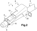
- the load carrier 1 includes, with reference to the figure 2 , a generally longitudinal arm 5 of which only part is shown.
- the arm 5 may have a round, oval, square section or any other shape.
- the arm is tubular in shape as shown in the figures.
- the load carrier 1 according to the invention may have one or two arms 5, preferably two longitudinal arms to which one or more elements (not shown) are usually attached allowing the load carrier to support a load.
- Each arm 5 is then fixed to the vehicle by a similar locking system.
- the load carrier 1 can then have general symmetry with respect to a median longitudinal plane.
- a free end 6 of the arm 5 is able to cooperate with the sleeve 3 secured to the structural element 2 of the vehicle.
- its dimensions allow its insertion inside the housing of the sleeve, under the rods 4a and 4b of the latter.
- the load carrier 1 comprises a locking system 7 installed at the end 6 of the longitudinal arm 5.
- the locking system 7 comprises a lever 8, one end 9 of which is mounted to rotate relative to the arm 5 around a transverse axis 10 carried by the end 6 of said arm 5.
- the locking system also comprises a helical spring 27, arranged between the lever and the arm, in particular between a substantially central part, along the longitudinal axis Y, of the lever 8 and the arm 5 and exerting a force on the lever 8.
- This spring is configured to exert a force substantially perpendicular to the longitudinal direction of the arm, here along the Z axis, tending to move the lever 8 away from the arm 5.
- the lever 8 comprises an upper face 12 having a notch 13 which will receive the rod 4a of the sleeve 3 when locking the load carrier 1.
- the lever 8 is thus movable between a high locking position in which it is spaced from the arm 5 and capable of cooperating with the sleeve 3 and a low unlocking position in which it is close to the arm 5. In the high position, the notch 13 receives rod 4a.
- the load carrier 1 comprises a blocking system 14 of the locking system.
- the blocking system 14 comprises a fixed part 15 mounted on the arm 5 and a movable part 16 rotatably mounted on the fixed part 15.
- the fixed part 15, partially shown Figure 3 is mounted to fit on the arm 5 and completely surrounds it. It is tightened and blocked on the arm, for example by a pin.
- the fixed part 15 comprises an internal wall 17 in contact with the arm and entirely surrounding it and an external wall 18 in contact with the movable part 16.
- the internal wall 17 of the fixed part 15 has a shape complementary to the shape of the arm. Thus, if the arm 5 has a square section, then the internal wall which surrounds it will also have a square section.
- the arm 5 is of cylindrical tubular shape and the internal wall 17 will also be of cylindrical shape.
- the external wall 18, for its part takes a cylindrical shape so that the mobile part can be mounted to rotate on it.
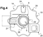
- the mobile part 16 is here in the form of a ring and it is rotatably mounted on the fixed part 15.
- the periphery 19 of the mobile part can include several indentations 20 to allow better handling of the mobile part 16 by the user .
- the movable part 16 is provided with a locking finger 21 extending in the direction of the lever, in the longitudinal direction of the arm.
- the function of the blocking finger 21 is to block the lever 8 in the high position, preventing it from approaching the arm 5 during vibrations or jolts during driving phases.
- the movable part 16 can be rotated between an unlocking position in which the movement of the lever 8 between its high and low positions is free, the locking finger not extending between the lever and the arm, and a locking position in which the blocking finger 21 extends between the lever 8 in the high position and the arm so as to block movement of the lever 8 from its high position to its low position.
- the locking finger 21 must be sufficiently close to the lever in the locking position to prevent the lever 8 from moving or prevent movement of the lever which would allow the rod 4a to come out of the notch 13.
- the locking finger 21 does not rest directly on the lever 8, but a clearance is provided to prevent the finger 21 from hitting against the lever 8 when it is moved to the locking position.
- the clearance must be less than the depth of the notch 13 to prevent the rod 4a from becoming detached from the notch 13 during a sudden movement of the vehicle and thus avoid unlocking the load carrier 1 from the sleeve 3.
- the locking finger 21 is also connected to the arm 5 by a support 26 pivoting around the arm and which here extends over the entire length of the locking finger measured in the longitudinal direction of the arm.
- the support 26 of the locking finger 21 has a cylindrical shape which does not extend over the entire periphery of the arm 5, but over half the periphery, or even less.
- support 26 is configured so that when the mobile part is in an unlocking position, the support does not extend, or very little, between the lever and the arm.
- Figure 6 shows that, when the movable part is in the locking position, an edge 26a of this support 26 abuts against the lever.
- This support 26 thus makes it possible on the one hand to block the finger 21 in the blocking position to facilitate its assembly in the blocking position and on the other hand to prevent the movement of the lever 8 from the high position to the low position from being limited by the support 26 as shown in the Figure 4 .
- the load carrier 1 is brought closer to the sleeve 3.
- the arm 5 of the load carrier 1 is then inserted inside the housing of the sleeve 3.
- the lever 8 is moved towards its lower position of unlocking by the rods 4a, 4b against the force exerted by the spring 27.
- the movable part must then be in the unlocking position shown Figure 4 so as not to hinder the movement of the lever 8.
- the arm 5 and the lever 8 are then inserted into the sleeve 3 until the rod 4a is housed in the notch 13, the lever 8 then rising to the high position locking under the action of spring 27 as shown figure 5 .
- the user will know the correct placement of the arm 5 when he hears a sound such as a click when the rod 4a enters the notch 13 and is held there by the force exerted by the spring.
- the end 6 of the arm 5 is then placed under the rod 4b, thus ensuring horizontal maintenance of the arm 5 inside the sleeve 3 without risk of tilting. In this position, the lever 8 in the high position is thus secured to the sleeve.
- a free end of the lever located next to the locking system 14 comprises a tongue 22 forming a stop extending along the locking finger 21, against or in the immediate vicinity thereof, when the movable part 16 is in the blocking position to facilitate the positioning of the blocking system 21 between the two positions.
- This tongue 22 extends here substantially perpendicular to the upper surface of the lever 12, in the direction of the arm and up to the height of the latter. In particular, as shown, the tongue is in contact with the arm in the lower position of the lever.
- the movable part 16 can then be pivoted from its unlocking position towards its blocking position until the edge 26a of the support 26 abuts against the tongue 22. The finger of locking is then correctly positioned between the arm and the lever.
- the user can start by moving the mobile part 16 of the blocking system 14 to place the finger 21 in the unlocking position ( fig. 4 ). Then, to separate the load carrier 1 from the sleeve 3, the user can exert pressure on the lever 8 to move it to the low position and release the rod 4a from the notch 13. The user can then exert traction on the arm 5 and the lever 8 to extract them from the sleeve 3.
- the load carrier 1 may comprise means 23 for blocking rotation of the movable part 16 relative to the fixed part 15 when the movable part is in the position of blocking, this in order to avoid any movement of the mobile part towards its unlocking position during the rolling of the vehicle, in particular under the effect of vibrations or sudden jolts during the rolling phase.
- the rotation blocking means 23 comprise a first fixing element 24 secured to the movable part 16, a second fixing element 25 secured here to a free end of the lever 8 the first 24 and second 25 elements fixing devices being located close to each other when the movable part is in the locking position, as shown Figure 6 .
- the first fixing element is an orifice 24 made through the movable part and the second fixing element is a tongue 25 pierced with an orifice.
- This pierced tongue 25 is integral with the lever, here integral with the tongue 22 serving as a stop, and extends perpendicular to the longitudinal direction of the arm, facing the orifice 24 of the movable part when the latter is in the blocking position ( fig. 6 ).
- the locking means 23 also comprise a third fixing element 28, from the movable part 16 to the lever 8 capable of securing the first 24 and second 25 fixing elements when the movable part 16 is in the locking position .
- the third fixing element 28 can be chosen from a padlock, an anti-theft device or a pin or any other element making it possible to secure the first 24 and second 25 fixing elements or making it possible to block the rotation of the movable part 16 relative to the arm 5
- the invention is however not limited to this embodiment and the first and second fixing elements could equally comprise a ring or a tongue provided with an orifice or a ring.
- the second fixing elements could also be integral with the fixed part.
- the rotation blocking means 23 may comprise a first latching element secured to the movable part, a second latching element secured to a free end of the lever 8 or of the fixed part 15, the first and second latching elements being engaged when the movable part 16 is in the locking position.
- the first and second latching elements are for example complementary male and female elements capable of cooperating. It may be a tongue cooperating with a slot or groove or even a finger cooperating with an orifice, etc. They can be configured to cooperate either in the longitudinal direction of the arm, or perpendicular to this direction. .
Landscapes
- Engineering & Computer Science (AREA)
- Mechanical Engineering (AREA)
- Lock And Its Accessories (AREA)
Applications Claiming Priority (1)
| Application Number | Priority Date | Filing Date | Title |
|---|---|---|---|
| FR2208219A FR3138796A1 (fr) | 2022-08-10 | 2022-08-10 | Porte-charge d’un véhicule automobile |
Publications (1)
| Publication Number | Publication Date |
|---|---|
| EP4321384A1 true EP4321384A1 (de) | 2024-02-14 |
Family
ID=83996437
Family Applications (1)
| Application Number | Title | Priority Date | Filing Date |
|---|---|---|---|
| EP23183989.5A Pending EP4321384A1 (de) | 2022-08-10 | 2023-07-06 | Lastenträger für ein kraftfahrzeug |
Country Status (2)
| Country | Link |
|---|---|
| EP (1) | EP4321384A1 (de) |
| FR (1) | FR3138796A1 (de) |
Citations (4)
| Publication number | Priority date | Publication date | Assignee | Title |
|---|---|---|---|---|
| WO1994005526A1 (de) * | 1992-09-08 | 1994-03-17 | Eberhard Tittel | Lastenträgeranordnung für den rückseitigen anbau eines lastenträgers an einem fahrzeug |
| US6334561B1 (en) * | 2000-05-31 | 2002-01-01 | Yakima Products, Inc. | Vehicle load carrier and clamping mechanism |
| WO2003039912A1 (en) * | 2001-11-06 | 2003-05-15 | Thule Sweden Ab | Coupling device for a load carrier |
| FR2867120A1 (fr) | 2004-03-02 | 2005-09-09 | Renault Sas | Porte-charge destine a equiper l'arriere d'un vehicule automobile |
-
2022
- 2022-08-10 FR FR2208219A patent/FR3138796A1/fr active Pending
-
2023
- 2023-07-06 EP EP23183989.5A patent/EP4321384A1/de active Pending
Patent Citations (4)
| Publication number | Priority date | Publication date | Assignee | Title |
|---|---|---|---|---|
| WO1994005526A1 (de) * | 1992-09-08 | 1994-03-17 | Eberhard Tittel | Lastenträgeranordnung für den rückseitigen anbau eines lastenträgers an einem fahrzeug |
| US6334561B1 (en) * | 2000-05-31 | 2002-01-01 | Yakima Products, Inc. | Vehicle load carrier and clamping mechanism |
| WO2003039912A1 (en) * | 2001-11-06 | 2003-05-15 | Thule Sweden Ab | Coupling device for a load carrier |
| FR2867120A1 (fr) | 2004-03-02 | 2005-09-09 | Renault Sas | Porte-charge destine a equiper l'arriere d'un vehicule automobile |
Also Published As
| Publication number | Publication date |
|---|---|
| FR3138796A1 (fr) | 2024-02-16 |
Similar Documents
| Publication | Publication Date | Title |
|---|---|---|
| FR2749232A1 (fr) | Dispositif pour la fixation pivotante d'ossatures de dossiers de sieges dans un vehicule | |
| EP1222090A1 (de) | Auf einem kraftfahrzeug anzubringende kindersicherungseinrichtung | |
| FR2651470A1 (fr) | Porte-cycle destine a equiper un vehicule. | |
| EP4321384A1 (de) | Lastenträger für ein kraftfahrzeug | |
| FR2990168A1 (fr) | Siege, notamment pour vehicule automobile | |
| WO2013045798A1 (fr) | Dispositif de fixation d'une barre de toit d'un vehicule automobile et agencement de barres de toit assemblees via un tel dispositif suivant plusieurs configurations | |
| EP0771719B1 (de) | Vorrichtung zum Verstauen eines Reserverades unter dem Boden eines Kraftfahrzeuges,enthält ausserdem Mittel zum Befestigen eines Aufbewahrungsbehälters,insbesondere für einen Wagenheber | |
| EP1122135B1 (de) | Kraftfahrzeug- Rücksitzbank, ihre Gurtschlösser mit veränderbarer Einhakposition | |
| FR2974326A1 (fr) | Systeme de connexion pour la fixation d'un dispositif de portage | |
| FR2800337A1 (fr) | Systeme d'arrimage d'objets a l'interieur d'un vehicule, et navette d'arrimage correspondante | |
| EP3124328B1 (de) | Dachlastenträger | |
| EP1750981B1 (de) | Befestigungsvorrichtung für kraftfahrzeugsicherheitsgurtverschlussschnalle und damit versehener sitz | |
| FR2730672A1 (fr) | Dispositif de remorquage d'un vehicule automobile | |
| FR2832105A1 (fr) | Siege de vehicule comprenant un dispositif d'assistance et vehicule equipe d'un tel siege | |
| FR2807366A1 (fr) | Dispositif de verrouillage a billes notamment pour l'ancrage d'un siege sur le plancher d'un vehicule automobile | |
| FR2945778A1 (fr) | Dispositif de protection visant a retenir un passager sur un siege de vehicule automobile et siege de vehicule automobile associe | |
| WO2017046527A1 (fr) | Dispositif de verrouillage bi-positions d'un dossier de siege arriere de vehicule automobile | |
| FR2599701A3 (fr) | Vehicules a deux roues avec dispositif de blocage d'un objet en general, et en particulier d'un casque de protection, sur la structure de ce vehicule | |
| FR2706409A1 (fr) | Dispositif d'accrochage réversible d'un siège sur un plancher de véhicule automobile. | |
| EP1827923A1 (de) | Verstellbare schliesshakenkörper für sicherheitsgurt | |
| EP1776259A1 (de) | Rückhalteanordnung in einem kraftfahrzeug | |
| WO2023144010A1 (fr) | Dispositif porte-vélo pour autocar | |
| FR3019098A1 (fr) | Antivol tete d'attelage | |
| FR2943010A1 (fr) | Systeme d'attache de securite pour vehicule equipe d'un plancher adapte. | |
| EP2121377B1 (de) | Kippvorrichtung für eine sitzlehne |
Legal Events
| Date | Code | Title | Description |
|---|---|---|---|
| PUAI | Public reference made under article 153(3) epc to a published international application that has entered the european phase |
Free format text: ORIGINAL CODE: 0009012 |
|
| STAA | Information on the status of an ep patent application or granted ep patent |
Free format text: STATUS: THE APPLICATION HAS BEEN PUBLISHED |
|
| AK | Designated contracting states |
Kind code of ref document: A1 Designated state(s): AL AT BE BG CH CY CZ DE DK EE ES FI FR GB GR HR HU IE IS IT LI LT LU LV MC ME MK MT NL NO PL PT RO RS SE SI SK SM TR |