EP1107883B1 - Halterungselement und halterung für starre leitungen in einem fahrzeug - Google Patents
Halterungselement und halterung für starre leitungen in einem fahrzeug Download PDFInfo
- Publication number
- EP1107883B1 EP1107883B1 EP99942799A EP99942799A EP1107883B1 EP 1107883 B1 EP1107883 B1 EP 1107883B1 EP 99942799 A EP99942799 A EP 99942799A EP 99942799 A EP99942799 A EP 99942799A EP 1107883 B1 EP1107883 B1 EP 1107883B1
- Authority
- EP
- European Patent Office
- Prior art keywords
- pipe
- receptacle
- securing element
- securing
- parts
- Prior art date
- Legal status (The legal status is an assumption and is not a legal conclusion. Google has not performed a legal analysis and makes no representation as to the accuracy of the status listed.)
- Expired - Lifetime
Links
- 239000004033 plastic Substances 0.000 claims description 7
- 239000000463 material Substances 0.000 claims description 4
- 239000013013 elastic material Substances 0.000 claims description 3
- 239000003507 refrigerant Substances 0.000 description 13
- 238000004378 air conditioning Methods 0.000 description 6
- 238000013016 damping Methods 0.000 description 4
- 238000004519 manufacturing process Methods 0.000 description 3
- 238000010276 construction Methods 0.000 description 2
- 230000008878 coupling Effects 0.000 description 2
- 238000010168 coupling process Methods 0.000 description 2
- 238000005859 coupling reaction Methods 0.000 description 2
- 229920001971 elastomer Polymers 0.000 description 2
- 238000003780 insertion Methods 0.000 description 2
- 230000037431 insertion Effects 0.000 description 2
- 239000004035 construction material Substances 0.000 description 1
- 230000000694 effects Effects 0.000 description 1
- 239000000806 elastomer Substances 0.000 description 1
- 238000000034 method Methods 0.000 description 1
- 229920000728 polyester Polymers 0.000 description 1
- 238000003825 pressing Methods 0.000 description 1
- 238000011144 upstream manufacturing Methods 0.000 description 1
- 239000013585 weight reducing agent Substances 0.000 description 1
Images

Classifications
-
- F—MECHANICAL ENGINEERING; LIGHTING; HEATING; WEAPONS; BLASTING
- F16—ENGINEERING ELEMENTS AND UNITS; GENERAL MEASURES FOR PRODUCING AND MAINTAINING EFFECTIVE FUNCTIONING OF MACHINES OR INSTALLATIONS; THERMAL INSULATION IN GENERAL
- F16L—PIPES; JOINTS OR FITTINGS FOR PIPES; SUPPORTS FOR PIPES, CABLES OR PROTECTIVE TUBING; MEANS FOR THERMAL INSULATION IN GENERAL
- F16L3/00—Supports for pipes, cables or protective tubing, e.g. hangers, holders, clamps, cleats, clips, brackets
- F16L3/08—Supports for pipes, cables or protective tubing, e.g. hangers, holders, clamps, cleats, clips, brackets substantially surrounding the pipe, cable or protective tubing
- F16L3/10—Supports for pipes, cables or protective tubing, e.g. hangers, holders, clamps, cleats, clips, brackets substantially surrounding the pipe, cable or protective tubing divided, i.e. with two members engaging the pipe, cable or protective tubing
- F16L3/1075—Supports for pipes, cables or protective tubing, e.g. hangers, holders, clamps, cleats, clips, brackets substantially surrounding the pipe, cable or protective tubing divided, i.e. with two members engaging the pipe, cable or protective tubing with two members, the two members being joined with a hinge on one side and fastened together on the other side
-
- F—MECHANICAL ENGINEERING; LIGHTING; HEATING; WEAPONS; BLASTING
- F16—ENGINEERING ELEMENTS AND UNITS; GENERAL MEASURES FOR PRODUCING AND MAINTAINING EFFECTIVE FUNCTIONING OF MACHINES OR INSTALLATIONS; THERMAL INSULATION IN GENERAL
- F16L—PIPES; JOINTS OR FITTINGS FOR PIPES; SUPPORTS FOR PIPES, CABLES OR PROTECTIVE TUBING; MEANS FOR THERMAL INSULATION IN GENERAL
- F16L3/00—Supports for pipes, cables or protective tubing, e.g. hangers, holders, clamps, cleats, clips, brackets
- F16L3/08—Supports for pipes, cables or protective tubing, e.g. hangers, holders, clamps, cleats, clips, brackets substantially surrounding the pipe, cable or protective tubing
- F16L3/12—Supports for pipes, cables or protective tubing, e.g. hangers, holders, clamps, cleats, clips, brackets substantially surrounding the pipe, cable or protective tubing comprising a member substantially surrounding the pipe, cable or protective tubing
- F16L3/13—Supports for pipes, cables or protective tubing, e.g. hangers, holders, clamps, cleats, clips, brackets substantially surrounding the pipe, cable or protective tubing comprising a member substantially surrounding the pipe, cable or protective tubing and engaging it by snap action
Definitions
- the invention relates to a mounting element and a mounting for rigid lines in a vehicle, in particular the lines of an air conditioning system.
- Document FR-A-2 704 027 discloses a Bracket element or a bracket according to the The preamble of claim 1 and 10 respectively.
- the respective clamp can be provided with a rubber insert, the one balancing effect with respect to a relative movement, for example between the attached to the vehicle body part and the clamp on a vehicle component attached line, and thus has a given by the running engine absorbs dynamic loads.
- Such clamps are also used to hold the Refrigerant lines of an air conditioning system installed in a vehicle are used.
- the air conditioning refrigerant circuit is between a condenser and a Expansion valve a refrigerant pressure line and between the expansion valve and a refrigerant suction line upstream of the condenser arranged, the compressor being connected to the motor and thus Motor movements on the compressor and the suction line to their holder a vehicle component not affected by the engine movement can be forwarded.
- the brackets have next to the above motion damping function also a noise damping function because of Compressor and also the noise flowing in the piping refrigerant disturbing noises generate the respective line on the bracket and thus on the vehicle be transmitted.
- Plastic double clamps are also known, with which parallel arranged lines can be determined. The same occur in these problems described.
- DE 195 46 086 A1 describes a multiple clamp for laying cables a receiving part and brackets for the lines known that a bracket part for additional arrangement of at least one line in a second Arrangement level with a mounting device for the line.
- the Bracket device is made of a trough-shaped on the bracket part Contact surface for the line and two molded on the bracket part, radially on the line directed clamping legs formed, which hold the line on the contact surface.
- the mounting element according to the invention is made of a fastening part Fixing on a vehicle body part and a receptacle for fixing the line formed, in the receptacle radially inward and at a distance from each other arranged clamping projections designed for pressure-elastic contact on the line are.
- This limited to the clamping projections elastic system of the recording the line by which this is defined in the recording enables a Largest decoupling of the mounting elements from the dynamic and acoustic exposure of the line to be held by the motor or flowing refrigerant so that the pipe movements and the noise are not be transferred to the vehicle body part.
- the holding element is preferably formed in one piece and consists of a elastic material with a low temperature coefficient. So that's it Holding the line independent of temperature loads and - fluctuations caused by the flowing refrigerant and when operating the air conditioning system the pipe cooled by this on the one hand and the engine heat on the other occur.
- the elastic construction material HYTREL is a suitable material Polyester elastomer from Du Pont in an excellent way.
- the clamping projections can be axially aligned ribs through their Condition, i.e. length, thickness, number and material, but especially by their number can influence the degree of decoupling. It has been shown that by a coaxially arranged ribs at a distance of 45 ° inside the receptacle sufficient decoupling can be ensured.
- the receptacle can be divided in two along its axis and the two parts can by one Guiding hinge arranged parallel to the axis can be connected to one another be so that the line is embedded in one part and through the other, transverse to Axial part pivotable via the line elastically against the clamping projections pressed and can thus be clamped elastically in the receptacle. You can do this in turn, locking elements can be attached to both parts, which the parts against Fix the clamping resistor together.
- This version provides a quick coupling with the task Damping properties through which the assembly time can be reduced.
- the receptacle can also be designed in the form of an open ring forms two legs, between which a gap is formed on the line insertion side. Through this gap, the line can easily in the recording and against Clamping protrusions pressed and fixed in this pressure-elastic. This too Execution provides a quick coupling with the task Damping properties. To facilitate the impressions, the free Be ends of the legs with radially inwardly directed chamfers. This version makes it easier - just like the previously described version Assembly and disassembly of the pipe to be held.
- the mounting element can advantageously with a fastening screw on the Fastening part on the respective vehicle body part can be designed to be fixable, whereby for the fastening screw at least one slot hole in the Fastening part is introduced or molded in order to compensate for manufacturing tolerances between the components.
- the holder for rigid lines according to the invention is made of a fastening part and formed a plurality of support elements according to the invention arranged on this, so that on this several lines, but especially the refrigerant pressure line and the refrigerant suction line of an air conditioner can be held, preferably in a parallel orientation.
- This holder is preferably in one piece trained, whereby the manufacturing and assembly costs are significantly reduced.
- the bracket can be designed so that it has a line with an angled Area. For this, it has at least two mounting elements, one of which is provided in the angled pipe area. Around Compensate manufacturing tolerances and thus avoid tension in the bracket can, is the bracket element provided for the angled pipe area in the plane defined by this and the straight line area transverse to Axis of its inclusion on the mounting part slidably arranged.
- A can Serve slide rail formed transversely to the axis of the receptacle on the fastening part.
- This holder is preferably made of a plastic with a small Temperature coefficients, especially the elastic construction plastic HYTREL from Du Pont, executed so that the object of the invention Decoupling of the vehicle from the dynamic and acoustic loads is ensured for each of the lines to be held. Except for the above bracket element described it can be integrally formed.
- the low temperature coefficient of the material mentioned ensures that this Decoupling even with very different line and engine compartment temperatures given is.
- This bracket is a compact bracket for multiple lines, with one Assembly and disassembly of the lines is facilitated, in particular one one-piece design is associated with a cost and weight reduction and also contributes to assembly process security.
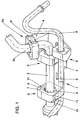
- Fig. 1 shows a holder 1 made of HYTREL, an elastic construction plastic with a low temperature coefficient for two refrigerant lines 2 and 3 one Air conditioning (not shown) in a passenger car.
- the refrigerant pressure line 2 is between the condenser of the air conditioner and one Expansion valve arranged and the refrigerant suction line 3 between the Expansion valve and the air conditioning compressor. Both lines 2 and 3 run parallel in the area of the holder 1, the refrigerant suction line 3 also has an angled line area 3a in the mounting area.
- the bracket 1 is intended for arrangement on a cover plate formed between the longitudinal members and has a fastening part 4 with two slots 5 for screwing to the Cover plate and a plurality of mounting elements 6 and a mounting element 6a, also made of HYTREL.
- the support elements 6 are integral and the mounting element 6a is connected to the fastening part 4 via a prism guide P. connected and each have a receptacle 7 for the respective line 2 or 3.
- Das Bracket 6a is through the prism guide P and the trained in it Slide rail transverse to the axis A of its receptacle 7 (Fig. 2a, 2b) and parallel to the line 3 or in the level determined by line 3 and its line area 3a Fastening part 4 slidably arranged.
- receptacle 7 In the receptacle 7 are radially inward directed and spaced clamping ribs 8 formed at closed receptacle 7 are pressed elastically on the respective line 2 or 3 and center them in the holder 7.
- the recordings 7 are on the Adjusted the diameter of the line 1 or 2 to be held.
- the mounting elements 6 and the mounting element 6a are in the area of the receptacle 7 divided in two along its axis, and the two parts 9 and 10 are by one Film hinge 11 connected to each other.
- Part 9 is on the film hinge 11th facing away from the receptacle 7, a locking lug 12 is formed, which in one with this corresponding locking recess 13 (Fig. 2a and 2b, shown in dashed lines) intervenes.
- the locking elements 12 and 13 fix the two parts 9 and 10 to each other and also absorb the clamping forces that occur.
- a holding element 6 (6a corresponding) is closed and opened state shown. It can be seen that the parts 9 and 10 except the Locking elements 12 and 13 on the film hinge side each have a locking element 14 or 15 have an additional lateral locking of the two parts 9 and 10th sure.
- a line 2 or 3 is installed in a simple manner by pushing it in the same in the part 9 of each intended for the respective line 2 or 3 Bracket element 6 and 6a (Fig. 2b) and subsequent pivoting of the respective Part 10 via line 2 or 3 and pressing until the locking elements lock 12 and 13.
- the clamping ribs 8 and the areas of parts 9 and 10 where the Clamping ribs 8 are formed, are elastically compressed so that the held line 2 or 3 dynamically and acoustically largely decoupled from the respective bracket element 6 and 6a or the bracket 1 is fixed.
- a Disassembly is carried out in the same simple way by loosening the locking connection 12/13 and pulling out line 2 or 3.
- FIG. 3 is a one-piece with a mounting member 15 mounting member 21, also made of HYTREL, shown.
- This has two receptacles 16 forming legs 17 and 18 with clamping ribs 19, between which a gap 20 for Inserting a line 2 or 3 is formed at the free ends of the legs 17th and 18, insertion slopes 17a and 18a are formed.
- the respective line 2 or 3 is simply pressed between the legs 17 and 18 until they are between the clamping ribs 19 is fixed by clamping
Landscapes
- Engineering & Computer Science (AREA)
- General Engineering & Computer Science (AREA)
- Mechanical Engineering (AREA)
- Supports For Pipes And Cables (AREA)
- Air-Conditioning For Vehicles (AREA)
Description
- Fig. 1.
- eine erfindungsgemäße Halterung für zwei starre Leitungen in einer perspektivischen Darstellung,
- Fig. 2a.
- ein Halterungselement in einer axialen Sicht in geschlossenem Zustand,
- Fig. 2b.
- dieses Halterungselement in geöffnetem Zustand und
- Fig. 3.
- eine andere Ausführungsform eines Halterungselementes.
Claims (16)
- Halterungselement für eine starre Leitung in einem Fahrzeug, mit einem Befestigungsteil und mit einer Aufnahme zum Fixieren der Leitung, dadurch gekennzeichnet, daß in der Aufnahme (7; 16) radial nach innen gerichtete und im Abstand zueinander angeordnete Klemmvorsprünge (8; 19) zur druckelastischen Anlage an der zwischen diesen aufgenommenen Leitung (2; 3) ausgebildet sind.
- Halterungselement nach Anspruch 1, dadurch gekennzeichnet, daß dieses (21) einstückig ist und aus einem elastischen Werkstoff mit einem geringen Temperaturkoeffizienten besteht
- Halterungselement nach Anspruch 2, dadurch gekennzeichnet, daß der Werkstoff der elastische Konstruktionskunststoff HYTREL ist.
- Halterungselement nach Anspruch 1, dadurch gekennzeichnet, daß die Klemmvorsprünge axial ausgerichtete Klemmrippen (8, 19) sind.
- Halterungselement nach Anspruch 1 oder 2, dadurch gekennzeichnet, daß die Aufnahme (7; 16) längs ihrer Achse (A) zweigeteilt ist und die beiden Teile (9; 10) durch ein parallel zur Achse (A) angeordnetes Filmschamier (11) miteinander verbunden sind.
- Halterungselement nach Anspruch 5, dadurch gekennzeichnet, daß die beiden Teile (9; 10) Rastelemente (12; 13) aufweisen, mit denen die Teile (9; 10) unter Aufnahme der beim Umgreifen der jeweiligen Leitung (2; 3) auftretenden Klemmkräfte aneinander festlegbar sind.
- Halterungselement nach Anspruch 1 oder 2, dadurch gekennzeichnet, daß dieses (21) jeweils zwei die Aufnahme (16) bildende Schenkel (17, 18) aufweist, zwischen denen leitungseinführseitig ein Spalt (20) zum Einführen der Leitung (2; 3) ausgebildet ist.
- Halterungselement nach Anspruch 7, dadurch gekennzeichnet, daß die freien Enden der Schenkel (17, 18) mit Einführschrägen (17a, 18a) für die Leitung (2; 3) versehen sind.
- Halterungselement nach Anspruch 1, dadurch gekennzeichnet, daß das Befestigungsteil (415) durch eine Schraubverbindung (S) an einem Fahrzeugaufbauteil festlegbar ist
- Halterung für starre Leitungen in einem Fahrzeug, mit einem Befestigungsteil und mehreren Halterungselementen für die Leitungen, dadurch gekennzeichnet, daß die Halterungselmente (6; 21) jeweils eine Aufnahme (7; 16) zum Fixieren der jeweiligen Leitung (2; 3) aufweisen, und daß in der Aufnahme (7; 16) radial nach innen gerichtete und im Abstand zueinander angeordnete Klemmvorsprünge (8; 19) zur druckelastischen Anlage an der zwischen diesen aufgenommenen Leitung (2; 3) ausgebildet sind.
- Halterung nach Anspruch 10, dadurch gekennzeichnet, daß das jeweilige Halterungselement (6) im Bereich der Aufnahme (7) in axialer Richtung zweigeteilt ist und die beiden Teile (9; 10) durch ein Filmschamier (11) miteinander verbunden sind und Rastelemente (12; 13) zum Aneinanderfestlegen unter Aufnahme der auftretenden Klemmkräfte aufweisen, oder daß das jeweilige Halterungselement (21) jeweils zwei die Aufnahme (16) bildende Schenkel (17, 18) aufweist, zwischen denen leitungseinführseitig ein Spalt (20) zum Einführen der Leitung (2; 3) ausgebildet ist.
- Halterung nach Anspruch 10, dadurch gekennzeichnet, daß diese einstückig ausgebildet ist.
- Halterung nach Anspruch 10 oder 11, dadurch gekennzeichnet, daß zur Festlegung einer Leitung (3) mit einem abgewinkelten Leitungsbereich (3a) ein Halterungselement (6a) für diesen (3a) vorgesehen ist, und daß dieses Halterungselement (6a) in der durch die Leitung (3) und den abgewinkelten Leitungsbereich (3a) bestimmten Ebene quer zur Achse (A) seiner Aufnahme (7) verschiebbar am Befestigungsteil (4) angeordnet ist.
- Halterung nach Anspruch 13, dadurch gekennzeichnet, daß das Halterungselement (6a) an einer quer zur Achse (A) seiner Aufnahme (7) am Befestigungsteil (4) ausgebildeten Gleitschiene (P) angeordnet ist.
- Halterung nach einem der Ansprüche 10 bis 14, dadurch gekennzeichnet, daß diese aus einem elastischen Werkstoff mit einem geringen Temperaturkoeffizienten gebildet ist, vorzugsweise aus dem Kunststoff HYTREL.
- Halterung nach Anspruch 10, dadurch gekennzeichnet, daß das Befestigungsteil (4; 15) durch eine Schraubverbindung (S) an einem Fahrzeugaufbauteil festlegbar ist.
Applications Claiming Priority (3)
| Application Number | Priority Date | Filing Date | Title |
|---|---|---|---|
| DE19840136A DE19840136A1 (de) | 1998-09-03 | 1998-09-03 | Halterungselement und Halterung für starre Leitungen in einem Fahrzeug |
| DE19840136 | 1998-09-03 | ||
| PCT/EP1999/005319 WO2000013941A1 (de) | 1998-09-03 | 1999-07-26 | Halterungselement und halterung für starre leitungen in einem fahrzeug |
Publications (2)
| Publication Number | Publication Date |
|---|---|
| EP1107883A1 EP1107883A1 (de) | 2001-06-20 |
| EP1107883B1 true EP1107883B1 (de) | 2004-05-19 |
Family
ID=7879664
Family Applications (1)
| Application Number | Title | Priority Date | Filing Date |
|---|---|---|---|
| EP99942799A Expired - Lifetime EP1107883B1 (de) | 1998-09-03 | 1999-07-26 | Halterungselement und halterung für starre leitungen in einem fahrzeug |
Country Status (7)
| Country | Link |
|---|---|
| US (1) | US6676091B2 (de) |
| EP (1) | EP1107883B1 (de) |
| JP (1) | JP4588881B2 (de) |
| CN (1) | CN1288009C (de) |
| DE (2) | DE19840136A1 (de) |
| ES (1) | ES2221428T3 (de) |
| WO (1) | WO2000013941A1 (de) |
Families Citing this family (36)
| Publication number | Priority date | Publication date | Assignee | Title |
|---|---|---|---|---|
| DE10214300A1 (de) * | 2002-03-28 | 2003-10-16 | Murrplastik Systemtechnik Gmbh | Kabeldurchführungsleiste |
| US7207527B2 (en) * | 2003-04-14 | 2007-04-24 | Klo-Shure, Inc. | Clevis hanger assembly and pipe insulation coupling |
| US20060145321A1 (en) * | 2004-12-30 | 2006-07-06 | Rohm And Haas Electronic Materials Llc | Microcomponent holder and method for manufacture thereof |
| WO2007126349A1 (en) * | 2006-04-28 | 2007-11-08 | Telefonaktiebolaget Lm Ericsson (Publ) | A cable suspension device |
| DE102006037443A1 (de) * | 2006-08-09 | 2008-02-14 | Behr Gmbh & Co. Kg | Kraftfahrzeug-Klimaanlagenanordnung |
| US8328458B2 (en) * | 2007-07-20 | 2012-12-11 | Twin Bay Medical, Inc. | Sanitary clamp |
| US8328457B2 (en) * | 2007-07-20 | 2012-12-11 | Twin Bay Medical, Inc. | Sanitary clamp |
| KR101375080B1 (ko) * | 2007-08-30 | 2014-03-17 | 한라비스테온공조 주식회사 | 차량용 파이프 고정구조 |
| DE102009016283B4 (de) * | 2008-04-24 | 2024-12-05 | Schaeffler Technologies AG & Co. KG | Hydrauliksystem |
| US8375798B2 (en) * | 2008-06-17 | 2013-02-19 | Robert C. Anderson | External pressure measuring device |
| US8381667B2 (en) * | 2009-02-13 | 2013-02-26 | Alstom Technology Ltd | Adjustable, multiple splash plate liquor guns |
| US8439317B2 (en) * | 2009-02-27 | 2013-05-14 | Franklin Fastener Company | Grommeted clamp assembly |
| US8973889B2 (en) * | 2009-03-13 | 2015-03-10 | Saint-Gobain Performance Plastics Corporation | Tube clamp |
| US8726468B2 (en) | 2009-03-18 | 2014-05-20 | Hellermanntyton Corporation | Bundle tie with head dampener |
| US9605782B2 (en) | 2009-04-02 | 2017-03-28 | Saint-Gobain Performance Plastics Corporation | Sanitary retainer |
| WO2012040415A2 (en) * | 2010-09-22 | 2012-03-29 | Trico Products Corporation | Beam blade windshield wiper assembly having a fluid manifold mounting system |
| JP5772444B2 (ja) * | 2011-09-22 | 2015-09-02 | 住友電装株式会社 | クランプ |
| US8973880B2 (en) | 2012-01-30 | 2015-03-10 | Polaris Industries Inc. | Clamp |
| FR2995389B1 (fr) * | 2012-09-13 | 2017-10-20 | Alstom Transport Sa | Dispositif de climatisation d'air, notamment pour un vehicule ferroviaire |
| CN103335170B (zh) * | 2013-06-21 | 2015-05-27 | 浙江奇峰泵业有限公司 | 一种气管固定装置 |
| DE102013217163A1 (de) * | 2013-08-28 | 2015-03-05 | Jungheinrich Aktiengesellschaft | Schlauchbefestigungseinrichtung zur Fixierung von Schläuchen an einem Untergrund, insbesondere an einem Hubgerüst eines Flurförderzeugs |
| CN103660857A (zh) * | 2013-11-13 | 2014-03-26 | 上海酷铠制冷设备有限公司 | 一种车载制冷装置及冷藏运输装置 |
| DE102013113224A1 (de) * | 2013-11-29 | 2015-06-03 | Poppe GmbH | Elastomerer Leitungsdämpfer |
| JP6294065B2 (ja) * | 2013-12-09 | 2018-03-14 | シャープ株式会社 | 空気調和機 |
| US9548597B2 (en) * | 2014-06-13 | 2017-01-17 | Ortronics, Inc. | Cable management assemblies and associated methods |
| US10215308B2 (en) * | 2016-11-11 | 2019-02-26 | Hap Technologies Co. | Pipe securing apparatus |
| US20200171432A1 (en) | 2017-05-30 | 2020-06-04 | Universidad De Los Andes | A filtering apparatus and method for treating polluted air in indoor spaces |
| EP3899338A4 (de) * | 2018-12-18 | 2022-09-07 | Saint-Augustin Canada Electric Inc. | Spannvorrichtungen |
| US11536395B2 (en) * | 2020-02-17 | 2022-12-27 | Verathon Inc. | Cable support clip for medical device workstation |
| CN111577991B (zh) * | 2020-05-12 | 2021-11-09 | 淄博美玲汽车配件有限公司 | 一种车辆管路安装支架结构 |
| JP7294276B2 (ja) * | 2020-08-26 | 2023-06-20 | Jfeスチール株式会社 | 保持装置および可動部材の取り付け方法 |
| KR20220049908A (ko) | 2020-10-15 | 2022-04-22 | 삼성전자주식회사 | 공기조화기 |
| US12184152B1 (en) * | 2021-01-11 | 2024-12-31 | Hydro-Gear Limited Partnership | Vibration damping apparatus for mounting an electric actuator on a hydraulic drive |
| US12326209B2 (en) * | 2022-04-12 | 2025-06-10 | Dixon Valve & Coupling Company, Llc | Tube and pipe hanger |
| FR3152549B1 (fr) * | 2023-09-05 | 2025-07-18 | Francois Inglese | Dispositif de fixation d’au moins un tube contre une tige, par exemple une tige filetée ou une tige d’un ferraillage de béton armée |
| DE102023208908A1 (de) | 2023-09-13 | 2025-03-13 | Volkswagen Aktiengesellschaft | Anordnung aus mindestens einem Funktionsteilhalter und mindestens einer Rohrleitung zur Montage an einem Kraftfahrzeug sowie Verfahren zu deren Herstellung |
Family Cites Families (34)
| Publication number | Priority date | Publication date | Assignee | Title |
|---|---|---|---|---|
| US2923760A (en) * | 1956-11-15 | 1960-02-02 | Famely Max | Retaining clamps |
| US3606218A (en) * | 1969-03-21 | 1971-09-20 | Gen Dynamics Corp | Sound and vibration isolation support |
| US3684223A (en) * | 1970-10-20 | 1972-08-15 | Duane D Logsdon | Pipe clamp |
| US4172578A (en) * | 1978-03-16 | 1979-10-30 | Indian Head Inc. | Device for clamping conduit |
| EP0010559B1 (de) * | 1978-11-01 | 1982-12-22 | BICC Public Limited Company | Rohr- und Kabelklemme |
| JPS5733263Y2 (de) * | 1979-02-07 | 1982-07-22 | ||
| US4260123A (en) * | 1979-11-23 | 1981-04-07 | Ismert Joseph P | Tubing hanger |
| DE3025601C2 (de) * | 1980-07-05 | 1982-04-29 | Daimler-Benz Ag, 7000 Stuttgart | Anordnung zum geräuscharmen Aufhängen von langgestreckten Bauteilen, wie Rohren oder Schläuchen |
| US4431152A (en) * | 1981-12-10 | 1984-02-14 | Square D Company | Adjustable cable restraint assembly |
| JPS58106146U (ja) * | 1982-01-11 | 1983-07-19 | 株式会社ニフコ | 固定装置 |
| US4442994A (en) * | 1982-02-02 | 1984-04-17 | Logsdon Duane D | Pipe hanger capable of totally encircling a pipe |
| GB8421027D0 (en) * | 1984-08-17 | 1984-09-19 | Conoco Inc | Clamps for pipelines |
| FR2572488B1 (fr) * | 1984-10-25 | 1989-02-10 | Tabouy Christian | Collier monobloc pour la suspension de conduites |
| DE3705626A1 (de) * | 1987-02-21 | 1988-09-01 | Raymond A Fa | Montageeinheit zur befestigung von versorgungsleitungen an kraftfahrzeugen |
| DE3824197A1 (de) * | 1988-07-16 | 1990-01-18 | Theodor Stratmann | Rohrschelle |
| JPH02203230A (ja) * | 1989-01-31 | 1990-08-13 | Daikin Ind Ltd | 管内圧力変化検知変換器 |
| DE8908688U1 (de) * | 1989-07-18 | 1989-08-31 | Hydac Technology GmbH, 6603 Sulzbach | Blockschelle mit Längsrippen |
| JP2552191Y2 (ja) * | 1990-11-09 | 1997-10-27 | 株式会社東郷製作所 | 防振クランプ |
| US5067677A (en) * | 1990-12-14 | 1991-11-26 | Edward Miceli | Wire harness |
| DE4123754C2 (de) * | 1991-07-18 | 1993-11-04 | Bettermann Obo Ohg | Kabelschelle |
| FR2704027B1 (fr) | 1993-04-13 | 1995-12-01 | Trw Carr France Sa | Elément de retenue, notamment pour carroseries de véhicules automobiles. |
| DE9403291U1 (de) * | 1994-02-28 | 1994-05-05 | Hermann Kleinhuis GmbH & Co KG, 58507 Lüdenscheid | Dachleitungshalter für elektrische Leitungen |
| DE4411221A1 (de) * | 1994-03-31 | 1995-10-05 | Hilti Ag | Rohrschellenverschluss |
| DE4411220A1 (de) * | 1994-03-31 | 1995-10-05 | Hilti Ag | Rohrmanschette |
| US5492671A (en) * | 1994-12-20 | 1996-02-20 | Zimmer, Inc. | Sterilization case and method of sterilization |
| DE19546086A1 (de) * | 1995-12-11 | 1996-09-19 | Daimler Benz Ag | Mehrfachschelle zum Verlegen von Leitungen |
| NO305334B1 (no) * | 1996-04-01 | 1999-05-10 | Eilif Elvegaard | Klammeranordning for fastspenning av r°r e.l. |
| US5655673A (en) * | 1996-05-03 | 1997-08-12 | Robbins Industries Inc. | Large spice jar rack |
| US5772160A (en) * | 1996-09-19 | 1998-06-30 | Trw Inc. | Support bracket for releasable mounting to spaced tubes |
| US6244447B1 (en) * | 1997-04-22 | 2001-06-12 | Marcia A Frieze | Instrument bracket with resilient locking means for use with a sterilizable tray |
| US5830183A (en) * | 1997-06-30 | 1998-11-03 | Schneider (Usa) Inc | Clip device for vascular catheter |
| US6164604A (en) * | 1998-02-03 | 2000-12-26 | Oatey Co. | Pipe clamps |
| US6152412A (en) * | 1998-04-17 | 2000-11-28 | Greenfield Mfg. Co., Inc. | Suspension hanger |
| US5937604A (en) * | 1998-08-21 | 1999-08-17 | Bowron; Robert F. | Concrete form wall spacer |
-
1998
- 1998-09-03 DE DE19840136A patent/DE19840136A1/de not_active Withdrawn
-
1999
- 1999-07-26 CN CNB998101109A patent/CN1288009C/zh not_active Expired - Lifetime
- 1999-07-26 ES ES99942799T patent/ES2221428T3/es not_active Expired - Lifetime
- 1999-07-26 WO PCT/EP1999/005319 patent/WO2000013941A1/de not_active Ceased
- 1999-07-26 DE DE59909534T patent/DE59909534D1/de not_active Expired - Lifetime
- 1999-07-26 JP JP2000568715A patent/JP4588881B2/ja not_active Expired - Fee Related
- 1999-07-26 EP EP99942799A patent/EP1107883B1/de not_active Expired - Lifetime
-
2001
- 2001-03-01 US US09/797,285 patent/US6676091B2/en not_active Expired - Lifetime
Also Published As
| Publication number | Publication date |
|---|---|
| CN1288009C (zh) | 2006-12-06 |
| US20010008265A1 (en) | 2001-07-19 |
| CN1314852A (zh) | 2001-09-26 |
| JP4588881B2 (ja) | 2010-12-01 |
| DE59909534D1 (de) | 2004-06-24 |
| DE19840136A1 (de) | 2000-03-09 |
| JP2002524694A (ja) | 2002-08-06 |
| ES2221428T3 (es) | 2004-12-16 |
| US6676091B2 (en) | 2004-01-13 |
| WO2000013941A1 (de) | 2000-03-16 |
| EP1107883A1 (de) | 2001-06-20 |
Similar Documents
| Publication | Publication Date | Title |
|---|---|---|
| DE19840136A1 (de) | Halterungselement und Halterung für starre Leitungen in einem Fahrzeug | |
| EP1729388B1 (de) | Befestigungsvorrichtung für mehrere Leitungen | |
| EP2092216B1 (de) | Getriebegehäuse | |
| DE69723527T2 (de) | Halter für rohrförmige Komponenten | |
| DE69401402T2 (de) | Vorrichtung zum Montieren eines Rohres auf einem Träger | |
| DE19526934A1 (de) | Befestigungselement | |
| DE202009013150U1 (de) | Montagesystem für die Befestigung einer Stoßfängerverkleidung | |
| WO2012123206A1 (de) | Schwingungsdämpfende aufnahmevorrichtung | |
| DE102009005422A1 (de) | Clip | |
| DE10333000A1 (de) | Befestigungsmittel für einen Ölkühler | |
| DE102013102834A1 (de) | Halterung für einen Elektromotor, insbesondere in einem Fahrzeug | |
| DE10248948C5 (de) | Scheibenbremse, insbesondere für ein Nutzfahrzeug | |
| EP2380764B1 (de) | Windabweiser für KFZ-Dachöffnungen | |
| DE202009012422U1 (de) | Vorrichtung zur lagegenauen Montagepositionierung von mindestens zwei Bauteilen zueinander | |
| EP0943773A2 (de) | Positionierelement zur Ausrichtung von Karosserieteilen | |
| DE102009058815B4 (de) | Haltevorrichtung für Anbauteile von Fahrzeugen | |
| DE102020214025A1 (de) | Aufdachklimaanlage für Fahrzeuge | |
| DE10039679B4 (de) | Anordnung zur Befestigung eines Bauteils an einer Montageplatte | |
| DE102005055479A1 (de) | Luftfiltergehäuse | |
| DE202017100299U1 (de) | Haltevorrichtung zum Halten mindestens einer Leitung | |
| EP1111285B1 (de) | Halter | |
| DE102004005210A1 (de) | Filter, insbesondere Kraftfahrzeug-Ansaugfilter | |
| DE10114275A1 (de) | Halteelement für mehrere Aufnahmeteile wie Leitungen, Kabel oder dergleichen | |
| EP0801248B1 (de) | Befestigungsvorrichtung | |
| DE102007043320A1 (de) | Vorrichtung zur Dämpfung von Schwingungen sowie Verwendung der Vorrichtung |
Legal Events
| Date | Code | Title | Description |
|---|---|---|---|
| PUAI | Public reference made under article 153(3) epc to a published international application that has entered the european phase |
Free format text: ORIGINAL CODE: 0009012 |
|
| 17P | Request for examination filed |
Effective date: 20010403 |
|
| AK | Designated contracting states |
Kind code of ref document: A1 Designated state(s): AT BE CH CY DE DK ES FI FR GB GR IE IT LI LU MC NL PT SE |
|
| RIN1 | Information on inventor provided before grant (corrected) |
Inventor name: HAUER, MATTHIAS |
|
| GRAP | Despatch of communication of intention to grant a patent |
Free format text: ORIGINAL CODE: EPIDOSNIGR1 |
|
| GRAS | Grant fee paid |
Free format text: ORIGINAL CODE: EPIDOSNIGR3 |
|
| GRAA | (expected) grant |
Free format text: ORIGINAL CODE: 0009210 |
|
| AK | Designated contracting states |
Kind code of ref document: B1 Designated state(s): DE ES FR IT |
|
| PG25 | Lapsed in a contracting state [announced via postgrant information from national office to epo] |
Ref country code: IT Free format text: LAPSE BECAUSE OF FAILURE TO SUBMIT A TRANSLATION OF THE DESCRIPTION OR TO PAY THE FEE WITHIN THE PRE;WARNING: LAPSES OF ITALIAN PATENTS WITH EFFECTIVE DATE BEFORE 2007 MAY HAVE OCCURRED AT ANY TIME BEFORE 2007. THE CORRECT EFFECTIVE DATE MAY BE DIFFERENT FROM THE ONE RECORDED.SCRIBED TIME-LIMIT Effective date: 20040519 |
|
| REG | Reference to a national code |
Ref country code: IE Ref legal event code: FG4D Free format text: GERMAN |
|
| REF | Corresponds to: |
Ref document number: 59909534 Country of ref document: DE Date of ref document: 20040624 Kind code of ref document: P |
|
| REG | Reference to a national code |
Ref country code: ES Ref legal event code: FG2A Ref document number: 2221428 Country of ref document: ES Kind code of ref document: T3 |
|
| REG | Reference to a national code |
Ref country code: IE Ref legal event code: FD4D |
|
| ET | Fr: translation filed | ||
| PLBE | No opposition filed within time limit |
Free format text: ORIGINAL CODE: 0009261 |
|
| STAA | Information on the status of an ep patent application or granted ep patent |
Free format text: STATUS: NO OPPOSITION FILED WITHIN TIME LIMIT |
|
| 26N | No opposition filed |
Effective date: 20050222 |
|
| REG | Reference to a national code |
Ref country code: FR Ref legal event code: PLFP Year of fee payment: 17 |
|
| REG | Reference to a national code |
Ref country code: FR Ref legal event code: PLFP Year of fee payment: 18 |
|
| REG | Reference to a national code |
Ref country code: FR Ref legal event code: PLFP Year of fee payment: 19 |
|
| REG | Reference to a national code |
Ref country code: FR Ref legal event code: PLFP Year of fee payment: 20 |
|
| PGFP | Annual fee paid to national office [announced via postgrant information from national office to epo] |
Ref country code: FR Payment date: 20180726 Year of fee payment: 20 Ref country code: ES Payment date: 20180828 Year of fee payment: 20 Ref country code: DE Payment date: 20180731 Year of fee payment: 20 |
|
| REG | Reference to a national code |
Ref country code: DE Ref legal event code: R071 Ref document number: 59909534 Country of ref document: DE |
|
| REG | Reference to a national code |
Ref country code: ES Ref legal event code: FD2A Effective date: 20200904 |
|
| PG25 | Lapsed in a contracting state [announced via postgrant information from national office to epo] |
Ref country code: ES Free format text: LAPSE BECAUSE OF EXPIRATION OF PROTECTION Effective date: 20190727 |
|
| P01 | Opt-out of the competence of the unified patent court (upc) registered |
Effective date: 20230523 |