EP1107540A2 - Datenkommunikationsystem und Verfahren - Google Patents
Datenkommunikationsystem und Verfahren Download PDFInfo
- Publication number
- EP1107540A2 EP1107540A2 EP00310698A EP00310698A EP1107540A2 EP 1107540 A2 EP1107540 A2 EP 1107540A2 EP 00310698 A EP00310698 A EP 00310698A EP 00310698 A EP00310698 A EP 00310698A EP 1107540 A2 EP1107540 A2 EP 1107540A2
- Authority
- EP
- European Patent Office
- Prior art keywords
- communication network
- data
- application server
- wireless communication
- transmission
- Prior art date
- Legal status (The legal status is an assumption and is not a legal conclusion. Google has not performed a legal analysis and makes no representation as to the accuracy of the status listed.)
- Granted
Links
Images




Classifications
-
- H—ELECTRICITY
- H04—ELECTRIC COMMUNICATION TECHNIQUE
- H04L—TRANSMISSION OF DIGITAL INFORMATION, e.g. TELEGRAPHIC COMMUNICATION
- H04L47/00—Traffic control in data switching networks
- H04L47/10—Flow control; Congestion control
- H04L47/28—Flow control; Congestion control in relation to timing considerations
- H04L47/283—Flow control; Congestion control in relation to timing considerations in response to processing delays, e.g. caused by jitter or round trip time [RTT]
-
- H—ELECTRICITY
- H04—ELECTRIC COMMUNICATION TECHNIQUE
- H04L—TRANSMISSION OF DIGITAL INFORMATION, e.g. TELEGRAPHIC COMMUNICATION
- H04L12/00—Data switching networks
- H04L12/54—Store-and-forward switching systems
- H04L12/56—Packet switching systems
- H04L12/5691—Access to open networks; Ingress point selection, e.g. ISP selection
- H04L12/5692—Selection among different networks
-
- H—ELECTRICITY
- H04—ELECTRIC COMMUNICATION TECHNIQUE
- H04L—TRANSMISSION OF DIGITAL INFORMATION, e.g. TELEGRAPHIC COMMUNICATION
- H04L47/00—Traffic control in data switching networks
- H04L47/10—Flow control; Congestion control
-
- H—ELECTRICITY
- H04—ELECTRIC COMMUNICATION TECHNIQUE
- H04W—WIRELESS COMMUNICATION NETWORKS
- H04W28/00—Network traffic management; Network resource management
- H04W28/02—Traffic management, e.g. flow control or congestion control
- H04W28/0231—Traffic management, e.g. flow control or congestion control based on communication conditions
-
- H—ELECTRICITY
- H04—ELECTRIC COMMUNICATION TECHNIQUE
- H04W—WIRELESS COMMUNICATION NETWORKS
- H04W28/00—Network traffic management; Network resource management
- H04W28/02—Traffic management, e.g. flow control or congestion control
- H04W28/0273—Traffic management, e.g. flow control or congestion control adapting protocols for flow control or congestion control to wireless environment, e.g. adapting transmission control protocol [TCP]
-
- H—ELECTRICITY
- H04—ELECTRIC COMMUNICATION TECHNIQUE
- H04W—WIRELESS COMMUNICATION NETWORKS
- H04W8/00—Network data management
- H04W8/02—Processing of mobility data, e.g. registration information at HLR [Home Location Register] or VLR [Visitor Location Register]; Transfer of mobility data, e.g. between HLR, VLR or external networks
- H04W8/04—Registration at HLR or HSS [Home Subscriber Server]
Definitions
- the present invention relates to a data communication system that sends and receives data to or from an application server via a transmission line comprising one type of a wire communication network, a wireless communication network, and both a wire communication network and a wireless communication network. More particularly, the present invention relates to a data communication system and a data communication method not affected by transmission line characteristics.
- the user accesses the Internet from a data communication terminal in a variety of ways.
- the user accesses the Internet, in most cases, via a wire communication network such as a LAN (Local Area Network) in which terminals are connected by Ethernet or via a wire communication network in which telephone lines and modems are used.
- a wire communication network such as a LAN (Local Area Network) in which terminals are connected by Ethernet or via a wire communication network in which telephone lines and modems are used.
- LAN Local Area Network
- PHS Personal Handy Phone System
- PDC Personal Digital Cellular
- IP Internet Protocol
- layer that provides data communication terminals with the terminal-to-terminal data transfer function. It is requested to transmit data as effectively as possible on a transmission protocol hierarchy layer in the communication protocol hierarchy. For increased efficiency, many transmission protocols are proposed.
- a transmission protocol for accessing the Internet in a wire communication network is optimized for the characteristics of the configuration of a wire network in which a plurality of LANs are connected via routers.
- the protocol is designed for providing best performance in such a wire network.
- a transmission protocol for accessing the Internet in a wireless communication network is optimized for the characteristics of a wireless network that has a large data transmission delay and a narrow transmission bandwidth, so that the protocol is designed for providing best performance in such a network.
- a data communication terminal efficiently accesses the Internet using the same protocol via one of a wire communication network, a wireless communication network, and both a wire communication network and a wireless communication network in one of the following methods:
- the former (1) has a problem that increases the amount of memory resources of the data communication terminal, increases the terminal size, and therefore makes the terminal impractical.
- the latter (2) has a second problem that significantly decreases the throughput of the other, non-optimized communication network and therefore requires positive unit for suppressing the effect of the characteristics of the other communication network.
- RTT Round Trip Time
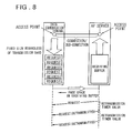
- FIG. 8 is a diagram showing the amount of the free space in the receiving buffer at the destination.
- a data communication terminal sends or receives data to or from an application server (AP server) using the same protocol via a transmission line over one of a wire communication network, a wireless communication network, and both a wire communication network and a wireless communication network
- AP server application server
- the amount of free space in the receiving buffer at the destination affects the transmission speed of the communication network and the processing speed of the destination terminal.
- the sending data communication terminal determines the sending buffer size based on the amount of free space of the receiving buffer of the destination AP server, the above-described first problem of allocating unnecessary memory resources arises if the communication network speed is lower than the processing speed of the destination terminal.
- FIG. 9 is a diagram showing the relation between the application server processing time and the retransmission time.
- the AP server processing time RTT
- the AP server processing time is closely associated with a transmission delay (or none) caused by data errors on the communication network and with the retransmission time (timer). Therefore, an improper retransmission timer value, if set, would result in an incorrect data-loss detection and an unnecessary retransmission of a packet or in an unnecessary suppression of packet retransmission, thus generating the second problem which decreases throughput significantly.
- a data communication system which sends or receives data to or from an application server using the same protocol via a transmission line comprising one type of a wire communication network, a wireless communication network, and both a wire communication network and a wireless communication network.
- the data communication system comprises a first table containing therein a relation among a service identifier of the application server, a destination address, a communication network type, and a processing time of the application server; and a retransmission timer setting unit which references the first table to find the processing time of the application server based on the service identifier, destination address, and communication network type during transmission or reception of data to or from the application server, and sets the time as a retransmission time.
- This formulation sets the retransmission timer properly and therefore reduces the possibility of unnecessary retransmission of packets due to an incorrect data-loss detection or the possibility of unnecessary suppression of transmission at retransmission time, significantly increasing throughput.
- the data communication system further comprises a radio status acquisition unit which acquires a radio wave strength of the wireless communication network and an error rate of data sent to or received from the wireless communication network from a wireless base station connected via a physical line; and a second table containing therein a relation among radio wave strength of the wireless communication network, error rate of data sent to or received from the communication network, the communication network type, and communication network transmission speeds, wherein the retransmission timer setting unit references the second table, calculates the transmission/reception time for each packet size based on the radio wave strength and the error rate acquired from the radio status acquisition unit, and sets a sum of the processing time of the application server and the calculated transmission/reception time of the packet as a retransmission timer value.
- a radio status acquisition unit which acquires a radio wave strength of the wireless communication network and an error rate of data sent to or received from the wireless communication network from a wireless base station connected via a physical line
- a second table containing therein a relation among radio wave strength of the wireless communication network, error rate
- This formulation allows a retransmission timer value to be set according to the transmission line characteristics.
- the Present invention provides a data communication system which sends or receives data to or from an application server using the same protocol via a transmission line comprising one type of a wire communication network, a wireless communication network, and both a wire communication network and a wireless communication network.
- the data communication system comprises (a) a variable-length sending buffer in which data to be sent to the application server is stored; (b) a table containing therein a relation among radio wave strength of the wireless communication network, error rates of data sent to or received from the communication network, communication network types, communication network transmission speeds, and sizes of the sending buffer; and (c) a buffer size controller which references the table to adjust the size of the sending buffer based on the acquired radio wave strength and the error rate.
- This formulation eliminates the need for allocating unnecessary memory resources when the transmission speed of the communication network is lower than the processing speed of the destination terminal.
- the data communication system further comprises a radio status acquisition unit which acquires the radio wave strength of the wireless communication network and the error rate of data sent to or received from the wireless communication network from a wireless base station connected via a physical line and outputs the acquired information to the buffer size controller.
- a radio status acquisition unit which acquires the radio wave strength of the wireless communication network and the error rate of data sent to or received from the wireless communication network from a wireless base station connected via a physical line and outputs the acquired information to the buffer size controller.
- This formulation allows the sending buffer size to be adjusted according to the transmission line characteristics. That is, when the radio wave strength is low or the data error rate is high, the transmission band of the communication network becomes narrow and so the sending buffer may be reduced in size (or volume).
- a linking (or relaying) server which sends or receives data to or from the application server over the wire communication network, divides a connection with the application server into two sub-connections and applies a transmission protocol to each sub-connection.
- This formulation reduces the amount of packets that are sent to or received from the wireless communication network.
- the data communication system further comprises a network interface controller which controls a transmission of a packet to the wire communication network or the wireless communication network and sends information on the type of the communication network, to which the packet has been transmitted, to the retransmission timer setting unit or the buffer size controller.
- a network interface controller which controls a transmission of a packet to the wire communication network or the wireless communication network and sends information on the type of the communication network, to which the packet has been transmitted, to the retransmission timer setting unit or the buffer size controller.
- This formulation allows the retransmission timer setting unit to set a retransmission timer value, and the buffer size controller to adjust the size (or volume) of the sending buffer.
- the data communication system further comprises a transfer controller which controls establishment of a connection with the application server for use in packet transmission and passes the service identifier and the destination address to the retransmission timer setting unit.
- This formulation allows the retransmission timer setting unit to set a retransmission timer value.
- the communication network type (or species) contained in the table comprises only the wireless communication network type.
- the present invention provides a data communication system which sends or receives data to or from an application server using the same protocol via a transmission line as one type (species) of a wire communication network, a wireless communication network, and both a wire communication network and a wireless communication network.
- the data communication system comprises:
- This formulation sets the transmission timer properly and therefore reduces the possibility of unnecessary retransmission of packets due to an incorrect data-loss detection or the possibility of unnecessary suppression of transmission at retransmission time, significantly increasing the throughput.
- the transmission speed of the communication network is lower than the processing speed of the destination terminal, there is no need for allocating unnecessary memory resources.
- a data communication method for sending or receiving data to or from an application server using the same protocol via a transmission line comprising one type of a wire communication network, a wireless communication network, and both a wire communication network and a wireless communication network.
- the data communication method comprises the steps of:
- This method sets the transmission timer properly and therefore reduces the possibility of unnecessary retransmission of packets due to an incorrect data-loss detection or the possibility of unnecessary suppression of transmission at retransmission time, significantly increasing throughput.
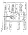
- FIG. 1 is a block diagram showing the basic configuration of a data communication system according to the present invention that is not affected by transmission line characteristics.
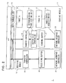
- FIG. 2 is a block diagram showing the general configuration of the data communication terminal 1 in FIG. 1.
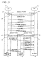
- FIG. 3 is a diagram showing the concept of a connection between the data communication terminal 1 and a linking server 6 and between the linking server 6 and an AP server 9.
- FIG. 4 is a diagram showing an example of the table 14 in FIG. 2.
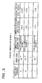
- FIG. 5 is a diagram showing an example of the table 17 in FIG. 2.
- FIG. 6 is a diagram showing an example of operation in which a retransmission timer is set in the data communication system.
- FIG. 7 is a diagram showing an example of operation in which information on the type of the communication network, to which the network interface controller 22 in FIG. 2 is connected, is sent to the transfer controller 19 and the buffer size controller 20 to set the retransmission timer.
- FIG. 8 is a diagram showing the free space of a receiving buffer at a destination.
- FIG. 9 is a diagram showing the relation between an application server processing time and a retransmission time.
- FIG. 1 is a block diagram of a data communication system according to the present invention that is not affected by transmission line characteristics.
- a data communication terminal 1 is provided in the data communication system.
- the data communication terminal 1 sends data to or from an application server (AP server) using the same transmission protocol via one type (or species) of a wire communication network 7, a wireless communication network 4, and both the wireless communication network 4 and the wire communication network 7.
- AP server application server
- data refers to user data.
- An AP server 9 is a terminal that establishes a connection with the data communication terminal 1 and sends back a response (including data and information) in response to a request from the data communication terminal 1.
- the wireless communication network 4 which uses a PHS, PDC, and so on, is a communication network that connects a base station 3 to a linking (or relaying) server 6 or to the AP server 9 via a protocol converter 5.
- the base station 3 located in a cell (i. e., a unit area of wireless communication) 2, connects a physical line to the data communication terminal 1.
- the protocol converter 5 converts data communicated between the wireless communication network 4 and the wire communication network 7 in accordance with the communication network.
- the wire communication network 7, which uses LANs (Local Area Network) or the Internet, is a communication network that connects to the AP server 9 via a network interface unit 8 such as a router.
- LANs Local Area Network
- the wire communication network 7 is a communication network that connects to the AP server 9 via a network interface unit 8 such as a router.
- the linking server 6 is a terminal that subdivides the connection between the data communication terminal 1 and the AP server 9 into two sub-connections: a first sub-connection between the data communication terminal 1 and the linking server 6 and a second sub-connection between the linking server 6 and the AP server 9.
- the linking server 6 applies a transmission protocol to each sub-connection to reduce the amount of packets sent to or received by the wireless communication network 4. It may also act as or substitute for the AP server 9.
- a packet refers to a data block composed of user data and a header or composed of control data and a header.
- FIG. 2 is a block diagram showing a general configuration of the data communication terminal 1 shown in FIG. 1.
- the data communication terminal 1 comprises a sending module 11 and a receiving module 12 which establish a connection with the AP server 9 for sending and receiving packets to or from it, an AP 10, and data transfer unit 13 that is a data transfer path between the sending module 11/receiving module 12 and the AP 10.
- the sending module 11 comprises a table (table A) 14 which contains information on the relation between a pair of a service identifier/destination address and a server processing time required for a service indicated by the service identifier; a retransmission timer setting unit 16 which sets a retransmission timer value (a period of time between the moment a packet is sent and the moment the packet is determined as lost or failed and is retransmitted; a table (table B) 17 which contains information on the correlation between the radio communication network status (radio wave strength between the data communication terminal and the base station, or error rate of data sent or received to or from the wireless communication network) and the sending buffer size; and a radio status acquisition unit 18 which acquires the status of the wireless communication network 4 from the base station 3.
- table (table A) 14 which contains information on the relation between a pair of a service identifier/destination address and a server processing time required for a service indicated by the service identifier
- a retransmission timer setting unit 16 which sets a retrans
- a transfer controller 19 which establishes a connection with the transfer controller of the AP server 9 for transmission of packets; a buffer size controller 20 which adjusts the size of a sending buffer 21 based on the status of the wireless communication network 4 and information in the table 17; a variable-length sending buffer 21 in which data to be sent to the AP server 9 is stored; and a network interface controller 22 which sends packets to the wire communication network 7 or the wireless communication network 4.
- the receiving module 12 comprises a transfer controller 23 which receives packets from the transfer controller of the AP server 9; a receiving buffer 24; and a network interface controller 25 which receives packets from the wire communication network 7 or the wireless communication network 4.
- the sending module 11 and the receiving module 12 are separated to simplify the description. These two modules may be integrated into one.
- FIG. 3 is a diagram showing the concept of a connection between the data communication terminal 1, linking server 6, and AP server 9.
- a transmission protocol for implementing reliable, connection-oriented data reception and transmission such as TCP (Transmission Control Protocol)
- TCP Transmission Control Protocol
- access points 27 and 28 each identified by a pair of a service identifier and a sending address, are provided to the AP 10 and AP 26, respectively.
- a connection 29 is established for each two (pair) applications (server and/or terminal) which communicate each other.
- the AP 10 and the AP 26 send and receive three types of phase data -- a request, a response, and an acknowledgment - - via the connection 29.
- the linking server 6, which acts as an end point of the wireless communication network 4 and the wire communication network 7, divides the connection 29 into two sub-connections: one is a sub-connection 30 between the data communication terminal 1 and the linking server 6, and the other is a sub-connection 31 between the linking server 6 and the AP server 9. This division allows a larger amount of processing for a request to be executed in the wire communication network 7 (between the linking server 6 and the AP server 9), thus reducing the number of packets that are sent to or received by the wireless communication network 4.
- FIG. 4 is a diagram showing an example of the table 14 shown in FIG. 2. As shown in FIG. 4(a), the table 14 is composed of items including service identifier, destination address, communication network type, and server processing time (RTT(s)).
- RTT server processing time
- the service identifier is a value identifying a service to be executed between the data communication terminal 1 and the AP server 9.
- the destination address is a value identifying the physical address (destination) of the AP server 9.
- the communication network type is a value identifying the communication network to which the data communication terminal 1 is to be connected.
- the AP server processing time is a period of time between a moment the data communication terminal 1 starts to send a packet and a moment a response to the packet is received on the connection 29 or the sub-connection 30.
- This connection or a sub-connection is the one established by the data communication terminal 1 and the AP server 9 between the access points 27 and 28, each identified by a pair of the service identifier and the destination address.
- the server processing time is to be defined preliminarily for each service.
- FIG. 5 is a diagram showing an example of the table 17 shown in FIG. 5.
- the table 17 is composed of items including radio wave strength value between the wireless data communication terminal 1 and wireless the base station 3, error rate of data sent to or received from the wireless communication network 4, communication network type, communication network transmission speed, and sending buffer size.
- the buffer size is reduced because the transmission band of the communication network should be narrow (a smaller amount of data can be transferred per second).
- FIG. 6 is a diagram showing an example of operation that is executed to set the retransmission timer in the data communication system.
- the AP 10 connects a physical line to the AP server 9 via a network interface controller 22 and via the wire communication network 7 or the wireless communication network 4.
- the access point 27 is opened by a pair of the service identifier and the destination address to start sending data to the transfer controller 19.
- step S2 when the access point 27 is opened, the transfer controller 19 passes the pair of the service identifier and the destination address to the retransmission timer setting unit 16.
- step S3 when the pair of the service identifier and the destination address is passed, the retransmission timer setting unit 16 references the table 14 (TABLE A) and sets the corresponding AP server processing time (RTT) as a retransmission time.
- step S4 the communication network type is stored in the buffer.
- the communication network type is the wireless communication network 4
- a radio status acquisition request is sent to the radio status acquisition unit 18.
- step S5 the radio status acquisition unit 18 acquires from the base station 3 a radio wave strength value between the data communication terminal 1 and the base station 3 and an error rate (status of wireless communication network 4) of data sent to or received from the wireless communication network 4. These values are acquired at a given time interval or when the values change. The acquired values are stored in the buffer.
- the status of the wireless communication network 4 is acquired from the base station 3, in most cases, via an AT command interface. This description is omitted here because it is outside the range of the present invention.
- step S6 the transfer controller 19 generates a connection connect request packet to connect to the AP server 9 if a connection is not yet established with the AP server 9.
- the packet identification number and the retransmission timer value are stored in the buffer and a notification is sent to the buffer size controller 20.
- step S7 when a packet other than a connection connect request packet is passed from the transfer control ler 19 and when data is to be sent via the wireless communication network 4, the buffer size controller 20 references the table 17 (TABLE B) to get the sending buffer size corresponding to the pair of the status of the wireless communication network 4 and the communication network type.
- step S8 when the sum of the size of the sending buffer 21 at that time and the size of the packet to be sent is smaller than the storage size of the sending buffer 21, the packet is concatenated to the sending buffer 21.
- step S9 when the packet is concatenated to the sending buffer 21, the network interface controller 22 reads the packet and sends data to the AP server 9 over the communication network.
- step S10 information on the identification number and the size of the concatenated packet is sent (notified) to the retransmission timer setting unit 16.
- the timer is set to activate the retransmission timer setting unit 16 after the time calculated by adding the AP server processing time (RTT) to the radio transmission time.
- RTT AP server processing time
- Radio reception time Maximum notified-packet size/Communication network transmission speed.
- the retransmission timer value corresponding to the packet identification number, which is stored in the buffer, is updated by the radio reception time.
- the communication network transmission speed is the speed obtained from the table 17 (TABLE B) corresponding to the pair of the status of the wireless communication network 4 and the communication network type.
- the retransmission timer setting unit 16 calculates the transmission/reception time for each packet size based on the radio communication network status and the sending/receiving packet size and sets the sum of the AP server processing time and the transmission/reception time of each packet as the retransmission timer value.
- This method allows the retransmission timer value to be set according to the transmission line characteristics.
- FIG. 7 is a diagram showing an example of operation in which the information on the type of the communication network, to which the network interface controller 22 in FIG. 2 is connected, is sent to the transfer controller 19 and the buffer size controller 20 to set the retransmission timer.
- the AP 10 connects a physical line to the AP server 9 via the network interface controller 22 and via the wire communication network 7 or the wireless communication network 4.
- step S22 when the physical line is connected, the network interface controller 22 passes information on the communication type to the transfer controller 19 and the buffer size controller 20.
- step S23 the access point 27 is opened by a pair of the service identifier and the destination address to start sending data to the transfer controller 19.
- step S24 when the access point 27 is opened and when data is to be sent via the wireless communication network 4, the transfer controller 19 passes the pair of the service identifier and the destination address to the retransmission timer setting unit 16.
- step S25 when a connection is not yet established with the AP server 9, a connection connect request packet is generated to request a connection with the AP server.
- the packet identification number and the retransmission timer value are stored in the buffer and a notification is sent to the buffer size controller 20.
- the time between a moment the buffer size controller 20 stores the packet in the sending buffer 21 and a moment the AP server 9 returns a response is measured.
- the retransmission timer value is usually set based on the measured time. The description of how to set the retransmission timer value is omitted here.
- the entry item "communication network type" in the table 14 in FIG. 4 and in the table 17 in FIG. 5 is replaced by the type of the wireless communication network 4 to generate a table (TABLE A') 44 and a table (TABLE B') 45.
- the table 44 and the table 45 are referenced only when data is sent via the wireless communication network 4.
- the system and the method according to the present invention sets the transmission timer properly and therefore reduces the possibility of unnecessary retransmission of packets due to an incorrect data-loss detection or the possibility of unnecessary suppression of transmission at retransmission time, significantly increasing throughput.
- a data communication system which sends or receives data to or from an application server using the same protocol via a transmission line as one of a wire communication network, a wireless communication network, and both a wire communication network and a wireless communication network, comprises a table containing therein a relation among a service identifier of the application server, a destination address, a communication network type, and a processing time of the application server; and a retransmission timer setting unit which references the table to obtain the processing time of the application server based on the service identifier, destination address, and communication network type during transmission or reception of data to or from the application server, and sets the time as a retransmission time.
Landscapes
- Engineering & Computer Science (AREA)
- Computer Networks & Wireless Communication (AREA)
- Signal Processing (AREA)
- Databases & Information Systems (AREA)
- Mobile Radio Communication Systems (AREA)
- Communication Control (AREA)
- Data Exchanges In Wide-Area Networks (AREA)
- Computer And Data Communications (AREA)
- Small-Scale Networks (AREA)
Applications Claiming Priority (2)
| Application Number | Priority Date | Filing Date | Title |
|---|---|---|---|
| JP34406399 | 1999-12-03 | ||
| JP34406399A JP3430509B2 (ja) | 1999-12-03 | 1999-12-03 | データ通信システム及び方法 |
Publications (3)
| Publication Number | Publication Date |
|---|---|
| EP1107540A2 true EP1107540A2 (de) | 2001-06-13 |
| EP1107540A3 EP1107540A3 (de) | 2002-12-11 |
| EP1107540B1 EP1107540B1 (de) | 2005-03-02 |
Family
ID=18366376
Family Applications (1)
| Application Number | Title | Priority Date | Filing Date |
|---|---|---|---|
| EP20000310698 Expired - Lifetime EP1107540B1 (de) | 1999-12-03 | 2000-12-01 | Datenkommunikationsystem und Verfahren |
Country Status (5)
| Country | Link |
|---|---|
| US (1) | US6831908B2 (de) |
| EP (1) | EP1107540B1 (de) |
| JP (1) | JP3430509B2 (de) |
| AU (1) | AU7196600A (de) |
| CA (1) | CA2327309C (de) |
Cited By (4)
| Publication number | Priority date | Publication date | Assignee | Title |
|---|---|---|---|---|
| EP1441485A3 (de) * | 2003-01-24 | 2004-08-04 | Matsushita Electric Industrial Co., Ltd. | Verfahren zum gemeinsamen Schlüsselsaustausch und Kommunikationsgerät |
| WO2004043016A3 (en) * | 2002-11-07 | 2004-10-21 | Koninkl Philips Electronics Nv | System and method for an ieee 802.11 access point to prevent traffic suffering bad link quality from affecting other traffic |
| GB2417392A (en) * | 2004-08-18 | 2006-02-22 | Wecomm Ltd | Determining packet resend latency |
| WO2006089385A1 (en) * | 2005-02-22 | 2006-08-31 | Nextair Corporation | Wireless communication device use of application server applications |
Families Citing this family (23)
| Publication number | Priority date | Publication date | Assignee | Title |
|---|---|---|---|---|
| US20030145089A1 (en) * | 2002-01-29 | 2003-07-31 | Xerox Corporation | System and method for enabling arbitrary components to transfer data between each other |
| US7367029B2 (en) * | 2002-08-01 | 2008-04-29 | Xerox Corporation | Method and system for handling data |
| EP1536597B1 (de) * | 2002-09-06 | 2015-01-21 | Fujitsu Limited | Funknetzwerk-steuervorrichtung |
| US20040109433A1 (en) * | 2002-12-06 | 2004-06-10 | Khan Farooq Ullah | Reverse link packet acknowledgement method |
| JP4214793B2 (ja) | 2003-02-19 | 2009-01-28 | 日本電気株式会社 | 無線通信システム、サーバ、基地局、移動端末及びそれらに用いる再送タイムアウト時間決定方法 |
| US20050041673A1 (en) * | 2003-08-20 | 2005-02-24 | Frances Jiang | Method of managing wireless network resources to gateway devices |
| US7839844B2 (en) * | 2004-07-30 | 2010-11-23 | Sony Corporation | System and method for dynamically determining retransmit buffer time |
| US7643503B2 (en) | 2004-07-30 | 2010-01-05 | Sony Corporation | System and method for dynamically determining retransmit buffer time |
| JP2007259274A (ja) | 2006-03-24 | 2007-10-04 | Sony Corp | 再送制御回路、送信装置、再送制御方法及び再送制御プログラム |
| US9614648B2 (en) * | 2006-04-29 | 2017-04-04 | Philips Lighting Holding B.V. | Method and apparatus for controlling energy expanding of sensor network nodes |
| US8230288B2 (en) * | 2006-10-18 | 2012-07-24 | Samsung Electronics Co., Ltd. | Data transmission apparatus and method for applying an appropriate coding rate |
| US8199758B2 (en) * | 2008-02-13 | 2012-06-12 | Qualcomm Incorporated | Variable abort timer |
| KR101447209B1 (ko) * | 2008-07-03 | 2014-10-06 | 에스케이텔레콤 주식회사 | 이동통신 시스템에서 무선 링크 프로토콜 제어 장치 및방법 |
| US8554956B1 (en) | 2010-02-24 | 2013-10-08 | Open Invention Network Llc | Method for creation of a device driver for a peripheral device |
| US8935434B1 (en) * | 2010-02-24 | 2015-01-13 | Open Invention Network, Llc | Interconnection of peripheral devices on different electronic devices |
| US8554957B1 (en) | 2010-02-24 | 2013-10-08 | Open Invention Network, Llc | Method for creation of device drivers and device objects for peripheral devices |
| JP5760325B2 (ja) * | 2010-03-29 | 2015-08-05 | 富士通株式会社 | 通信装置および通信方法 |
| JP5956729B2 (ja) | 2011-07-22 | 2016-07-27 | キヤノン株式会社 | リレーサーバ、リレーサーバの制御方法、情報処理システム、およびプログラム |
| KR101819029B1 (ko) * | 2011-09-29 | 2018-01-16 | 삼성전자주식회사 | 서비스 제공 방법 및 그 장치 |
| FR2995168B1 (fr) * | 2012-08-30 | 2014-08-29 | Commissariat Energie Atomique | Procede de gestion d'un point d'acces d'un reseau de communication en fonction du trafic |
| KR102037413B1 (ko) * | 2013-02-22 | 2019-11-26 | 삼성전자주식회사 | 스트리밍 서비스를 제공하기 위한 동적 버퍼링 방법 및 그 장치 |
| JP6554011B2 (ja) * | 2015-10-07 | 2019-07-31 | 日本電信電話株式会社 | タイムアウト時間設定装置とタイムアウト時間設定方法 |
| US11758434B2 (en) * | 2020-10-20 | 2023-09-12 | Harman International Industries, Incorporated | Dynamic buffer allocation for bluetooth low energy isochronous transmissions |
Family Cites Families (10)
| Publication number | Priority date | Publication date | Assignee | Title |
|---|---|---|---|---|
| JPS63299631A (ja) | 1987-05-29 | 1988-12-07 | Nec Corp | デ−タパケット再送タイミング決定方式 |
| US5774479A (en) * | 1995-03-30 | 1998-06-30 | Motorola, Inc. | Method and system for remote procedure call via an unreliable communication channel using multiple retransmission timers |
| US5862326A (en) * | 1995-09-21 | 1999-01-19 | Pacific Communication Sciences, Inc. | Efficient request-reply protocol for a client-server model |
| US6137802A (en) * | 1997-03-25 | 2000-10-24 | Motorola, Inc. | Automatic media switching apparatus and method |
| US6088588A (en) * | 1997-03-25 | 2000-07-11 | Nortel Networks Corporation | Method and wireless terminal for monitoring communications and providing network with terminal operation information |
| US6557134B2 (en) * | 1997-09-30 | 2003-04-29 | Glenayre Electronics, Inc. | ARQ method for wireless communication |
| US6226301B1 (en) * | 1998-02-19 | 2001-05-01 | Nokia Mobile Phones Ltd | Method and apparatus for segmentation and assembly of data frames for retransmission in a telecommunications system |
| US6076181A (en) * | 1998-03-03 | 2000-06-13 | Nokia Mobile Phones Limited | Method and apparatus for controlling a retransmission/abort timer in a telecommunications system |
| JPH11266276A (ja) | 1998-03-18 | 1999-09-28 | Hitachi Ltd | コマンド/データ再生方法 |
| US6473399B1 (en) * | 1998-11-30 | 2002-10-29 | Telefonaktiebolaget Lm Ericsson (Publ) | Method and apparatus for determining an optimum timeout under varying data rates in an RLC wireless system which uses a PDU counter |
-
1999
- 1999-12-03 JP JP34406399A patent/JP3430509B2/ja not_active Expired - Fee Related
-
2000
- 2000-11-30 CA CA 2327309 patent/CA2327309C/en not_active Expired - Fee Related
- 2000-12-01 EP EP20000310698 patent/EP1107540B1/de not_active Expired - Lifetime
- 2000-12-01 AU AU71966/00A patent/AU7196600A/en not_active Abandoned
- 2000-12-04 US US09/729,045 patent/US6831908B2/en not_active Expired - Fee Related
Cited By (8)
| Publication number | Priority date | Publication date | Assignee | Title |
|---|---|---|---|---|
| WO2004043016A3 (en) * | 2002-11-07 | 2004-10-21 | Koninkl Philips Electronics Nv | System and method for an ieee 802.11 access point to prevent traffic suffering bad link quality from affecting other traffic |
| EP1441485A3 (de) * | 2003-01-24 | 2004-08-04 | Matsushita Electric Industrial Co., Ltd. | Verfahren zum gemeinsamen Schlüsselsaustausch und Kommunikationsgerät |
| GB2417392A (en) * | 2004-08-18 | 2006-02-22 | Wecomm Ltd | Determining packet resend latency |
| GB2417392B (en) * | 2004-08-18 | 2007-05-09 | Wecomm Ltd | Transmitting packets of data |
| US7551649B2 (en) | 2004-08-18 | 2009-06-23 | Wecomm Limited | Transmitting packets of data |
| WO2006089385A1 (en) * | 2005-02-22 | 2006-08-31 | Nextair Corporation | Wireless communication device use of application server applications |
| US7668937B2 (en) | 2005-02-22 | 2010-02-23 | Research In Motion Limited | Wireless communication device use of application server applications |
| US8190712B2 (en) | 2005-02-22 | 2012-05-29 | Research In Motion Limited | Wireless communication device use of application server applications |
Also Published As
| Publication number | Publication date |
|---|---|
| JP2001160842A (ja) | 2001-06-12 |
| EP1107540B1 (de) | 2005-03-02 |
| US6831908B2 (en) | 2004-12-14 |
| AU7196600A (en) | 2001-06-07 |
| US20010002910A1 (en) | 2001-06-07 |
| JP3430509B2 (ja) | 2003-07-28 |
| CA2327309C (en) | 2004-11-02 |
| EP1107540A3 (de) | 2002-12-11 |
| CA2327309A1 (en) | 2001-06-03 |
Similar Documents
| Publication | Publication Date | Title |
|---|---|---|
| US6831908B2 (en) | Data communication system and method | |
| US7369498B1 (en) | Congestion control method for a packet-switched network | |
| US6643259B1 (en) | Method for optimizing data transfer in a data network | |
| US6584083B1 (en) | Internet over satellite method | |
| US6529477B1 (en) | Internet over satellite system | |
| US6654344B1 (en) | Method and system for controlling data flow in an internet over satellite connection | |
| US8843654B2 (en) | Data packet transfer over wide area network in fast and reliable manner | |
| US6460085B1 (en) | Method and system for managing memory in an internet over satellite connection | |
| US6934255B1 (en) | Internet over satellite apparatus | |
| EP3522479A1 (de) | Techniken zur effizienten mehrwegeübertragung | |
| US20050195821A1 (en) | Method and apparatus for dynamically controlling traffic in wireless station | |
| WO2000046669A9 (en) | Internet over satellite | |
| JP2001518725A (ja) | 無線マルチサービス通信環境内の再送信パケット取得システム | |
| JP2008508817A (ja) | 低頻度ackのシステムに適した高性能tcp | |
| US11165893B2 (en) | Techniques for packet data conversion | |
| EP1177668A2 (de) | Headerkomprimierung | |
| CN113424578B (zh) | 一种传输控制协议加速方法和装置 | |
| JP3434231B2 (ja) | Tcp制御方法 | |
| EP1505759B1 (de) | Verfahren und Gerät zum Übertragen/Empfangen von Daten mittels bestätigter Transportschichtprotokolle | |
| US20060209687A1 (en) | Communication rate control method and device | |
| WO2002025880A2 (en) | Dynamic tcp configuration for low latency voice/data traffic | |
| JP2984910B2 (ja) | データフロー制御方法 | |
| JP2004208119A (ja) | フレームリレーネットワークにおけるパケット送受信装置 | |
| Brown et al. | An analysis of HF for IP sub-networks | |
| Kliazovich et al. | Cross-layer congestion control in multi-hop wireless local area networks |
Legal Events
| Date | Code | Title | Description |
|---|---|---|---|
| PUAI | Public reference made under article 153(3) epc to a published international application that has entered the european phase |
Free format text: ORIGINAL CODE: 0009012 |
|
| AK | Designated contracting states |
Kind code of ref document: A2 Designated state(s): AT BE CH CY DE DK ES FI FR GB GR IE IT LI LU MC NL PT SE TR |
|
| AX | Request for extension of the european patent |
Free format text: AL;LT;LV;MK;RO;SI |
|
| PUAL | Search report despatched |
Free format text: ORIGINAL CODE: 0009013 |
|
| AK | Designated contracting states |
Kind code of ref document: A3 Designated state(s): AT BE CH CY DE DK ES FI FR GB GR IE IT LI LU MC NL PT SE TR |
|
| AX | Request for extension of the european patent |
Free format text: AL;LT;LV;MK;RO;SI |
|
| 17P | Request for examination filed |
Effective date: 20021129 |
|
| 17Q | First examination report despatched |
Effective date: 20030711 |
|
| AKX | Designation fees paid |
Designated state(s): FI GB SE |
|
| REG | Reference to a national code |
Ref country code: DE Ref legal event code: 8566 |
|
| GRAP | Despatch of communication of intention to grant a patent |
Free format text: ORIGINAL CODE: EPIDOSNIGR1 |
|
| GRAS | Grant fee paid |
Free format text: ORIGINAL CODE: EPIDOSNIGR3 |
|
| GRAA | (expected) grant |
Free format text: ORIGINAL CODE: 0009210 |
|
| AK | Designated contracting states |
Kind code of ref document: B1 Designated state(s): FI GB SE |
|
| REG | Reference to a national code |
Ref country code: GB Ref legal event code: FG4D |
|
| REG | Reference to a national code |
Ref country code: IE Ref legal event code: FG4D |
|
| REG | Reference to a national code |
Ref country code: SE Ref legal event code: TRGR |
|
| PLBE | No opposition filed within time limit |
Free format text: ORIGINAL CODE: 0009261 |
|
| STAA | Information on the status of an ep patent application or granted ep patent |
Free format text: STATUS: NO OPPOSITION FILED WITHIN TIME LIMIT |
|
| 26N | No opposition filed |
Effective date: 20051205 |
|
| PGFP | Annual fee paid to national office [announced via postgrant information from national office to epo] |
Ref country code: FI Payment date: 20081212 Year of fee payment: 9 |
|
| PGFP | Annual fee paid to national office [announced via postgrant information from national office to epo] |
Ref country code: SE Payment date: 20081205 Year of fee payment: 9 |
|
| PGFP | Annual fee paid to national office [announced via postgrant information from national office to epo] |
Ref country code: GB Payment date: 20081126 Year of fee payment: 9 |
|
| EUG | Se: european patent has lapsed | ||
| GBPC | Gb: european patent ceased through non-payment of renewal fee |
Effective date: 20091201 |
|
| PG25 | Lapsed in a contracting state [announced via postgrant information from national office to epo] |
Ref country code: FI Free format text: LAPSE BECAUSE OF NON-PAYMENT OF DUE FEES Effective date: 20091201 |
|
| PG25 | Lapsed in a contracting state [announced via postgrant information from national office to epo] |
Ref country code: GB Free format text: LAPSE BECAUSE OF NON-PAYMENT OF DUE FEES Effective date: 20091201 |
|
| PG25 | Lapsed in a contracting state [announced via postgrant information from national office to epo] |
Ref country code: SE Free format text: LAPSE BECAUSE OF NON-PAYMENT OF DUE FEES Effective date: 20091202 |