EP1107409A1 - Interrupteur et son procédé de fabrication - Google Patents
Interrupteur et son procédé de fabrication Download PDFInfo
- Publication number
- EP1107409A1 EP1107409A1 EP00126303A EP00126303A EP1107409A1 EP 1107409 A1 EP1107409 A1 EP 1107409A1 EP 00126303 A EP00126303 A EP 00126303A EP 00126303 A EP00126303 A EP 00126303A EP 1107409 A1 EP1107409 A1 EP 1107409A1
- Authority
- EP
- European Patent Office
- Prior art keywords
- switchgear
- resin
- molded
- bloc
- metal
- Prior art date
- Legal status (The legal status is an assumption and is not a legal conclusion. Google has not performed a legal analysis and makes no representation as to the accuracy of the status listed.)
- Granted
Links
Images


Classifications
-
- H—ELECTRICITY
- H02—GENERATION; CONVERSION OR DISTRIBUTION OF ELECTRIC POWER
- H02B—BOARDS, SUBSTATIONS OR SWITCHING ARRANGEMENTS FOR THE SUPPLY OR DISTRIBUTION OF ELECTRIC POWER
- H02B1/00—Frameworks, boards, panels, desks, casings; Details of substations or switching arrangements
- H02B1/56—Cooling; Ventilation
-
- H—ELECTRICITY
- H02—GENERATION; CONVERSION OR DISTRIBUTION OF ELECTRIC POWER
- H02B—BOARDS, SUBSTATIONS OR SWITCHING ARRANGEMENTS FOR THE SUPPLY OR DISTRIBUTION OF ELECTRIC POWER
- H02B13/00—Arrangement of switchgear in which switches are enclosed in, or structurally associated with, a casing, e.g. cubicle
- H02B13/01—Arrangement of switchgear in which switches are enclosed in, or structurally associated with, a casing, e.g. cubicle with resin casing
-
- H—ELECTRICITY
- H02—GENERATION; CONVERSION OR DISTRIBUTION OF ELECTRIC POWER
- H02B—BOARDS, SUBSTATIONS OR SWITCHING ARRANGEMENTS FOR THE SUPPLY OR DISTRIBUTION OF ELECTRIC POWER
- H02B13/00—Arrangement of switchgear in which switches are enclosed in, or structurally associated with, a casing, e.g. cubicle
- H02B13/02—Arrangement of switchgear in which switches are enclosed in, or structurally associated with, a casing, e.g. cubicle with metal casing
- H02B13/035—Gas-insulated switchgear
- H02B13/0354—Gas-insulated switchgear comprising a vacuum switch
-
- H—ELECTRICITY
- H01—ELECTRIC ELEMENTS
- H01H—ELECTRIC SWITCHES; RELAYS; SELECTORS; EMERGENCY PROTECTIVE DEVICES
- H01H11/00—Apparatus or processes specially adapted for the manufacture of electric switches
- H01H11/0006—Apparatus or processes specially adapted for the manufacture of electric switches for converting electric switches
- H01H11/0031—Apparatus or processes specially adapted for the manufacture of electric switches for converting electric switches for allowing different types or orientation of connections to contacts
-
- H—ELECTRICITY
- H01—ELECTRIC ELEMENTS
- H01H—ELECTRIC SWITCHES; RELAYS; SELECTORS; EMERGENCY PROTECTIVE DEVICES
- H01H9/00—Details of switching devices, not covered by groups H01H1/00 - H01H7/00
- H01H9/52—Cooling of switch parts
- H01H2009/523—Cooling of switch parts by using heat pipes
-
- H—ELECTRICITY
- H01—ELECTRIC ELEMENTS
- H01H—ELECTRIC SWITCHES; RELAYS; SELECTORS; EMERGENCY PROTECTIVE DEVICES
- H01H33/00—High-tension or heavy-current switches with arc-extinguishing or arc-preventing means
- H01H33/02—Details
- H01H33/53—Cases; Reservoirs, tanks, piping or valves, for arc-extinguishing fluid; Accessories therefor, e.g. safety arrangements, pressure relief devices
- H01H33/56—Gas reservoirs
- H01H2033/566—Avoiding the use of SF6
-
- H—ELECTRICITY
- H01—ELECTRIC ELEMENTS
- H01H—ELECTRIC SWITCHES; RELAYS; SELECTORS; EMERGENCY PROTECTIVE DEVICES
- H01H33/00—High-tension or heavy-current switches with arc-extinguishing or arc-preventing means
- H01H33/60—Switches wherein the means for extinguishing or preventing the arc do not include separate means for obtaining or increasing flow of arc-extinguishing fluid
- H01H33/66—Vacuum switches
- H01H33/6606—Terminal arrangements
- H01H2033/6613—Cooling arrangements directly associated with the terminal arrangements
-
- H—ELECTRICITY
- H01—ELECTRIC ELEMENTS
- H01H—ELECTRIC SWITCHES; RELAYS; SELECTORS; EMERGENCY PROTECTIVE DEVICES
- H01H33/00—High-tension or heavy-current switches with arc-extinguishing or arc-preventing means
- H01H33/60—Switches wherein the means for extinguishing or preventing the arc do not include separate means for obtaining or increasing flow of arc-extinguishing fluid
- H01H33/66—Vacuum switches
- H01H33/662—Housings or protective screens
- H01H33/66207—Specific housing details, e.g. sealing, soldering or brazing
- H01H2033/6623—Details relating to the encasing or the outside layers of the vacuum switch housings
-
- H—ELECTRICITY
- H01—ELECTRIC ELEMENTS
- H01H—ELECTRIC SWITCHES; RELAYS; SELECTORS; EMERGENCY PROTECTIVE DEVICES
- H01H31/00—Air-break switches for high tension without arc-extinguishing or arc-preventing means
- H01H31/003—Earthing switches
-
- H—ELECTRICITY
- H01—ELECTRIC ELEMENTS
- H01H—ELECTRIC SWITCHES; RELAYS; SELECTORS; EMERGENCY PROTECTIVE DEVICES
- H01H33/00—High-tension or heavy-current switches with arc-extinguishing or arc-preventing means
- H01H33/02—Details
- H01H33/027—Integrated apparatus for measuring current or voltage
-
- H—ELECTRICITY
- H01—ELECTRIC ELEMENTS
- H01H—ELECTRIC SWITCHES; RELAYS; SELECTORS; EMERGENCY PROTECTIVE DEVICES
- H01H33/00—High-tension or heavy-current switches with arc-extinguishing or arc-preventing means
- H01H33/60—Switches wherein the means for extinguishing or preventing the arc do not include separate means for obtaining or increasing flow of arc-extinguishing fluid
- H01H33/66—Vacuum switches
Definitions
- the present invention relates to a switchgear, and more particularly to a switchgear comprising a vacuum circuit breaker, vacuum disconnector or similar vacuum switch used for interruption and continuity or switching in electric power and reception and/or distribution systems.
- Fig. 1 illustrates an example of the configuration of a typical switchgear as used in electric power and reception and/or distribution systems.
- a receptacle 101 is surrounded with mild steel plating and divided internally with a partition 103.
- a circuit breaker chamber 105 at the front houses a circuit breaker 109 fitted with a vacuum valve 107, while a bus-line chamber 111 at the rear is equipped with identical disconnectors 113 and 114 corresponding to upper and lower main circuits on the circuit breaker 109 side.
- the upper disconnector 113 side is connected to a bus-line 117 which is fixed to a supporting insulator 115, and is thence connected to a neighbouring board.
- the lower disconnector 114 side is connected to a cable head 121 which is fed by an electric power cable 119. These pieces of apparatus are mutually connected by means of a connecting conductor 123.
- a connecting conductor 123 In the partition 103 which separates the source side from the load side is an aperture not illustrated in the drawing is an insulating spacer 125 formed by molding the principal circuit conductor in an insulating layer, and the principal circuit is connected to the mutual partition of the chambers 105 and 111.
- These chambers 105 and 111 are charged with an insulating medium such as SF6 gas.
- SF6 gas is characterized among other qualities by being colorless, harmless and inert. At atmospheric pressure it has 2-3 times the dielectric strength of air. A gear switch charged with a gas of this sort ensures a stable supply of electric power.
- SF6 gas has a higher degree of dielctric strength than air, and consequently allows the switchgear to be made more compact as described for instance in Japanese Laid-Open Patent Application S60[1985]-210107.
- S60[1985]-210107 Japanese Laid-Open Patent Application S60[1985]-210107.
- one object of the present invention which has been designed in response to the above mentioned problems, is to provide a novel switchgear and method of manufacturing the same which is both economical and efficient by virtue of the fact that the whole device is molded en bloc at high speed, thus reducing both the number of parts and the number of man hours required for molding,
- this is achieved thanks to the solid insulation of vacuum valves having among other functions those of vacuum circuit breaker and vacuum disconnector, thus providing a degree of dielectric strength which surpasses that of SF6 gas insulation, while at the same time rendering the whole device more compact.
- the present invention is a switchgear having a switching apparatus with a vacuum circuit breaker, vacuum disconnector or similar vacuum valve, an input member of the switching apparatus whereby electric power is input from the exterior, and an output member of the switching apparatus whereby electric power is output to the exterior, the whole switching apparatus being molded en bloc in a resin layer together with the input member and the output member.
- vacuum valves sometimes mean vacuum interrupter or vacuum disconnector. If the valves are assembled as they are, the distance between them has to be increased in accordance with the dielectric strength of air. Molding two vacuum valves with differing functions en bloc allows the insulation between the valves to be determined by the dielectric strength of the resin used in the molding. The dielectric strength of the molded resin is approximately one digit higher than that of air or SF6 gas. This means that the insulation distance of the vacuum valves which correspond to the nerve center of the switchgear can be greatly reduced, allowing the whole device to be rendered more compact.
- the outer surface of the molded resin layer forms an earth layer.
- the area between the conductor and the vacuum valves within the molded resin becomes a solid resin insulator, permitting of greater compactness in comparison with air and other gaseous insulators.
- the three are separated when an earth layer is formed on the outer surface of each phase, eliminating inter-phase shorting and doing away with the need for any distance between the phases. This also allows the device to be made more compact, as does the fact that it is no longer necessary to pay any attention to soiling or damage when designing the device as they do not affect its insulation properties. What is more, it also does away with the need for maintenance against soiling and damage.
- the input and output members form a T-junction.
- T-junction in this manner ensures ample variation in the input and output members, enabling the fitting of current transformers and arresters without modifying the mold.
- the mold used in molding the switchgear is such that at least the input and output members are interchangeable, and the gear switch can be molded en bloc in accordance with the structure and shape of the input and output members.
- the device becomes more cost-effective because there is no longer any need to mold the current and voltage sensors separately.
- the main body of the switchgear and the insulating medium form a single solid insulator, the dielectric strength increases and it is possible to reduce the dimensions of the switchgear including the voltage and current sensors.
- the spacer in order to maintain insulation distance, or to increase the rigidity of the conductor and allow it to float in space within the mold, by allocating this function to voltage and current sensors it is possible to do away with the spacer and there is no need for the conductor to be particularly rigid, making it easier and more economical to manufacture.
- a more economical switchgear can be provided if a molded potential transformer(PT or VT(voltage transformer)) or arrester is fitted to one side of the T-junction.
- electrically conductive metal caps are fitted to both end surfaces of the vacuum valve in such a manner as to cover the end surfaces of the insulation tube thereof, these being included with the other parts and molded en bloc.
- both ends of the vacuum valve are made of metal, stress is easily generated when it is molded in resin on account of the contact between different materials. This stress increases with length, but if a metal cap is fitted there is no risk of insulation breakdown even if peeling or cracking occurs between this metal cap and the end of the valve because in electrical terms the cap and the end of the valve have the same potential.
- an elastomer is introduced into the area between both the end surfaces of the vacuum valve and the electrically conductive metal caps fitted thereto, while a high-strength fiber material is wrapped round between the end surfaces of the electrically conductive metal caps and the insulation tube of the vacuum valve so as to cover the end surfaces of the insulation tube, these being included with the other parts and molded en bloc.
- the bulking agent (or filler) for the molded resin comprises a fused silica bulking agent and fine elastomer particles, the latter being dispersed in a proportion of approximately 5-20% to the resin.
- the switcn gear is molded en bloc by means of high-speed molding wherein an accelerator is added to the resin in order to promote a reaction on the upside of 100°C, the interior of the mold is depressurized, the resin poured in and the mold released after 20-30 minutes.
- the molded resin is pressurized and cured successively from the section farthest from the sprue, resin being added continuously so as to provide a product without sink mark in a short time.
- Depressurising the interior of the metal mold while molding en bloc allows air to be expelled from inside, thus minimizing the occurrence of voids, while the difference in pressure while the resin is being poured facilitates pouring from the bottom.
- the resin absorbs heat from the metal mold and increases in temperature, so that the resin which was poured first is cured more rapidly than the resin nearer the sprue, and gelates quickly. As it hardens, the resin contracts and sink marks appear unless more resin is added. The fact that the resin nearer the sprue is slow to harden allows more resin to be added, thus making it possible to provide a product without sink marks.
- the switchgear is molded en bloc by high-speed molding using a metal mold with a plurality of resin inlets, resin pools and deaeration members.
- an electrically conductive coating is sprayed on to the face of the metal mold corresponding to the outer surface of the switchgear, whereupon the component parts of the switchgear are set in the metal mold and molded en bloc in such a manner that the electrically conductive coating is transferred to the outer surface of the resin. forming a single entity with the molded resin layer.
- Spraying the part of the metal mold which corresponds to the surface of the molded product in advance with an electrically conductive coating allows the resin and electrically conductive coating to adhere within the mold when subsequently the metal mold is closed and the resin poured in, so that when the mold is released, the surface of the molded resin and the coating form a single entity. This is economical because it eliminates the process of forming the electrically conductive layer after molding is complete.
- the mold when the switchgear is molded en bloc in resin and the resin has gelated, the mold is released sufficiently for the electrically conductive coating to fluidize, after which the coating is forced into the space between the molded product and the metal mold, whereupon the mold is closed to the thickness of an electrically conductive layer and heat-cured in order to form the electrically conductive layer on the outer surface of the molded product.
- the mold when the switchgear is being molded en bloc in resin, the mold is released when the molded resin has gelated, and the surface of the molded product is covered with an electrically preimpregnated conductive sheet (that is to say, prepreg conductive sheet), after which the metal mold is clamped, and the electrically prepreg conductive sheet heated and pressurized, thus ensuring that it forms a single entity with the molded product, on the surface of which an electrically conductive layer is created
- an electrically preimpregnated conductive sheet that is to say, prepreg conductive sheet
- the metal mold is released and the surface of the molded product is covered with a pre-impregnated electrically conductive sheet, after which the mold is clamped, heat and pressure being applied to the sheet in order for it to form an entity with the molded product.
- the pre-impregnated electrically conductive sheet (that is to say, prepreg conductive sheet) acts as a protective layer for the molded surface, at the same time enabling it to be formed to a prescribed thickness.
- the fact that the thickness is uniform means that the rate of conduction is stable, and the use of high-strength fibers in the pre-impregnated material also serves to prevent breakage.
- the movable sides of the vacuum valves are arranged in the same direction, the connecting members including sliding members on the movable side comprising a single conductor, which is molded en bloc with the vacuum valves.
- the connecting members including sliding members and the movable side of the vacuum valves are assembled and set in the metal mold prior to molding, the positional relationship is determined in the metal mold, thus eliminating the troublesome task of adjusting the dimensions.
- the movable sides of the two vacuum valves are arranged in the same direction, the ends of the movable sides are easily supported by the metal members, and it is easy to mitigate the electric fields at the ends.
- the connecting members are molded and insulated at the same time, it is possible to reduce the exposed sections of the movable sides, and consequently also the task of insulation in subsequent processing.
- the outer surface of the molded switchgear assumes the shape of a fin for the purpose of cooling.
- the fact that a fin is attached to the surface of the molded product means that the surface area which comes into contact with the air is increased, improving the cooling performance and allowing the switchgear to be made more compact.
- a metal fin is placed on the outer surface during the molding of the switchgear, which is then molded en bloc along with the metal fin.
- the metal fin exhibits superior heat conductivity to organic materials such as molded resin, with resultant improved cooling efficiency. Moreover, because the fin is made of metal, it will now break if knocked, permitting greater stability of quality during movement and transportation.
- metal is embedded in the outer surface during the molding of the switchgear, and a heat pipe with a fin is attached thereto.
- the presence of the heat pipe with attached cooling fin makes it easier to cool the interior of the molded product, thus increasing the capacity of the switchgear.
- the switchgear is assembled in a three-phase shape with the aid of the heat pipe with fin, and fixed to the face of a board on both sides also with the aid of the heat pipe.
- Using the heat pipe with attached fin when assembling the switchgear into three-phase shape not only serves to improve cooling within the board, but also the fact that the board itself acts as a heat release surface, allows the cooling area to be increased, improving efficiency of cooling and allowing the switchgear to be made more compact.
- a sealed heat pipe connected to a vacuum valve is employed within the switchgear.
- Fig. 2 is a cross-sectional drawing of the principal section of a switchgear illustrating the first embodiment of the present invention
- Fig. 3 is a one-line diagram of a switchgear.
- Fig. 2 shows a cross-section of one phase of a switchgear 1.
- a fixed conductor forming an electrode divides into a T-ahape junction and connects to a vacuum disconnector 7 having an earth function.
- a movable-side conductor 9 which forms the electrode of the vacuum valve which constitutes the vacuum disconnector 7 connects by way of a multi-contact band or other connecting member 11 to a movable-side conductor 15 which forms the electrode of a vacuum valve 13 which constitutes a vacuum circuit breaker.
- a fixed conductor 17 of the vacuum valve 13 connects by way of a conductor 19 to a T-junction cable head receptor 21.
- a single molded product is obtained by introducing the above into a mold not illustrated in the drawing, pouring resin 23 into the metal mold and heat-curing it.
- the bus-line connecting member 3 and the cable head receptor 21, which form the input and output respectively are such that they are capable of being molded in interchangeable metal molds.
- an electrically conductive layer is provided on the outer surface of the molded resin except for the inner face on the movable side of the vacuum valves 7, 13 and the section where the busline connecting member 3 and the cable head receptor 21 engage.
- VT molded voltage transformer
- PT potential transformer
- VD voltage device
- PD potential device
- the movable conductor 15 is supported on a metal endplate 41 in such a manner as to be capable of moving up and down with the aid of expandable bellows 39.
- the upper and lower metal endplates 39 and 41 are welded to the insulation tube 35 in a state of vacuum, which is preserved within the circuit breaker.
- Fig. 5 is an outline cross-sectional drawing of vacuum valve 7 for the vacuum disconnector with bullt-in earth function employed in the present invention.
- a molded product wherein T-junction input and output members 3 and 21 respectively connected to two vacuum valves 7 and 13 with differing functions are molded en bloc is fitted with movable side conductors 9 and 15, a connecting member 11 and an operational rod 31 and assembled on an operational mechanism not illustrated in the drawings to form a switchgear.
- a voltage transformer (VT) 25 molded en bloc is attached to the upper side of the cable head receptor 21.
- a current transformer (CT) 29 also molded en bloc is attached to allow the cable 27 through. It should be added that if there is no need to attach a molded voltage transformer (VT) 25, it is possible to attach an insulation plug, which can be used to connect an external power supply when testing the cables, or to fit an arrester to this section.
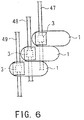
- a three-phase switchgear can be configured by staggering molded one-phase switch-gears 1 left and right as illustrated so that the bus-lines 47, 48 and 49 do not overlap one another.
- a switchgear 1 configured in this manner requires circuit breaking, disconnecting and earthing functions, and because switching is performed within a vacuum with excellent characteristics, these various functions can be implemented with the aid of the small vacuum valves 7 and 13.
- These vacuum valves 7 and 13 need to be insulated on account of the high surge voltage which is generated between the electrodes and in the earth on connection and disconnection, but thanks to the fact that the charging element is covered with molded resin with a high degree of dielectric strength, the insulation distance can be less than that required when insulation is achieved with the aid of air or another gas.
- the fact that the surface forms an earth layer means that the insulation distance is dependent on the dielectric strength of the molded resin 23, which has approximately ten times the dielectric strength of air.
- Dielectric strength is higher also than that of SF6 gas, allowing the overall dimensions to be reduced. In this manner it is possible to provide the environmentally friendly switchgear 1 which has a compact configuration despite not using SF6 gas.
- the two vacuum valves 7 and 13 are assembled to form a switchgear, it is important that their relative positions be determined accurately. Failure to do so may lead to serious problems resulting from divergent timing and uneven contact when the contacts 15a, 17a and 5a, 9a within the vacuum valves 7 and 13 are switched. As a result, a great deal of time is wasted on ensuring accurate dimensions during assembly.
- By molding the vacuum valves 7 and 13 en bloc it is possible to dispense with troublesome adjustments after molding, because the dimensions are determined automatically.
- the switchgear 1 which must perforce have an input member 3 und an output member 21, and by molding the input and output members 3 and 21 en bloc with the vacuum valves 7 and 13 it is possible to insulate them with the outer surface, thus eliminating the need for accuracy in pressure adjustment and the surface condition of the contact elements as when connecting parts have been insulated separately.
- molding the vacuum valves 7 and 13 en bloc with the input and output members 3 and 21 is more economical because the process of molding is all completed at once.
- the fact that the input and output members 3 and 21 are configured as a T-junction allows them to be endowed with different functions by varying the constituent parts which fit here.
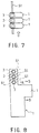
- Fig. 7 is a top view of a three-phase configuration of the switchgear 1
- Fig. 8 is a frontal view of Fig. 7 seen from the direction of the arrow.
- the respective input members (bus-line connecting members) 3 of the molded switchgears 1 are arranged in such a manner that the bus-lines 51 do not overlap one another in the vertical direction.
- a separate metal mold is used to form area A in Fig. 8 for each phase in addition to the main metal mold which is used to form the vacuum valves 7 and 13 and other elements which make up the main body of the switchgear 1 as in the first embodiment.
- the length connecting the vacuum valve 7 within the main body and the fixed conductor 5 of the bus-line connecting member 3 are altered in accordance with the type of bus-line connecting member 3.
- the metal mold of the bus-line connecting member 3 it is possible to provide a switchgear molded en bloc and housing three phases in a rectangular floor area as in Fig. 7 without altering the circuit breaking, disconnecting and earthing functions.
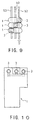
- the embodiment illustrated in Fig. 8 has been explained by modifying the metal mold in section A, but it goes without saying that a switchgear can easily be provided changing the mold of the output member (cable head receptor member) in section B and varying the direction on the cable side in the same manner.
- the input member 3 and output member 21 are changed phase by phase, so that it can be arranged in three phases without the bus-line and cable overlapping, thus allowing dead space to be minimized by virtue of the fact that the floor area is rectangular in shape.
- molding and set-up costs can be reduced simply by making partial alterations to the input and output members 3, 21 without any need to change the overall shape of the metal mold.
- cut parts costs because with the exception of the fixed conductor 5 all can be used irrespective of phase change.
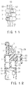
- the second embodiment has been described hitherto in terms of Figs. 7 and 8 where the bus-line is arranged vertically. However, it may also be arranged horizontally as in Figs. 9 and 10, with the same effect as in Figs. 7 and 8. It goes without saying that the same is true if it is arranged diagonally as in Figs. 11 and 12.
- the current sensor 55 can be a through-type transformer or Rogowsky coil, the latter being suitable where space is limited.
- the voltage sensor 57 all that needs to be arranged is an electrode or voltage divider with a ceramic capacitor, the voltage divider making use of the static capacity of the molded resin. Both the sensors are arranged around the charge member, and have a low voltage or earth member, which allows them to double as supporting member for the conductor, thus making it possible to reduce the numbers of such supporting members.
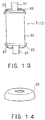
- Figs. 13-16 illustrate a third embodiment of the present invention.
- the third embodiment concerns the end shape of the vacuum valves 3 and 17 made of ceramic material as in Figs. 4 and 5 when they are molded en bloc.
- Fig. 13 is an outline cross-sectional view illustrating a vacuum valve 7 or 13 which is to be molded en bloc (the interior of the insulation tube has been omitted) .
- a movable side endplate 67 To a ceramic insulation tube 59 is sealed and attached within a vacuum a movable side endplate 67, to which in turn are attached a fixed side endplate 63 with fixed conductor 61, a movable side conductor 65 and bellows, which are not illustrared in the drawing.
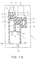
- FIG. 14 is an outline drawing of a the metal cap 69.
- the switchgear 1 is obtained.
- elastomer particles include Kureha EXL 2314 and Nihon Gosei Gomu (Japan Synthetic Rubber: JSR) FX 602.
- Kureha EXL 2314 is dispersed at an optimum ratio of 10% in an epoxy resin with fused silica particles as a filler and a glass transition temperature of 135°C, thus allowing the toughness value to rise from 1.8 Mpam 1 ⁇ 2 to 2.5 Mpam 1 ⁇ 2 With the aid of this resin a awitch gear with excellent properties of crack resistance was obtained. Molding was implemented by introducing the resin into the metal mold within a vacuum and performing primary curing in a curing oven.
- the mold may then be released and secondary curing performed, but instead resin to which an amine complex of boron trichloride had been added as an accelerator to promote reactivity in the epoxy resin at high temperatures was mixed in, the interior of the mold was decompressed at 130°C, and resin which had been defoamed at 50-6O°C poured in under pressure from the bottom of the mold, 30 minutes after which it was possible to release the mold. Secondary curing was then performed at 140-150°C to produce a switchgear.
- metal caps 69 are attached to both ends of the vacuum valves 7 and 13 to ensure that the point of maximum occurrence of heat stress due to the difference in the rate of linear expansion between the ceramic material and the resin comes between the vacuum valves 7 and 13 and the metal caps 69, thus allowing the vacuum valves 7 and 13 to be used irrespective of the end shapes thereof.
- rate of linear expansion in a resin employing a particulate bulking agent is roughly equivalent only to that of copper, its fracture toughness can be improved by dispersing about 10 phr 0.5-5 um fine elastomer particles.
- the amount of fine elastomer particles added varies according to particle size, type and particle size of the bulking agent, type of resin and other factors, apart from which both strength and elasticity vary, so that it is difficult to specify the optimum values.
- experiments performed by the authors of the present invention point to 5-20 phr as effective for molding the vacuum valves 7 and 13 en bloc. Inasmuch as it is a particulate bulking agent, foreign materials can also be removed during the process. It is also possible to pour the resin under pressure using a high-speed pressurized gel type mold, which yielded a uniform resin layer after curing.
- the addition of fine elastomer particles has the effect of lowering elasticity, thus facilitating a correspondinq reduction in heat stress.
- the fitting of metal caps 69 to the vacuum valves 7 and 13 means thet maximum stress is generated between the endplates and the caps. Even if peeling and cracking occur in this area, there is no effect in terms of insulation because the metal caps 69 and the endplates have the same potential. What is more, the fact that the fracture toughness of the molded resin increases means that any peeling or other faults occurring in this area do not escalate into fissures. If the vacuum valves 7 and 13 are molded without fitting any metal caps 69, fracture toughness is low with only silica or a similar particulate bulking agent.
- a buffer layer may be provided around the vacuum valves 7 and 13 or alternatively milled glass fibers or short fibers may be added to the bulking agent in order to improve toughness before molding.
- the former is time-consuming and troublesome, while with the latter it is often impossible to manage stability of quality. This is due to inability to control dispersion of the bulking agent when pouring the resin unser pressure as in high-speed molding, which leads to cracking. Moreover, any admixture of foreign bodies cannot be filtered out. With particulate molding materials on the other hand, foreign materials can be removed by filtering, and the bulking agent is dispersed even in high-speed molding, making it possible to provide a molded product of stable quality.
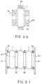
- the inside of the metal caps 69 was formed of the same resin as was used in molding.
- an elastomer 71 may also be used. With the elastomer 71, a roomtemperature vulcanizer may be packed in this space when the metal caps 69 are being fitted, or the elastomer may be molded beforehand and inserted before fitting the metal caps 69.
- maximum stress is generated at the interface between the tip of the elastomer 71 and the insulation tube 35, as a result of which it is best to cover the boundary with glass tape 73 in order to prevent cracking induced by peeling in this area.
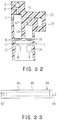
- the inlet 75 may be divided into 75a and 75b as illustrated in Fig. 16, and a plurality of deaeration members 77 and resin pools 79 provided in the metal molds 81.
- the vacuum valves 7, 13 and conductors 3, 5, 19 etc. are introduced into the mold 81 and resin 23 is poured in. Because the inlet 25 is divided into a plurality of inlets, the resin 23 can be packed uniformly without any risk of its not flowing and cavities remaining.
- the inlet 75 is divided into 75a and 75b within the mold 81, but this can also be effected outside the mold 81.
- the resin 23 is pressurized and heated, and is packed into the metal mold as the reaction proceeds, driving the air out in the meantime. However, a void is produced at the tip. This void and the air within the mold are extracted through the deaeration members 77 and resin pools 79. Were it not for the presence of these members 77 and 79, the pressure within the mold would rise as the resin 23 was packed, and a cavity would be generated at the top. For the purpose of extracting air it is preferable that the gap in the deaeration member be as wide as possible.
- the resin 23 which has been poured in will flow out through the deaeration members 77 or by way of the resin pools 79 through the deaeration members 77, and it will be impossible to obtain a satisfactory product.
- the first deaeration member on the bottom side it is preferable for the first deaeration member on the bottom side to be given a conical cross-section in order to make it easy for the resin 23 with voids to pass through. Meanwhile, the resin with voids is held in the resin pool 79. The gap in the deaeration member on the top side is made narrower. By the time the resin reaches this point, the reaction has proceeded, it has gelated and is stopped.
- deaeration members 77 and resin pools 79 are provided at a plurality of points according to the shape of the molded product so that the air and voids can be extracted. In this manner it was possible to obtain a switchgear 1 molded en bloc without any voids.
- the fourth embodiment relates to a method of molding an electrically conductive layer on the surface of the molded switchgear.
- the inner surface of the metal mold 81 is first processed with chlorine or a layer of mold release agent is baked on to the surface, after which a spray gun 84 filled with an electrically conductive coating agent 83 is used to form an electrically conductive layer 85 by spraying.
- Resin 23 is then poured into the metal mold 81, heated and cured to produce a molded product wherein the resin 23 and electrically conductive layer 85 form a single entity.
- the resin is poured in before the electrically conductive coating 83 has completely hardened, with the result that adhesion between the resin 23 and coating 83 is good, making it possible to obtain a molded product with an electrically conductive layer 85 on the surface thereof, the two forming a single entity.
- the process is simplified because the electrically conductive layer can be formed during the process of molding.
- Another method of forming the electrically conductive layer during high-speed molding is illustrated in Fig. 18.
- the resin 23 of the switchgear 1 is gelated and cured until there is no risk of losing its shape.
- the mold 81 and 81 is released slightly to create a gap d of 1-2 mm between the switchgear 1 and the mold 81, and the electrically conductive coating is poured in through an inlet 86.
- the metal mold 81 is then closed in such a manner as to allow the electrically conductive layer 85 to assume the prescribed thickness, and curing implemented until the electrically conductive layer 85 adheres to the switchgear 1.
- the metal mold 61 can be opened and closed easily, and the fact that the metal mold 81 is at a higher temperature than with regular molding means that it can be released in a short time.
- an electrically conductive coating 83 was used to form the electrically conductive layer 85, but instead of the electricallly conductive coating 83 is also possible to place a pre-impregnated epoxy electrically conductive sheet, that is to say, prepreg epoxy conductive sheet on the inner surface of the mold so that upon molding it creates an electrically conductive layer forming a single entity with the molded product.
- the metal mold 81 is released at the stage when the resin has gelated, and the surface of the molded product is covered with a prepreg conductive sheet, which is then heated and pressurized by closing the metal mold 81, it is possible to obtain a molded product wherein the electrically conductive layer adheres firmly to the surface of the molded product and forms a single entity with it.
- the fifth embodiment is a method of simultaneously molding the movable side conductors 9 and 15 in the molded switchgear illustrated in Fig. 2.
- the connecting member 11 to which a multi-contact band 87 has been attached is set together with the vacuum valves 7 and 13 and movable side conductors 9 and 15 in a metal mold not illustrated in the drawing. If the current capacity of the switchgear 1 is large, a plurality of multi-contact bands 87 is attached. In this case it is also possible to attach stress-mitigating metal caps to the tops and bottoms of the vacuum valves 7 and 13.
- the connecting member 11 is assembled in the metal mold with the moving side conductors 9 and 15 which are required to move accurately, it is possible to adjust the dimension with ease. Moreover, because the connecting member 11 is covered in resin 23 with a high degree of dielectric strength, only the movable side conductors 9 and 15 are exposed among the operational parts, allowing the insulation dimensions to be reduced.
- a fin 89 is attached to the surface of the switchgear 1 for use in cooling.
- Fig. 20 illustrates the sixth embodiment in outline.
- the outer surface of the switchgear 1 is shaped like a fin 89 in order to increase the surface area for use in cooling.
- the contact and connecting members in the switchgear 1 are the parts which generate heat, and this is the resistance loss of the conductors themselves, but it is particularly great in the contact and connecting members.
- the heat generated here is transferred to the surface by heat conduction in the resin, and is released there. The amount of heat released increases in proportion to the surface area. If the amount of heat released can be increased, the switchgear 1 can be made more compact.
- Fig. 20 shows an example where the cooling fin 89 fashioned as a single entity in the reain, but it is also possible to embed a piece of metal in the resin layer of the switchgear 1, and after molding to fix a metal cooling fin 89 to the metal embedded in the resin layer, thus attaching the metal cooling fin 89 to the surface of the molded switchgear 1.
- the metal cooling fin is attached to the surface of the molded switchgear 1 because this forms an electrically conductive layer.
- cooling efficiency is improved because the heat conductivity of the metal is better than that of the resin.
- Attaching a metal fin 89 to the switchgear 1 in the same mold allows the current capacity to be increased and makes it possible to reduce the types of vacuum valve used within. This makes for greater standardization and production efficiency. What is more, it is possible to standardize the metal fin 89, and by changing the number and location thereof to apply the same switchgear 1 to use with different current capacities, thus improving production efficiency. It should be added even greater efficacy of heat release can be achieved by painting the outer surface of the fin 89 black. Where use is not made of the metal fin 89, the metal embedded in the resin can be used to fix it to the board and for coupling to other phase switchgears.
- FIG. 21 illustrates a switchgear 1 wherein heat pipes 93 with heating fins 92 are fixed between a plurality of switchgears 1 and board-side plates 91.
- the use of heat pipes 93 allows the movement of heat to be made more uniform and improves the cooling efficiency of the cooling fins 92 attached to the heat pipes 93. Fixing them also to the boardside plates 91 means that these become cooling surfaces as well, thus facilitating a further increase in cooling efficiency. It goes without saying that this can be improved still further if the heat pipes 93 are connected to a heatexchanger.
- the seventh embodiment which is shown in outline in Fig. 22, permits the heat generated internally to be dispersed efficiently.
- the fixed conductors 5 and 17 of the vacuum valves 7 and 13 form a heat pipe connection conductor 94.
- Fig. 23 illustrates the heat pipe connection conductor 94 in outline.
- Within the copper or other conductor material 95 is a hollow section 96 into which is introduced a heat transport medium.
- One side forms a screw or other means of attachment 97, while the other side comprises a plug 98 through which the transport medium is introduced and which can be sealed and connected or attached.
- This heat pipe connection conductor 94 serves to connect the bus-line connection member 3 of the vacuum valves 7 and 13 to the cable head member 21, and is molded en bloc.
- the heat generated in the switchgear 1 at the point of connection of the vacuum valves 7 and 13 is large, but because the interior of the vacuum valves 7 and 13 comprises a vacuum, the heat is dispersed along the conductor and then released from the surface by way of the resin.
- Use of the heat pipe connection conductor 94 serves to ensure that the heat of the conductor is uniform, and that the same applies to the heat released from the conductor to the resin. In this manner it is possible to increase the area of heat release, thus improving the cooling efficiency.
- the method to which the present invention pertains makes it possible to supply in a cost-effective manner a switchgear wherein vacuum valves and other parts having the functions of a switchgear are molded en bloc, and which by virtue of the fact that an electrically conductive layer is provided on the surface thereof is compact and exhibits excellent cooling efficiency, productivity and crack resistance without resorting to the use of SP6 gas.
Landscapes
- Engineering & Computer Science (AREA)
- Power Engineering (AREA)
- High-Tension Arc-Extinguishing Switches Without Spraying Means (AREA)
- Gas-Insulated Switchgears (AREA)
Applications Claiming Priority (2)
| Application Number | Priority Date | Filing Date | Title |
|---|---|---|---|
| JP34206699 | 1999-12-01 | ||
| JP34206699A JP3845534B2 (ja) | 1999-12-01 | 1999-12-01 | スイッチギヤ |
Publications (3)
| Publication Number | Publication Date |
|---|---|
| EP1107409A1 true EP1107409A1 (fr) | 2001-06-13 |
| EP1107409A8 EP1107409A8 (fr) | 2001-11-14 |
| EP1107409B1 EP1107409B1 (fr) | 2010-07-07 |
Family
ID=18350903
Family Applications (1)
| Application Number | Title | Priority Date | Filing Date |
|---|---|---|---|
| EP00126303A Expired - Lifetime EP1107409B1 (fr) | 1999-12-01 | 2000-12-01 | Interrupteur et son procédé de fabrication |
Country Status (5)
| Country | Link |
|---|---|
| US (1) | US6897396B2 (fr) |
| EP (1) | EP1107409B1 (fr) |
| JP (1) | JP3845534B2 (fr) |
| CN (1) | CN1201357C (fr) |
| DE (1) | DE60044634D1 (fr) |
Cited By (14)
| Publication number | Priority date | Publication date | Assignee | Title |
|---|---|---|---|---|
| EP1343233A2 (fr) * | 2002-03-06 | 2003-09-10 | Kabushiki Kaisha Toshiba | Installation de commutation |
| NL1020581C2 (nl) * | 2002-05-13 | 2003-11-14 | Holec Holland Nv | Schakelinstallatie voorzien van elektrisch isolerende barriÞre. |
| US6897396B2 (en) | 1999-12-01 | 2005-05-24 | Kabushiki Kaisha Toshiba | Switch gear and method of manufacturing thereof |
| WO2006092380A1 (fr) * | 2005-03-03 | 2006-09-08 | Siemens Aktiengesellschaft | Appareil de coupure a caloduc |
| WO2007022931A1 (fr) * | 2005-08-22 | 2007-03-01 | Abb Technology Ag | Procede de fabrication de poles d'interrupteur destines a des dispositifs de commutation basse, moyenne et haute frequence et pole d'interrupteur |
| WO2007055830A2 (fr) * | 2005-10-28 | 2007-05-18 | S & C Electric Company | Ensemble interrupteur de circuits et son procédé de réalisation |
| WO2008116432A1 (fr) * | 2007-03-28 | 2008-10-02 | Siemens Aktiengesellschaft | Commutateur électrique |
| FR2925755A1 (fr) * | 2007-12-21 | 2009-06-26 | Schneider Electric Ind Sas | Isolation d'un dispositif de coupure de type ampoule a vide par surmoulage |
| EP2107659A1 (fr) * | 2008-04-01 | 2009-10-07 | Zurecon AG | Barre omnibus |
| RU2447536C2 (ru) * | 2010-07-06 | 2012-04-10 | Федеральное государственное унитарное предприятие "Всероссийский электротехнический институт имени В.И. Ленина" | Устройство управляемой коммутации |
| EP2458697A3 (fr) * | 2010-11-30 | 2014-01-01 | Hitachi Ltd. | Unité de commutation et appareil de commutation équipé de celle-ci |
| EP2858082A4 (fr) * | 2012-05-29 | 2016-02-24 | Hitachi Ltd | Unité de commutation ou équipement de commutation |
| EP3109880A1 (fr) * | 2015-06-22 | 2016-12-28 | ABB Schweiz AG | Piece polaire a moyenne ou basse tension avec au moins un element dissipateur de chaleur |
| WO2018054615A1 (fr) * | 2016-09-23 | 2018-03-29 | Siemens Aktiengesellschaft | Ensemble manchon de câble interruptible |
Families Citing this family (36)
| Publication number | Priority date | Publication date | Assignee | Title |
|---|---|---|---|---|
| JP2003203546A (ja) * | 2002-01-09 | 2003-07-18 | Toshiba Corp | モールド真空開閉器 |
| MXPA02004309A (es) * | 2002-04-30 | 2003-11-06 | Jose Manuel Flores Jauregui | Sistema de proteccion y control monofasico de alta tension con aislamiento seco. |
| US6888086B2 (en) * | 2002-09-30 | 2005-05-03 | Cooper Technologies Company | Solid dielectric encapsulated interrupter |
| US7304262B2 (en) * | 2003-04-25 | 2007-12-04 | Cooper Technologies Company | Vacuum encapsulation having an empty chamber |
| DE50304860D1 (de) * | 2003-07-11 | 2006-10-12 | Abb Research Ltd | Hochleistungsschalter mit Kühlrippenanordnung |
| JP4159938B2 (ja) * | 2003-07-25 | 2008-10-01 | 株式会社東芝 | モールド電気機器およびそのモールド方法 |
| DE102004031089B4 (de) * | 2004-06-28 | 2012-08-30 | Abb Technology Ag | Vakuumschaltkammer sowie Verfahren zur Herstellung derselben |
| JP4162664B2 (ja) * | 2005-02-22 | 2008-10-08 | 株式会社日立製作所 | 真空スイッチギヤ |
| JP4660303B2 (ja) * | 2005-07-12 | 2011-03-30 | 株式会社東芝 | 固体絶縁スイッチギヤ |
| JP4197702B2 (ja) | 2006-01-31 | 2008-12-17 | 株式会社日立製作所 | 真空絶縁スイッチギヤ |
| JP2008075069A (ja) | 2006-08-23 | 2008-04-03 | Toshiba Corp | 注型樹脂組成物およびそれを用いた絶縁材料、絶縁構造体 |
| US7807074B2 (en) * | 2006-12-12 | 2010-10-05 | Honeywell International Inc. | Gaseous dielectrics with low global warming potentials |
| JP4760741B2 (ja) * | 2007-03-19 | 2011-08-31 | 三菱電機株式会社 | 真空遮断器 |
| JP4832352B2 (ja) * | 2007-04-05 | 2011-12-07 | 株式会社日立製作所 | 樹脂モールド真空バルブ |
| EP1983623A1 (fr) * | 2007-04-18 | 2008-10-22 | Eaton Electric B.V. | Agencement de refroidissement de conducteur dans une installation électrique |
| JP4940018B2 (ja) * | 2007-05-15 | 2012-05-30 | 株式会社東芝 | 固体絶縁スイッチギヤ |
| US7902480B2 (en) * | 2007-06-13 | 2011-03-08 | Hitachi, Ltd. | Vacuum insulated switchgear |
| EP2071687A1 (fr) * | 2007-12-10 | 2009-06-17 | ABB Technology AG | Ensemble de commutation moyenne tension ou haute tension |
| ATE497246T1 (de) * | 2008-09-01 | 2011-02-15 | Abb Technology Ag | Niederspannungs-, mittelspannungs- oder hochspannungsanordnung |
| JP5756082B2 (ja) * | 2009-04-02 | 2015-07-29 | ハンツマン・アドヴァンスト・マテリアルズ・(スイッツランド)・ゲーエムベーハー | ダイレクトオーバーモールディング |
| JP4906892B2 (ja) * | 2009-08-12 | 2012-03-28 | 株式会社日立製作所 | スイッチギヤ |
| JP5292225B2 (ja) * | 2009-08-26 | 2013-09-18 | 株式会社東芝 | モールド真空バルブ |
| JP5431220B2 (ja) * | 2010-03-19 | 2014-03-05 | 株式会社東芝 | 固体絶縁スイッチギヤの放熱装置 |
| ES2649899T3 (es) * | 2010-07-07 | 2018-01-16 | Siemens Ltd. | Un aislador eléctrico |
| JP2012231576A (ja) * | 2011-04-25 | 2012-11-22 | Toshiba Corp | ガス絶縁スイッチギヤ |
| JP5749565B2 (ja) * | 2011-05-19 | 2015-07-15 | 株式会社東芝 | 樹脂モールド真空バルブ |
| US9177742B2 (en) | 2011-10-18 | 2015-11-03 | G & W Electric Company | Modular solid dielectric switchgear |
| CN104201041B (zh) * | 2014-08-15 | 2015-10-21 | 浙江道笃智能开关有限公司 | 组合固封极柱及其工作原理 |
| EP3185378B1 (fr) * | 2014-08-20 | 2019-07-03 | Kabushiki Kaisha Toshiba | Dispositif de dégagement de chaleur pour dispositif à isolation solide |
| CN104377073B (zh) * | 2014-12-05 | 2017-10-03 | 北京合锐清合电气有限公司 | 接地开关及基于该接地开关的固体绝缘环网柜 |
| CN104701064B (zh) * | 2015-03-26 | 2015-12-09 | 江苏现代电力科技股份有限公司 | 基于柔性分合闸技术的智能集成中压交流真空开关设备 |
| JP6968764B2 (ja) * | 2018-08-07 | 2021-11-17 | 株式会社日立産機システム | 真空開閉器及びその製造方法 |
| CN110794269B (zh) * | 2019-11-07 | 2021-09-07 | 云南电网有限责任公司电力科学研究院 | 一种绿色绝缘气体绝缘强度计算方法 |
| KR102460366B1 (ko) * | 2020-07-01 | 2022-11-01 | 한국전력공사 | 진공차단기 결상 보호 시스템 |
| WO2023281574A1 (fr) * | 2021-07-05 | 2023-01-12 | 三菱電機株式会社 | Procédé servant à la fabrication d'une soupape à vide |
| WO2023218695A1 (fr) * | 2022-05-10 | 2023-11-16 | 三菱電機株式会社 | Barre omnibus isolée solide |
Citations (3)
| Publication number | Priority date | Publication date | Assignee | Title |
|---|---|---|---|---|
| WO1986000464A1 (fr) * | 1984-06-21 | 1986-01-16 | The Electricity Council | Dispositif commutateur a haute tension |
| WO1999018591A1 (fr) * | 1997-10-03 | 1999-04-15 | Hitachi, Ltd. | Appareil de coupure sous vide |
| US5917167A (en) * | 1996-09-13 | 1999-06-29 | Cooper Industries, Inc. | Encapsulated vacuum interrupter and method of making same |
Family Cites Families (8)
| Publication number | Priority date | Publication date | Assignee | Title |
|---|---|---|---|---|
| US3513425A (en) * | 1969-05-21 | 1970-05-19 | Gen Electric | Modular electrical conductor termination system |
| US3812314A (en) * | 1971-08-23 | 1974-05-21 | Gen Electric | High power electrical bushing having a vacuum switch encapsulated therein |
| US3955167A (en) * | 1975-01-08 | 1976-05-04 | Mcgraw-Edison Company | Encapsulated vacuum fuse assembly |
| US4982059A (en) * | 1990-01-02 | 1991-01-01 | Cooper Industries, Inc. | Axial magnetic field interrupter |
| US5387772A (en) * | 1993-11-01 | 1995-02-07 | Cooper Industries, Inc. | Vacuum switch |
| US5597992A (en) * | 1994-12-09 | 1997-01-28 | Cooper Industries, Inc. | Current interchange for vacuum capacitor switch |
| JP3623333B2 (ja) | 1997-01-28 | 2005-02-23 | 株式会社東芝 | 受変電設備装置 |
| JP3845534B2 (ja) | 1999-12-01 | 2006-11-15 | 株式会社東芝 | スイッチギヤ |
-
1999
- 1999-12-01 JP JP34206699A patent/JP3845534B2/ja not_active Expired - Fee Related
-
2000
- 2000-12-01 US US09/726,411 patent/US6897396B2/en not_active Expired - Lifetime
- 2000-12-01 CN CNB001347438A patent/CN1201357C/zh not_active Expired - Fee Related
- 2000-12-01 EP EP00126303A patent/EP1107409B1/fr not_active Expired - Lifetime
- 2000-12-01 DE DE60044634T patent/DE60044634D1/de not_active Expired - Lifetime
Patent Citations (4)
| Publication number | Priority date | Publication date | Assignee | Title |
|---|---|---|---|---|
| WO1986000464A1 (fr) * | 1984-06-21 | 1986-01-16 | The Electricity Council | Dispositif commutateur a haute tension |
| US5917167A (en) * | 1996-09-13 | 1999-06-29 | Cooper Industries, Inc. | Encapsulated vacuum interrupter and method of making same |
| WO1999018591A1 (fr) * | 1997-10-03 | 1999-04-15 | Hitachi, Ltd. | Appareil de coupure sous vide |
| EP1028447A1 (fr) * | 1997-10-03 | 2000-08-16 | Hitachi, Ltd. | Appareil de coupure sous vide |
Cited By (28)
| Publication number | Priority date | Publication date | Assignee | Title |
|---|---|---|---|---|
| US6897396B2 (en) | 1999-12-01 | 2005-05-24 | Kabushiki Kaisha Toshiba | Switch gear and method of manufacturing thereof |
| EP1343233A3 (fr) * | 2002-03-06 | 2004-12-22 | Kabushiki Kaisha Toshiba | Installation de commutation |
| EP1343233A2 (fr) * | 2002-03-06 | 2003-09-10 | Kabushiki Kaisha Toshiba | Installation de commutation |
| AU2003235516B8 (en) * | 2002-05-13 | 2009-08-06 | Eaton Electric N.V. | Switching installation provided with an electrically insulating barrier |
| NL1020581C2 (nl) * | 2002-05-13 | 2003-11-14 | Holec Holland Nv | Schakelinstallatie voorzien van elektrisch isolerende barriÞre. |
| WO2003096504A1 (fr) * | 2002-05-13 | 2003-11-20 | Eaton Electric N.V. | Installation de commutation pourvue d'une barriere d'isolation electrique |
| AU2003235516B2 (en) * | 2002-05-13 | 2007-07-12 | Eaton Electric N.V. | Switching installation provided with an electrically insulating barrier |
| US7310221B2 (en) | 2002-05-13 | 2007-12-18 | Eaton Electric N.V. | Switching installation provided with an electrically insulating barrier |
| WO2006092380A1 (fr) * | 2005-03-03 | 2006-09-08 | Siemens Aktiengesellschaft | Appareil de coupure a caloduc |
| WO2007022931A1 (fr) * | 2005-08-22 | 2007-03-01 | Abb Technology Ag | Procede de fabrication de poles d'interrupteur destines a des dispositifs de commutation basse, moyenne et haute frequence et pole d'interrupteur |
| EP3826045A1 (fr) * | 2005-08-22 | 2021-05-26 | ABB Schweiz AG | Procédé de fabrication de pièces de pôle d'interrupteur pour installation de moyenne et haute tension |
| US7852180B2 (en) | 2005-08-22 | 2010-12-14 | Abb Technology Ag | Method for producing breaker pole parts for low-voltage, medium-voltage and high-voltage switchgear assemblies, and breaker pole part itself |
| US8272127B2 (en) | 2005-10-28 | 2012-09-25 | S&C Electric Company | Method of making a circuit interrupting device |
| CN101297387B (zh) * | 2005-10-28 | 2011-08-10 | 施恩禧电气有限公司 | 电路断流器组件 |
| WO2007055830A2 (fr) * | 2005-10-28 | 2007-05-18 | S & C Electric Company | Ensemble interrupteur de circuits et son procédé de réalisation |
| WO2007055830A3 (fr) * | 2005-10-28 | 2007-08-09 | S & C Electric Co | Ensemble interrupteur de circuits et son procédé de réalisation |
| AU2006312152B2 (en) * | 2005-10-28 | 2011-08-25 | S & C Electric Company | Circuit interrupter assembly and method of making the same |
| WO2008116432A1 (fr) * | 2007-03-28 | 2008-10-02 | Siemens Aktiengesellschaft | Commutateur électrique |
| WO2009106731A3 (fr) * | 2007-12-21 | 2009-10-22 | Schneider Electric Industries Sas | Isolation d'un dispositif de coupure de type ampoule a vide par surmoulage |
| FR2925755A1 (fr) * | 2007-12-21 | 2009-06-26 | Schneider Electric Ind Sas | Isolation d'un dispositif de coupure de type ampoule a vide par surmoulage |
| WO2009106731A2 (fr) * | 2007-12-21 | 2009-09-03 | Schneider Electric Industries Sas | Isolation d'un dispositif de coupure de type ampoule a vide par surmoulage |
| EP2107659A1 (fr) * | 2008-04-01 | 2009-10-07 | Zurecon AG | Barre omnibus |
| RU2447536C2 (ru) * | 2010-07-06 | 2012-04-10 | Федеральное государственное унитарное предприятие "Всероссийский электротехнический институт имени В.И. Ленина" | Устройство управляемой коммутации |
| EP2458697A3 (fr) * | 2010-11-30 | 2014-01-01 | Hitachi Ltd. | Unité de commutation et appareil de commutation équipé de celle-ci |
| US8872054B2 (en) | 2010-11-30 | 2014-10-28 | Hitachi, Ltd. | Switch unit and switchgear equipped therewith |
| EP2858082A4 (fr) * | 2012-05-29 | 2016-02-24 | Hitachi Ltd | Unité de commutation ou équipement de commutation |
| EP3109880A1 (fr) * | 2015-06-22 | 2016-12-28 | ABB Schweiz AG | Piece polaire a moyenne ou basse tension avec au moins un element dissipateur de chaleur |
| WO2018054615A1 (fr) * | 2016-09-23 | 2018-03-29 | Siemens Aktiengesellschaft | Ensemble manchon de câble interruptible |
Also Published As
| Publication number | Publication date |
|---|---|
| US6897396B2 (en) | 2005-05-24 |
| CN1305208A (zh) | 2001-07-25 |
| EP1107409A8 (fr) | 2001-11-14 |
| US20010002666A1 (en) | 2001-06-07 |
| DE60044634D1 (de) | 2010-08-19 |
| JP2001160342A (ja) | 2001-06-12 |
| CN1201357C (zh) | 2005-05-11 |
| EP1107409B1 (fr) | 2010-07-07 |
| JP3845534B2 (ja) | 2006-11-15 |
Similar Documents
| Publication | Publication Date | Title |
|---|---|---|
| US6897396B2 (en) | Switch gear and method of manufacturing thereof | |
| CN101268536B (zh) | 用于低、中、高压开关设备的开关电极部件的制造方法以及开关电极部件本身 | |
| KR101249785B1 (ko) | 플러그-인 부싱, 및 이와 같은 부싱을 갖는 고전압 설비 | |
| US8178812B2 (en) | Insulation of a switchgear device of vacuum cartridge type by insert moulding | |
| EP1343233A2 (fr) | Installation de commutation | |
| JP4832352B2 (ja) | 樹脂モールド真空バルブ | |
| EP1571684A1 (fr) | Appareil de commutation à isolation, moulage de résine et son procédé de fabrication | |
| KR101091683B1 (ko) | 개폐기/차단기용 조립식 절연하우징 | |
| US20100314357A1 (en) | Resin-molded vacuum valve | |
| CN1224153C (zh) | 母线连接装置 | |
| US4037187A (en) | Metal clad insulating circuit breaker | |
| CN109791858B (zh) | 高压开关装置和带有高压开关装置的开关设备以及高压开关装置的制造方法 | |
| KR101501218B1 (ko) | 진공 인터럽터 및 도체용 전압 제어 스크린 | |
| JP2006049329A (ja) | スイッチギア | |
| JP2011055567A (ja) | スイッチギヤ及びその製造方法 | |
| JP7141377B2 (ja) | 鉄道車両用開閉器、及び、その製造方法 | |
| CN102306588B (zh) | 一种组合式真空灭弧室极柱 | |
| JPH0145685B2 (fr) | ||
| JP3833444B2 (ja) | モールド真空バルブ及びその製造方法 | |
| KR101283475B1 (ko) | 개폐기/차단기용 조립식 복합 절연 하우징 | |
| JP2001110287A (ja) | スイッチギア | |
| CN118039346A (zh) | 一种绕组出线接头的全绝缘处理方法及其装置 | |
| CN113851352A (zh) | 一种多重复合绝缘的复合绝缘极柱 | |
| JPH1080027A (ja) | 絶縁スペ−サ | |
| JP2006202666A (ja) | 注型絶縁導体およびその製造方法 |
Legal Events
| Date | Code | Title | Description |
|---|---|---|---|
| PUAI | Public reference made under article 153(3) epc to a published international application that has entered the european phase |
Free format text: ORIGINAL CODE: 0009012 |
|
| 17P | Request for examination filed |
Effective date: 20001201 |
|
| AK | Designated contracting states |
Kind code of ref document: A1 Designated state(s): CH DE LI |
|
| AX | Request for extension of the european patent |
Free format text: AL;LT;LV;MK;RO;SI |
|
| RIN1 | Information on inventor provided before grant (corrected) |
Inventor name: SEKIYA, HIROKI, C/O TOSHIBA CORPORATION Inventor name: ITO, YOSHIHIRO, C/O TOSHIBA CORPORATION Inventor name: MIYAGAWA, MASARU, C/O TOSHIBA CORPORATION Inventor name: SHIMIZU, TOSHIO, C/O TOSHIBA CORPORATION Inventor name: MAKISHIMA, SATOSHI, C/O TOSHIBA CORPORATION Inventor name: KINOSHITA, SUSUMU, C/O TOSHIBA CORPORATION |
|
| AKX | Designation fees paid |
Free format text: CH DE LI |
|
| 17Q | First examination report despatched |
Effective date: 20061013 |
|
| GRAP | Despatch of communication of intention to grant a patent |
Free format text: ORIGINAL CODE: EPIDOSNIGR1 |
|
| GRAS | Grant fee paid |
Free format text: ORIGINAL CODE: EPIDOSNIGR3 |
|
| GRAA | (expected) grant |
Free format text: ORIGINAL CODE: 0009210 |
|
| AK | Designated contracting states |
Kind code of ref document: B1 Designated state(s): CH DE LI |
|
| REG | Reference to a national code |
Ref country code: CH Ref legal event code: EP |
|
| REF | Corresponds to: |
Ref document number: 60044634 Country of ref document: DE Date of ref document: 20100819 Kind code of ref document: P |
|
| PLBE | No opposition filed within time limit |
Free format text: ORIGINAL CODE: 0009261 |
|
| STAA | Information on the status of an ep patent application or granted ep patent |
Free format text: STATUS: NO OPPOSITION FILED WITHIN TIME LIMIT |
|
| 26N | No opposition filed |
Effective date: 20110408 |
|
| REG | Reference to a national code |
Ref country code: DE Ref legal event code: R097 Ref document number: 60044634 Country of ref document: DE Effective date: 20110408 |
|
| REG | Reference to a national code |
Ref country code: CH Ref legal event code: PL |
|
| PG25 | Lapsed in a contracting state [announced via postgrant information from national office to epo] |
Ref country code: LI Free format text: LAPSE BECAUSE OF NON-PAYMENT OF DUE FEES Effective date: 20101231 Ref country code: CH Free format text: LAPSE BECAUSE OF NON-PAYMENT OF DUE FEES Effective date: 20101231 |
|
| PGFP | Annual fee paid to national office [announced via postgrant information from national office to epo] |
Ref country code: DE Payment date: 20161123 Year of fee payment: 17 |
|
| REG | Reference to a national code |
Ref country code: DE Ref legal event code: R119 Ref document number: 60044634 Country of ref document: DE |
|
| PG25 | Lapsed in a contracting state [announced via postgrant information from national office to epo] |
Ref country code: DE Free format text: LAPSE BECAUSE OF NON-PAYMENT OF DUE FEES Effective date: 20180703 |