EP1107360A2 - Steckverbinder zum Verteilen mindestens eines Potentials auf mehrere Anschlusskontake - Google Patents
Steckverbinder zum Verteilen mindestens eines Potentials auf mehrere Anschlusskontake Download PDFInfo
- Publication number
- EP1107360A2 EP1107360A2 EP00126029A EP00126029A EP1107360A2 EP 1107360 A2 EP1107360 A2 EP 1107360A2 EP 00126029 A EP00126029 A EP 00126029A EP 00126029 A EP00126029 A EP 00126029A EP 1107360 A2 EP1107360 A2 EP 1107360A2
- Authority
- EP
- European Patent Office
- Prior art keywords
- housing
- contact
- contacts
- contact strip
- connection contacts
- Prior art date
- Legal status (The legal status is an assumption and is not a legal conclusion. Google has not performed a legal analysis and makes no representation as to the accuracy of the status listed.)
- Granted
Links
- 238000009826 distribution Methods 0.000 title description 2
- 238000009413 insulation Methods 0.000 claims abstract description 19
- 239000004020 conductor Substances 0.000 claims abstract description 18
- 238000006073 displacement reaction Methods 0.000 claims abstract description 17
- 230000000295 complement effect Effects 0.000 claims abstract description 6
- 230000037431 insertion Effects 0.000 claims abstract 2
- 238000003780 insertion Methods 0.000 claims abstract 2
- 210000002105 tongue Anatomy 0.000 description 4
- 238000005192 partition Methods 0.000 description 3
- 238000004049 embossing Methods 0.000 description 2
- 239000002184 metal Substances 0.000 description 2
- 238000000034 method Methods 0.000 description 2
- 238000011161 development Methods 0.000 description 1
- 230000018109 developmental process Effects 0.000 description 1
- 238000004519 manufacturing process Methods 0.000 description 1
- 230000013011 mating Effects 0.000 description 1
Images



Classifications
-
- H—ELECTRICITY
- H01—ELECTRIC ELEMENTS
- H01R—ELECTRICALLY-CONDUCTIVE CONNECTIONS; STRUCTURAL ASSOCIATIONS OF A PLURALITY OF MUTUALLY-INSULATED ELECTRICAL CONNECTING ELEMENTS; COUPLING DEVICES; CURRENT COLLECTORS
- H01R31/00—Coupling parts supported only by co-operation with counterpart
- H01R31/02—Intermediate parts for distributing energy to two or more circuits in parallel, e.g. splitter
-
- H—ELECTRICITY
- H01—ELECTRIC ELEMENTS
- H01R—ELECTRICALLY-CONDUCTIVE CONNECTIONS; STRUCTURAL ASSOCIATIONS OF A PLURALITY OF MUTUALLY-INSULATED ELECTRICAL CONNECTING ELEMENTS; COUPLING DEVICES; CURRENT COLLECTORS
- H01R4/00—Electrically-conductive connections between two or more conductive members in direct contact, i.e. touching one another; Means for effecting or maintaining such contact; Electrically-conductive connections having two or more spaced connecting locations for conductors and using contact members penetrating insulation
- H01R4/24—Connections using contact members penetrating or cutting insulation or cable strands
- H01R4/2416—Connections using contact members penetrating or cutting insulation or cable strands the contact members having insulation-cutting edges, e.g. of tuning fork type
- H01R4/242—Connections using contact members penetrating or cutting insulation or cable strands the contact members having insulation-cutting edges, e.g. of tuning fork type the contact members being plates having a single slot
- H01R4/2425—Flat plates, e.g. multi-layered flat plates
Definitions
- the invention relates to a connector for distribution at least one potential on several connection contacts, with a contact strip with several connection contacts to connect with complementary contacts and with one Housing for receiving the contact strip with Contact chambers for receiving the connection contacts.
- connection contacts It is known to distribute one potential over several Connection contacts the connection contacts by means of a To connect the metal strip and the conductor who does that too distributing potential carries, to be soldered to the strip. This process is both labor intensive and not particularly reliable.
- the connector according to the invention it is from particular advantage that the cable simply into one Cable duct is inserted, then the contact strip from brought a first position into a second end position and thus the conductor with the insulation displacement contacts the contact strip and thus with all Connection contacts is connected.
- This technique is very easy to use and provides a high level of security the contacting of the conductor.
- connection contacts It is particularly advantageous to have several Provide insulation displacement contacts that over the Contact strips are connected to the connection contacts, because this enables a high current carrying capacity to be achieved can and the safety of insulation displacement contact is further increased.
- connection contacts in the corresponding Contact chamber locked can be done, for example take place on the connection contacts detent spring tongues are provided behind the corresponding projections in the Intervene in contact chambers.
- the housing has a hinged cover with which the cable duct is covered and the cable is protected. It is either possible to attach the hinged cover directly to the housing or provide a corresponding housing to which the Hinged lid is hinged.
- the Contact strips can be pre-assembled in the housing and a cable with an insulated conductor inserted later can be. But it is also possible that Contact the conductor using the insulation displacement contacts is carried out directly by a setting machine.
- the Connector has an integrated strain relief. This is done by the hinged lid with appropriate means, especially the ribs that engage in the cable jacket, ensured.
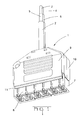
- Figure 1 shows a perspective view of the complete assembled connector.
- Figure 2 shows a first side view of the connector.
- Figure 3 shows a top view of the connector.
- Figure 4 shows a view of the mating face of the Connector.
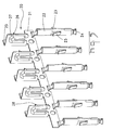
- Figure 5 shows a perspective view of a Contact strip.
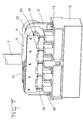
- Figure 6 shows a perspective view of a Housing with inserted contact strip in the first Position and introduced leader.
- Figure 7 shows a perspective view of the housing with inserted conductor and contact strip in end position.
- Figure 8 shows a perspective view of the Connector with housing and open hinged cover.
- Figure 1 shows a perspective view of a Connector 1 according to the invention around a distributor to distribute two potentials to 6x2 Pole of the connector.
- a cable 2 is provided with two conductors 3 and 4, each of one Insulation layer 5 and 6 are surrounded.
- the hinges 11 are designed as film hinges.
- the two Hinged covers 9, 10 firmly enclose the cable 2.
- the frame 8 of the surrounding housing 7 accommodates the actual housing 12.
- the housing 12 has contact chambers 13 which are in two Rows are arranged.
- FIGs 2, 3 and 4 are different views of the connector 1 according to the invention.
- FIG 5 is a perspective view of the Contact strip 20 shown, the part of Connector 1 is.
- the contact strip 20 has one Carrier strip 21, which is also used to transport the Metal strip in the manufacture of the contact strip serves.
- connection contacts 22 There are six on one side of the contact strip 20 Connection contacts 22.
- the connection contacts 22 are used for Connect with complementary contacts from complementary Connectors. They are essentially cylindrical trained and have on opposite sides each a detent spring tongue 23.
- the detent spring tongue 23 is used for Locking the connection contacts 22 in the contact chambers 13 of the housing 12.
- the contacts 22 are on their front end 24 slotted and thus have one resilient area for contacting a complementary Contact.
- insulation displacement contacts 25 On the side opposite the connection contacts 22 of the contact strip 20 there are insulation displacement contacts 25. These insulation displacement contacts 25 are essentially U-shaped formed with a slot 26 into which the conductor of the cable can be inserted. To have a higher rigidity reach, the insulation displacement contacts 25 have an embossing 27, which is also U-shaped and wherein the slot 26 between the legs of the embossing 27th located. The insulation displacement contacts 25 are out of the plane of the contact strip angled and essentially arranged perpendicular to it. The slot 26 has one Opening towards the connection contacts 22. To the Insulation displacement contacts are also locking teeth 28 intended. These serve to determine the Contact strip 20 in the housing.
- a housing 12 is shown in FIGS. 6 and 7 with Contact chambers 13 for receiving the connection contacts 22.
- the housing 12 has a partition 31 and is used for Contacting two conductors 3 and 4 of a cable 2. Die Conductors 3 and 4 are together with the insulation 5 and 6 in one cable duct 30 each on one side of the partition 31 inserted.
- the conductors 3 and 4 are U-shaped bent.
- the Contact strips 20 by pressure from the cable end 32 of the housing 12 brought here into its end position become.
- the locking teeth 28 engage in recesses 34 on.
- the housing 12, as shown in Figures 6 and 7, can now be inserted into the frame 8 of the surrounding housing 7 be and locked there with the locking lugs 35.
- the two Hinged covers 9 and 10 mutually have locking hooks and Locking openings 40 to 46 (see Figure 8), whereby a guaranteed secure holding of the two parts together is.
- the two parts enclose the cable 2 for sure.
- An additional rib 48 is in the recess 47 provided that penetrates into the cable jacket of cable 2 and an additional safeguard against tensile loads and represents a seal.
Landscapes
- Connector Housings Or Holding Contact Members (AREA)
- Details Of Connecting Devices For Male And Female Coupling (AREA)
- Coupling Device And Connection With Printed Circuit (AREA)
Abstract
Description
Claims (9)
- Steckverbinder zum Verteilen mindestens eines Potentials auf mehrere Anschlusskontaktedadurch gekennzeichnet, dass der Kontaktstreifen (20) zumindest einen Schneidklemmkontakt (25) zum Kontaktieren eines isolierten Leiters (3) aufweist, dass der Kontaktsteifen (20) in einer ersten Stellung im Gehäuse (12) verrastet ist, in der der Leiter (5) in einen Kabelkanal (30), der im Wesentlichen senkrecht zur Steckrichtung verläuft, einbringbar ist, dass der Kontaktstreifen (20) in einer zweiten Endstellung im Gehäuse (12) verrastbar ist, in der sämtliche Schneidklemmkontakte (25) den Leiter (3) kontaktieren.mit einem Kontaktstreifen (20)mit mehreren Anschlusskontakten (22) zum Verbinden mit komplementären Kontakten,mit einem Gehäuse (12) zur Aufnahme des Kontaktstreifens (20) mit Kontaktkammern (13) zur Aufnahme der Anschlusskontakte (22)
- Steckverbinder nach Anspruch 1, dadurch gekennzeichnet, dass der Kabelkanal (30) parallel zum Kontaktstreifen (20) verläuft.
- Steckverbinder nach Anspruch 1, dadurch gekennzeichnet, dass die Anschlusskontakte (22) in der Endstellung in den Kontaktkammern (13) gesichert sind.
- Steckverbinder nach Anspruch 1, dadurch gekennzeichnet, dass das Gehäuse (12) einen Klappdeckel (9,10) aufweist, zum Abdecken des Kabelkanals (30).
- Steckverbinder nach Anspruch 4, dadurch gekennzeichnet, dass der Klappdeckel (9,10) über ein Scharnier (11) mit dem Gehäuse(12) verbunden ist.
- Steckverbinder nach Anspruch 1, dadurch gekennzeichnet, dass sich auf einer Seite des Kontaktstreifens (20) die Anschlusskontakte (22) und auf der gegenüberliegenden Seite die Schneidklemmkontakte (25) befinden.
- Steckverbinder nach Anspruch 6, dadurch gekennzeichnet, dass die Schneidklemmkontakte (25) im Wesentlichen U-förmig ausgebildet sind und das 'U' sich zu den Anschlusskontakten (22) hin öffnet.
- Steckverbinder nach Anspruch 1, dadurch gekennzeichnet, dass das Gehäuse (12) auf gegenüberliegenden Seiten jeweils eine Aufnahme für einen Kontaktstreifen (20) aufweist.
- Steckverbinder nach Anspruch 8, dadurch gekennzeichnet, dass das Gehäuse (12) auf den gegenüberliegenden Seiten einen Klappdeckel ( 9,10) aufweist.
Priority Applications (1)
| Application Number | Priority Date | Filing Date | Title |
|---|---|---|---|
| EP20000126029 EP1107360B1 (de) | 1999-11-30 | 2000-11-29 | Steckverbinder zum Verteilen mindestens eines Potentials auf mehrere Anschlusskontake |
Applications Claiming Priority (4)
| Application Number | Priority Date | Filing Date | Title |
|---|---|---|---|
| DE99123721 | 1999-11-30 | ||
| EP99123721 | 1999-11-30 | ||
| EP99123721 | 1999-11-30 | ||
| EP20000126029 EP1107360B1 (de) | 1999-11-30 | 2000-11-29 | Steckverbinder zum Verteilen mindestens eines Potentials auf mehrere Anschlusskontake |
Publications (3)
| Publication Number | Publication Date |
|---|---|
| EP1107360A2 true EP1107360A2 (de) | 2001-06-13 |
| EP1107360A3 EP1107360A3 (de) | 2001-11-28 |
| EP1107360B1 EP1107360B1 (de) | 2003-05-07 |
Family
ID=26071620
Family Applications (1)
| Application Number | Title | Priority Date | Filing Date |
|---|---|---|---|
| EP20000126029 Expired - Lifetime EP1107360B1 (de) | 1999-11-30 | 2000-11-29 | Steckverbinder zum Verteilen mindestens eines Potentials auf mehrere Anschlusskontake |
Country Status (1)
| Country | Link |
|---|---|
| EP (1) | EP1107360B1 (de) |
Cited By (1)
| Publication number | Priority date | Publication date | Assignee | Title |
|---|---|---|---|---|
| CN107251340A (zh) * | 2015-02-10 | 2017-10-13 | 株式会社自动网络技术研究所 | 电源分配装置 |
Family Cites Families (2)
| Publication number | Priority date | Publication date | Assignee | Title |
|---|---|---|---|---|
| US4040703A (en) * | 1975-09-05 | 1977-08-09 | Amp Incorporated | Tri-lead cable connector |
| US4223971A (en) * | 1979-01-05 | 1980-09-23 | Amp Incorporated | Electrical wiring assembly and method |
-
2000
- 2000-11-29 EP EP20000126029 patent/EP1107360B1/de not_active Expired - Lifetime
Cited By (1)
| Publication number | Priority date | Publication date | Assignee | Title |
|---|---|---|---|---|
| CN107251340A (zh) * | 2015-02-10 | 2017-10-13 | 株式会社自动网络技术研究所 | 电源分配装置 |
Also Published As
| Publication number | Publication date |
|---|---|
| EP1107360A3 (de) | 2001-11-28 |
| EP1107360B1 (de) | 2003-05-07 |
Similar Documents
| Publication | Publication Date | Title |
|---|---|---|
| DE69210600T2 (de) | Steckbarer modularer verbinder und ueberbruchungsadapter | |
| DE69110294T2 (de) | Durchgehender schneidklemmenverbinder mit verschobenen reihen. | |
| DE3614592C1 (de) | Anschlussleiste fuer Kabeladern,insbesondere von Fernsprechkabeln | |
| DE69736583T2 (de) | Faseroptisches Steckersystem | |
| DE69823726T2 (de) | Elektrischer Kontakt | |
| DE112019003595T5 (de) | Elektrischer Steckverbinder, der unterschiedliche Dichtungsanordnungen akzeptiert | |
| DE102015200722A1 (de) | Steckverbindereinsatz und Steckverbinder für die Datenübertragung in Automobilen | |
| DE3306263C2 (de) | ||
| DE20319849U1 (de) | Steckverbindervorrichtung für mehradrige Flachbandkabel | |
| DE3938931C2 (de) | ||
| DE10130575A1 (de) | Steckverbinder | |
| DE3537722C2 (de) | ||
| DE602004004712T2 (de) | Verbinder mit Haltelement zum Festhalten eines Kabels | |
| DE10223271B4 (de) | Steckverbinder | |
| EP2417675A1 (de) | Steckersystemgehäuse für mehradrige kabel | |
| DE102017120180B3 (de) | Gewinkelter Steckverbinder | |
| DE202010010754U1 (de) | Steckverbinder mit Schneidklemmen und einem unverlierbaren Isolierkörper | |
| DE4105470C2 (de) | Elektrischer Steckverbinder | |
| DE60038472T2 (de) | Steckverbinder mit Kabelzugentlastung | |
| EP4324052A1 (de) | Kabelanschlusseinheit für eine anschlussdose | |
| EP1107360B1 (de) | Steckverbinder zum Verteilen mindestens eines Potentials auf mehrere Anschlusskontake | |
| DE3103455C2 (de) | Elektrischer Steckverbinder, insbesondere der Datentechnik | |
| DE2714158C3 (de) | Anschlußvorrichtung für ein vieladriges Rundkabel | |
| EP0092715A2 (de) | Zusatzverriegelung in einem Verbindergehäuse für einen elektrischen Verbinder | |
| DE1954997C3 (de) | Elektrische Steckvorrichtung |
Legal Events
| Date | Code | Title | Description |
|---|---|---|---|
| PUAI | Public reference made under article 153(3) epc to a published international application that has entered the european phase |
Free format text: ORIGINAL CODE: 0009012 |
|
| AK | Designated contracting states |
Kind code of ref document: A2 Designated state(s): DE FR GB NL Kind code of ref document: A2 Designated state(s): AT BE CH CY DE DK ES FI FR GB GR IE IT LI LU MC NL PT SE TR |
|
| AX | Request for extension of the european patent |
Free format text: AL;LT;LV;MK;RO;SI |
|
| PUAL | Search report despatched |
Free format text: ORIGINAL CODE: 0009013 |
|
| AK | Designated contracting states |
Kind code of ref document: A3 Designated state(s): AT BE CH CY DE DK ES FI FR GB GR IE IT LI LU MC NL PT SE TR |
|
| AX | Request for extension of the european patent |
Free format text: AL;LT;LV;MK;RO;SI |
|
| RIC1 | Information provided on ipc code assigned before grant |
Free format text: 7H 01R 4/24 A, 7H 01R 31/02 B |
|
| 17P | Request for examination filed |
Effective date: 20020228 |
|
| 17Q | First examination report despatched |
Effective date: 20020418 |
|
| AKX | Designation fees paid |
Free format text: DE FR GB NL |
|
| GRAH | Despatch of communication of intention to grant a patent |
Free format text: ORIGINAL CODE: EPIDOS IGRA |
|
| GRAH | Despatch of communication of intention to grant a patent |
Free format text: ORIGINAL CODE: EPIDOS IGRA |
|
| GRAA | (expected) grant |
Free format text: ORIGINAL CODE: 0009210 |
|
| AK | Designated contracting states |
Designated state(s): DE FR GB NL |
|
| PG25 | Lapsed in a contracting state [announced via postgrant information from national office to epo] |
Ref country code: NL Free format text: LAPSE BECAUSE OF FAILURE TO SUBMIT A TRANSLATION OF THE DESCRIPTION OR TO PAY THE FEE WITHIN THE PRESCRIBED TIME-LIMIT Effective date: 20030507 |
|
| REG | Reference to a national code |
Ref country code: GB Ref legal event code: FG4D Free format text: NOT ENGLISH |
|
| REF | Corresponds to: |
Ref document number: 50002058 Country of ref document: DE Date of ref document: 20030612 Kind code of ref document: P |
|
| GBT | Gb: translation of ep patent filed (gb section 77(6)(a)/1977) |
Effective date: 20030722 |
|
| NLV1 | Nl: lapsed or annulled due to failure to fulfill the requirements of art. 29p and 29m of the patents act | ||
| ET | Fr: translation filed | ||
| PLBE | No opposition filed within time limit |
Free format text: ORIGINAL CODE: 0009261 |
|
| STAA | Information on the status of an ep patent application or granted ep patent |
Free format text: STATUS: NO OPPOSITION FILED WITHIN TIME LIMIT |
|
| 26N | No opposition filed |
Effective date: 20040210 |
|
| REG | Reference to a national code |
Ref country code: DE Ref legal event code: R081 Ref document number: 50002058 Country of ref document: DE Owner name: TE CONNECTIVITY GERMANY GMBH, DE Free format text: FORMER OWNER: TYCO ELECTRONICS AMP GMBH, 64625 BENSHEIM, DE |
|
| REG | Reference to a national code |
Ref country code: FR Ref legal event code: PLFP Year of fee payment: 16 |
|
| REG | Reference to a national code |
Ref country code: FR Ref legal event code: CD Owner name: TE CONNECTIVITY GERMANY GMBH Effective date: 20151027 |
|
| REG | Reference to a national code |
Ref country code: FR Ref legal event code: PLFP Year of fee payment: 17 |
|
| REG | Reference to a national code |
Ref country code: FR Ref legal event code: PLFP Year of fee payment: 18 |
|
| REG | Reference to a national code |
Ref country code: FR Ref legal event code: PLFP Year of fee payment: 19 |
|
| PGFP | Annual fee paid to national office [announced via postgrant information from national office to epo] |
Ref country code: DE Payment date: 20191119 Year of fee payment: 20 |
|
| PGFP | Annual fee paid to national office [announced via postgrant information from national office to epo] |
Ref country code: FR Payment date: 20191014 Year of fee payment: 20 |
|
| PGFP | Annual fee paid to national office [announced via postgrant information from national office to epo] |
Ref country code: GB Payment date: 20191129 Year of fee payment: 20 |
|
| REG | Reference to a national code |
Ref country code: DE Ref legal event code: R071 Ref document number: 50002058 Country of ref document: DE |
|
| REG | Reference to a national code |
Ref country code: GB Ref legal event code: PE20 Expiry date: 20201128 |
|
| PG25 | Lapsed in a contracting state [announced via postgrant information from national office to epo] |
Ref country code: GB Free format text: LAPSE BECAUSE OF EXPIRATION OF PROTECTION Effective date: 20201128 |