EP1107042A1 - Lunettes - Google Patents
Lunettes Download PDFInfo
- Publication number
- EP1107042A1 EP1107042A1 EP00124016A EP00124016A EP1107042A1 EP 1107042 A1 EP1107042 A1 EP 1107042A1 EP 00124016 A EP00124016 A EP 00124016A EP 00124016 A EP00124016 A EP 00124016A EP 1107042 A1 EP1107042 A1 EP 1107042A1
- Authority
- EP
- European Patent Office
- Prior art keywords
- section
- holding
- pin
- glass
- glasses
- Prior art date
- Legal status (The legal status is an assumption and is not a legal conclusion. Google has not performed a legal analysis and makes no representation as to the accuracy of the status listed.)
- Granted
Links
Images


Classifications
-
- G—PHYSICS
- G02—OPTICS
- G02C—SPECTACLES; SUNGLASSES OR GOGGLES INSOFAR AS THEY HAVE THE SAME FEATURES AS SPECTACLES; CONTACT LENSES
- G02C1/00—Assemblies of lenses with bridges or browbars
- G02C1/02—Bridge or browbar secured to lenses without the use of rims
Definitions
- the invention relates to glasses with two glasses, one that Bridge element connecting glasses and one holding element for each glass and a bracket connected to the holding element or additional partially or completely enclosing the glasses Edge frame elements.
- One-piece spectacle frames are known, in which the Bracket-carrying holding elements and the bridge element between part of the rim for the two glasses the glasses are.
- partial edge versions are known where a fixation to the glasses by means of an adhesive connection he follows.
- Compounds are known in which the glass in each case is pierced and a pin of the bracket element or Holding element passed through a through hole in the glass and glued into it.
- Such an arrangement the eyeglass frame gives little flexibility in terms of design options glasses. For the glasses without rim frames there are stability problems with regard to the glasses of connections.
- WO96 / 30799 A1 an eyeglass frame is described in which the two temples and the nose bridge through a flexible, U-shaped Fastening element made of wire with the glasses are connected.
- One leg of the U-shaped fastener passes through a hole near the edge of the associated glass.
- the second leg running parallel to the first leg is due to the elastic preload of the legs to each other against the outer contour or into a recess in the outer contour of the glass pressed. This clamps the glass.
- WO 98/45748 A1 shows an eyeglass frame in which the fixation of the two brackets on the nose bridge to each Glass is done through wire sections, which one into a hole pin portion entering near the edge of the glass and a has a U-arch connected to it via an arch.
- the first leg of the U-bend lies in with the pin section one level and the second leg spans with the first leg a plane on that to the second between the pin portion and the first leg spanned plane perpendicular stands.
- the legs of the U-bend are on the outer edge of the glass on.
- DE 32 39 699 A1 are retaining clips that are U-shaped and that Partially enclose the lens on both sides.
- the Retainers consist of two parts that are outside the glass are clamped against each other by screws and the glass between clamp yourself in.
- the object of the present invention is to provide glasses, that match the respective ideas of the acquirers from one Construction kit of components with regard to holding elements, brackets and bridge elements as well as frame and partial frame can be put together are that allow an easy connection of the parts and moreover a connection in particular between the Bridge element and the glasses or associated edge frame elements and the holding element and the glasses or associated Allow edging elements that provide a favorable stability result in easier assembly. It also aims to connect be possible with external forces like this it is flexible that damage is largely avoided.
- the advantage of these training options is that simple Way a connection between the bridge element or Holding element and the glasses or an edge frame or partial edge frame can be achieved, so that fashionable elements individual design elements can be used or from a modular system can be put together.
- fashionable elements individual design elements can be used or from a modular system can be put together.
- the connections are also due to the Engagement of the holding section in a slot in vertical Loads extremely stable and with loads in a vertical Level extremely flexible.
- Holding element is made of a wire and the second pin portion and the second holding section by accordingly curved sections of the wire are formed.
- the holding element is also a design of the holding element as a molded part, be it as a die-cast part or injection-molded part made of plastic, possible, this the second pin portion and a holding portion are molded in the form of a web.
- a particularly favorable arrangement with regard to the connection results in an embodiment of the invention in that everyone first slot and / or second slot extends such that a imaginary extension of the respective slot over the associated one Glass or the associated frame elements to other glass or towards its edge frame elements, these cuts or crosses.
- All of the first and second slots are preferably parallel to one another arranged.
- a particularly favorable connection between the through hole and a pin section is achieved in that between both a sleeve is arranged. This is particularly so cheap when assigned to glasses without framing. It is however also an immediate definition of the first and / or second pin section in the associated first or second Through hole possible with an adhesive.
- a sleeve is provided, this is in the associated hole can be fixed either with a press fit or with an adhesive.
- the first or second pin section can also be in the associated sleeve additionally fixed by means of an adhesive become.
- the pin section for example, to form a thickening so that this after passing the cone section through the Sleeve, this engages behind. But there can also be additional ones non-positive surface designs on the pin section be provided.
- a round wire is preferably chosen, although others are also Wire cross sections are possible. It is particularly favorable if a highly flexible material, for example titanium or a titanium-containing one Material is used. To the design variants too increase, the wire can be at least partially coated or coated or be provided with different color applications.
- a visually favorable design results from the use a wire if the first pin section and / or the second Pin section each from the front of the glass or of the edge frame element into the associated first or second Through hole is inserted.
- the section between the Holding section and the pin section is visible.
- the overall design results in an attractive design. It is also an introduction of the tenon section from the back of the glass or of the edge frame element possible.
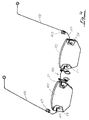
- FIG. 1 shows a first embodiment the glasses according to the invention can be seen.
- This comprises the two glasses 1 and 2, the glass 1 the right Represents eye-attributable glass.
- the two glasses 1, 2 are directly connected to each other by a bridge element 3.
- connection of the bridge element 3 with the glass 1 is exemplary also for the connection with the glass 2 based on the illustrations of Figure 2 explained in more detail.
- the bridge element 3 has a bridge section 8 on which one downward and then back again wire section directed above.
- the nose pad element 4 fixed.
- the wire is connected to it again angled by about 90 ° and runs from there again angled with the arch section 10. This merges into the first pin section 11.
- the first tenon section 11 also runs approximately at right angles to the holding section 9 so that it has the first holding section 9 at a distance crosses at right angles.
- a first through hole 12 is provided, which extends through the thickness of the first glass 1.
- this first through hole 12 is a first Inserted sleeve 13 and for example with the first glass 1st glued.
- the first sleeve 13 can also be one on the Front 15 of the first glass 1, lenticular Have thickening.
- the bridge element 3 is the first Glass 1 associated first pin portion 11 in the sleeve bore 14 introduced and in this for example by means of a Glue set. Starting from the edge area on the nose side 16, a slit 17 is worked into the first glass 1, which is slight is larger than the diameter of the bridge element 3 forming wire.
- the bridge element 3 is with its first Holding section 9 is not fixed in this first slot 17, giving flexibility of connection in this area is. This means that when the first glass 1 is loaded the front 15 a free movement between the first holding portion 9 and the first glass 1 in the area of the first Slot 17 is possible.
- the first holding section takes over 9 vertical loads on the narrow side of the act on the first glass 1 from above.
- the first holding section 9 the bridge element 3 thus actively supports the first glass 1 since the edges of the slot 17 of the first glass 1 on the can support the first holding section 9.
- the connection of the Bridge element 3 with the second glass 2 corresponds to that previously described with respect to the first glass 2.
- the first slot 17 at a distance from the first Through hole 12 is arranged. It is essentially aligned horizontally so that it is at an imaginary Extension towards the second glass 2, cut it or would cross.
- connection shown in Figure 3 between the holding element 5 and the bracket 6 with which this is connected to the first glass 1 is the same as previously in connection with the bridge element 3 described.
- the holding element 5, to which the bracket 6 is connected by means of the hinge 7 is connected, has a double starting from hinge 7 area angled in one plane, that with the second Holding section 18 ends.
- the holding element formed from a wire at right angles in the plane remaining angled.
- the second pin section 20 connected by means of a second arc section 19.
- the second pin section 20 runs in relation to the second holding section 18 so that it is at a distance crosses at right angles. Suitable for this are in the first glass 1 in Area of the bracket-side edge area 24 a second through hole 21, which runs through the thickness of the glass 1, and a second slot 23 which is parallel to the first Slit 17 runs, arranged.
- a second sleeve 22 which corresponds to the first sleeve 13, used. This is also in the area with the first glass 1 the second through hole 21 glued.
- the second sleeve 22 also has a sleeve bore in which the holding element 5 sits with the second pin section 20 and with this is connected by means of adhesive or friction or positive locking.
- Slot 23 In the arranged at a distance from the second through hole 21 Slot 23 is the holding element 5 with little play to the edges of the second slot 23 added, so that the second Holding section 18 actively supports the glass 1, but around an axis, which is arranged parallel to the axis of the hinge 7, a allows flexible adjustment or deformation of the holding element 5, which is also made from a thin flexible wire is.
- the second bracket to be assigned is by another corresponding holding element and in a corresponding manner with the associated second glass connected.
- FIG. 4 shows a representation of a pair of glasses, in which a modification 1, the bridge element 103 or the two holding elements 105, which are only mirror-inverted, with the associated glasses 101, 102 not immediately, but under Interposition of first and second border elements 25, 26 are connected.
- the through holes that are related with Figures 2 and 3 to define the bridge element and the holding element have been described and the associated Slots are not in the embodiment according to FIG. 4 directly associated with glasses 101 and 102, but with first and second edge frame elements 25 and 26, respectively 4 illustrated first and second edge frame elements 25, 26 can also be connected to each other so that the associated Glass 101, 102 all around on its edge or at least with respect to the top or bottom.
- Figures 5 and 6 show a further embodiment a bracket-side connection. Components with components of the Figure 3 match, are provided with reference numerals around the value 200 is increased, and described there.
- the connection differs from the connection according to FIG. 3 in that that the imaginary extension of the second holding section 218 intersects the second pin portion 220.
Applications Claiming Priority (2)
| Application Number | Priority Date | Filing Date | Title |
|---|---|---|---|
| DE19958005A DE19958005C1 (de) | 1999-12-02 | 1999-12-02 | Brille |
| DE19958005 | 1999-12-02 |
Publications (2)
| Publication Number | Publication Date |
|---|---|
| EP1107042A1 true EP1107042A1 (fr) | 2001-06-13 |
| EP1107042B1 EP1107042B1 (fr) | 2006-02-08 |
Family
ID=7931117
Family Applications (1)
| Application Number | Title | Priority Date | Filing Date |
|---|---|---|---|
| EP00124016A Expired - Lifetime EP1107042B1 (fr) | 1999-12-02 | 2000-11-04 | Lunettes |
Country Status (5)
| Country | Link |
|---|---|
| US (1) | US6439717B2 (fr) |
| EP (1) | EP1107042B1 (fr) |
| AT (1) | ATE317559T1 (fr) |
| DE (2) | DE19958005C1 (fr) |
| ES (1) | ES2257992T3 (fr) |
Cited By (7)
| Publication number | Priority date | Publication date | Assignee | Title |
|---|---|---|---|---|
| WO2002095481A2 (fr) * | 2001-05-22 | 2002-11-28 | Optische Werke G. Rodenstock | Lunettes |
| WO2003083554A2 (fr) * | 2002-04-03 | 2003-10-09 | Silhouette International Schmied Ag | Assemblage par liaison de forme entre une piece en fil metallique et un corps en matiere plastique moule par injection, en particulier pour lunettes |
| US6834954B2 (en) | 2002-08-28 | 2004-12-28 | Minima | Spectacles of the type without a surround |
| US7264348B2 (en) | 2004-08-19 | 2007-09-04 | Minima | Spectacles of the rimless type having hinge-less wire side-arms that are deformable in flexing |
| WO2008040754A1 (fr) * | 2006-10-04 | 2008-04-10 | Allison S.P.A. | Système destiné à fixer des éléments métalliques sur des lunettes sans monture |
| EP2053448A1 (fr) | 2007-10-26 | 2009-04-29 | Minima | Lunettes de type sans entourage à branches filaires |
| US7717554B2 (en) | 2006-04-20 | 2010-05-18 | Minima | Rimless eyeglasses having side branches essentially of wire structure |
Families Citing this family (6)
| Publication number | Priority date | Publication date | Assignee | Title |
|---|---|---|---|---|
| JP4104304B2 (ja) * | 2001-08-03 | 2008-06-18 | 増永眼鏡株式会社 | レンズ定置性の優れたリムレス眼鏡 |
| DE10240635A1 (de) * | 2002-09-03 | 2004-03-11 | Arvinmeritor Gmbh | Führungsmechanik für einen Deckel eines Schiebehebedachs |
| EP1531354A1 (fr) * | 2003-11-11 | 2005-05-18 | Anders Grove | Lunettes sans monture et partie charnière pour lunettes sans monture |
| US7971992B1 (en) | 2010-02-01 | 2011-07-05 | Brooks Jr Byron A | Eyewear with interchangeable components |
| US10831039B2 (en) * | 2018-02-08 | 2020-11-10 | Brent Sheldon | Flexible bridge assembly for rimless eyewear |
| CN112925113A (zh) * | 2021-02-02 | 2021-06-08 | 陈邦宋 | 一种便于更换镜片的眼镜 |
Citations (5)
| Publication number | Priority date | Publication date | Assignee | Title |
|---|---|---|---|---|
| EP0724178A1 (fr) * | 1994-08-12 | 1996-07-31 | MASUNAGA OPTICAL MFG. Co., LTD. | Lunettes sans cadre avec trois points de fixation pour les verres |
| EP0805369A1 (fr) * | 1996-05-03 | 1997-11-05 | Filospiave Group S.p.A. | Monture de lunettes constructivement simple et léger |
| WO1998040778A1 (fr) * | 1997-03-12 | 1998-09-17 | Cosmo Line Optic S.A.S. Di Gaiga Rino E C. | Monture de lunettes constituee d'un fil metallique |
| US5997137A (en) * | 1998-08-12 | 1999-12-07 | The Hilsinger Company Lp | Modular eyewear assembly |
| WO2000026716A1 (fr) * | 1998-11-04 | 2000-05-11 | Microvision Optical, Inc. | Fixation d'un pont et d'une charniere de branche au verre de lunettes glace |
Family Cites Families (7)
| Publication number | Priority date | Publication date | Assignee | Title |
|---|---|---|---|---|
| DE3239699A1 (de) * | 1982-10-27 | 1984-05-03 | Klaus 7000 Stuttgart Hafner | Randlose brille |
| KR0159580B1 (ko) * | 1992-07-17 | 1999-05-01 | 마사루 무라이 | 안경 |
| DE69502077T2 (de) * | 1994-07-11 | 1998-10-15 | Bottega Arte Firenze Srl | Brillengestell |
| IT1280837B1 (it) * | 1995-03-31 | 1998-02-11 | Pietro Devercelli | Montatura perfezionata per occhiali. |
| DE69734979T2 (de) * | 1997-04-07 | 2006-08-17 | Polaris Inter Ab | Brille |
| US6024445A (en) * | 1998-11-04 | 2000-02-15 | Microvision Optical, Inc. | Single point attachment of bridge and temples to eyeglass lenses |
| US6007200A (en) * | 1999-03-08 | 1999-12-28 | Aoyama Gankyo Kabushiki Kaisha | Lens holding mechanism of rimless spectacles |
-
1999
- 1999-12-02 DE DE19958005A patent/DE19958005C1/de not_active Expired - Fee Related
-
2000
- 2000-11-04 ES ES00124016T patent/ES2257992T3/es not_active Expired - Lifetime
- 2000-11-04 EP EP00124016A patent/EP1107042B1/fr not_active Expired - Lifetime
- 2000-11-04 AT AT00124016T patent/ATE317559T1/de not_active IP Right Cessation
- 2000-11-04 DE DE50012185T patent/DE50012185D1/de not_active Expired - Fee Related
- 2000-11-30 US US09/726,630 patent/US6439717B2/en not_active Expired - Fee Related
Patent Citations (5)
| Publication number | Priority date | Publication date | Assignee | Title |
|---|---|---|---|---|
| EP0724178A1 (fr) * | 1994-08-12 | 1996-07-31 | MASUNAGA OPTICAL MFG. Co., LTD. | Lunettes sans cadre avec trois points de fixation pour les verres |
| EP0805369A1 (fr) * | 1996-05-03 | 1997-11-05 | Filospiave Group S.p.A. | Monture de lunettes constructivement simple et léger |
| WO1998040778A1 (fr) * | 1997-03-12 | 1998-09-17 | Cosmo Line Optic S.A.S. Di Gaiga Rino E C. | Monture de lunettes constituee d'un fil metallique |
| US5997137A (en) * | 1998-08-12 | 1999-12-07 | The Hilsinger Company Lp | Modular eyewear assembly |
| WO2000026716A1 (fr) * | 1998-11-04 | 2000-05-11 | Microvision Optical, Inc. | Fixation d'un pont et d'une charniere de branche au verre de lunettes glace |
Cited By (12)
| Publication number | Priority date | Publication date | Assignee | Title |
|---|---|---|---|---|
| WO2002095481A2 (fr) * | 2001-05-22 | 2002-11-28 | Optische Werke G. Rodenstock | Lunettes |
| WO2002095481A3 (fr) * | 2001-05-22 | 2003-04-24 | Rodenstock Optik G | Lunettes |
| WO2003083554A2 (fr) * | 2002-04-03 | 2003-10-09 | Silhouette International Schmied Ag | Assemblage par liaison de forme entre une piece en fil metallique et un corps en matiere plastique moule par injection, en particulier pour lunettes |
| WO2003083554A3 (fr) * | 2002-04-03 | 2004-03-11 | Silhouette Int Schmied Ag | Assemblage par liaison de forme entre une piece en fil metallique et un corps en matiere plastique moule par injection, en particulier pour lunettes |
| US7147322B2 (en) | 2002-04-03 | 2006-12-12 | Silhouette International Schmied Ag | Form-fitting connection between a piece of wire and an injection-molded plastic body, particularly for eyeglasses |
| CN1307464C (zh) * | 2002-04-03 | 2007-03-28 | 塞尔豪约特国际锻造股份公司 | 在金属丝件和注塑成型体之间的特别是用于眼镜的形锁合连接装置 |
| US6834954B2 (en) | 2002-08-28 | 2004-12-28 | Minima | Spectacles of the type without a surround |
| US7264348B2 (en) | 2004-08-19 | 2007-09-04 | Minima | Spectacles of the rimless type having hinge-less wire side-arms that are deformable in flexing |
| US7717554B2 (en) | 2006-04-20 | 2010-05-18 | Minima | Rimless eyeglasses having side branches essentially of wire structure |
| WO2008040754A1 (fr) * | 2006-10-04 | 2008-04-10 | Allison S.P.A. | Système destiné à fixer des éléments métalliques sur des lunettes sans monture |
| EP2053448A1 (fr) | 2007-10-26 | 2009-04-29 | Minima | Lunettes de type sans entourage à branches filaires |
| US7670000B2 (en) | 2007-10-26 | 2010-03-02 | Minima | Eyeglasses of the rimless type with wire branches |
Also Published As
| Publication number | Publication date |
|---|---|
| DE19958005C1 (de) | 2001-07-26 |
| US20010019395A1 (en) | 2001-09-06 |
| ES2257992T3 (es) | 2006-08-16 |
| EP1107042B1 (fr) | 2006-02-08 |
| DE50012185D1 (de) | 2006-04-20 |
| ATE317559T1 (de) | 2006-02-15 |
| US6439717B2 (en) | 2002-08-27 |
Similar Documents
| Publication | Publication Date | Title |
|---|---|---|
| EP1107042B1 (fr) | Lunettes | |
| CH689407A5 (de) | Randlose Brille. | |
| DE3224659A1 (de) | Brillengestell mit elastischen verbindungsteilen | |
| DE3105986A1 (de) | "brillengestell mit abnehmbarem stirnteil" | |
| DE3413872C2 (fr) | ||
| WO2011107410A1 (fr) | Paire de lunettes | |
| DE69817544T2 (de) | Monokularschirm für brille und verfahren zu seiner herstellung | |
| EP0978749A1 (fr) | Lunettes | |
| DE4314595A1 (de) | Rahmenlose Brille | |
| DE60018214T2 (de) | Vorrichtung zur befestigung zusätzlicher linsen auf brillen | |
| DE102004023840B3 (de) | Brille | |
| DE69918307T2 (de) | Modulare lesebrille | |
| DE10324417A1 (de) | Brillensystem | |
| EP0361547A2 (fr) | Monture de lunettes sans bord pour correction | |
| EP1550896B1 (fr) | Lunettes | |
| DE1227691B (de) | Brillenfassung mit Metallbuegel | |
| DE3149178C2 (de) | Nichtmetallische Brillenfassung mit justierbaren Seitenstegen | |
| EP0771434A1 (fr) | Dispositif permettant de fixer des bandes decoratives sur des verres de lunettes ou sur des montures | |
| DE2852199A1 (de) | Auswechselbare zierverblendung fuer brillenfassungen | |
| WO2003107074A1 (fr) | Lunettes, notamment lunettes sans monture a verres perces | |
| DE1939353U (de) | Brillengestell. | |
| WO2017121807A1 (fr) | Dispositif de fixation d'une branche, d'une charnière et/ou d'un pont d'une monture de lunettes à un verre de lunettes pour des lunettes sans cercles | |
| DE20318798U1 (de) | Hakenpolster zur Befestigung von Sonnengläsern an Augengläsern | |
| DE202006004764U1 (de) | Brille | |
| DE8312272U1 (de) | Brille |
Legal Events
| Date | Code | Title | Description |
|---|---|---|---|
| PUAI | Public reference made under article 153(3) epc to a published international application that has entered the european phase |
Free format text: ORIGINAL CODE: 0009012 |
|
| AK | Designated contracting states |
Kind code of ref document: A1 Designated state(s): AT BE CH CY DE DK ES FI FR GB GR IE IT LI LU MC NL PT SE TR |
|
| AX | Request for extension of the european patent |
Free format text: AL;LT;LV;MK;RO;SI |
|
| 17P | Request for examination filed |
Effective date: 20011205 |
|
| AKX | Designation fees paid |
Free format text: AT BE CH CY DE DK ES FI FR GB GR IE IT LI LU MC NL PT SE TR |
|
| 17Q | First examination report despatched |
Effective date: 20040526 |
|
| GRAP | Despatch of communication of intention to grant a patent |
Free format text: ORIGINAL CODE: EPIDOSNIGR1 |
|
| GRAS | Grant fee paid |
Free format text: ORIGINAL CODE: EPIDOSNIGR3 |
|
| GRAA | (expected) grant |
Free format text: ORIGINAL CODE: 0009210 |
|
| AK | Designated contracting states |
Kind code of ref document: B1 Designated state(s): AT CH DE ES FR GB IT LI NL |
|
| PG25 | Lapsed in a contracting state [announced via postgrant information from national office to epo] |
Ref country code: IT Free format text: LAPSE BECAUSE OF FAILURE TO SUBMIT A TRANSLATION OF THE DESCRIPTION OR TO PAY THE FEE WITHIN THE PRESCRIBED TIME-LIMIT;WARNING: LAPSES OF ITALIAN PATENTS WITH EFFECTIVE DATE BEFORE 2007 MAY HAVE OCCURRED AT ANY TIME BEFORE 2007. THE CORRECT EFFECTIVE DATE MAY BE DIFFERENT FROM THE ONE RECORDED. Effective date: 20060208 |
|
| REG | Reference to a national code |
Ref country code: GB Ref legal event code: FG4D Free format text: NOT ENGLISH |
|
| REG | Reference to a national code |
Ref country code: CH Ref legal event code: EP |
|
| REF | Corresponds to: |
Ref document number: 50012185 Country of ref document: DE Date of ref document: 20060420 Kind code of ref document: P |
|
| GBT | Gb: translation of ep patent filed (gb section 77(6)(a)/1977) |
Effective date: 20060518 |
|
| REG | Reference to a national code |
Ref country code: CH Ref legal event code: NV Representative=s name: PA ALDO ROEMPLER |
|
| REG | Reference to a national code |
Ref country code: ES Ref legal event code: FG2A Ref document number: 2257992 Country of ref document: ES Kind code of ref document: T3 |
|
| ET | Fr: translation filed | ||
| PLBI | Opposition filed |
Free format text: ORIGINAL CODE: 0009260 |
|
| PGFP | Annual fee paid to national office [announced via postgrant information from national office to epo] |
Ref country code: NL Payment date: 20061116 Year of fee payment: 7 |
|
| PGFP | Annual fee paid to national office [announced via postgrant information from national office to epo] |
Ref country code: FR Payment date: 20061117 Year of fee payment: 7 |
|
| PGFP | Annual fee paid to national office [announced via postgrant information from national office to epo] |
Ref country code: AT Payment date: 20061122 Year of fee payment: 7 |
|
| PGFP | Annual fee paid to national office [announced via postgrant information from national office to epo] |
Ref country code: CH Payment date: 20061123 Year of fee payment: 7 Ref country code: ES Payment date: 20061123 Year of fee payment: 7 Ref country code: GB Payment date: 20061123 Year of fee payment: 7 |
|
| PGFP | Annual fee paid to national office [announced via postgrant information from national office to epo] |
Ref country code: IT Payment date: 20061130 Year of fee payment: 7 |
|
| 26 | Opposition filed |
Opponent name: RICHTER, INA Effective date: 20061107 |
|
| PLAF | Information modified related to communication of a notice of opposition and request to file observations + time limit |
Free format text: ORIGINAL CODE: EPIDOSCOBS2 |
|
| PLAX | Notice of opposition and request to file observation + time limit sent |
Free format text: ORIGINAL CODE: EPIDOSNOBS2 |
|
| PLBB | Reply of patent proprietor to notice(s) of opposition received |
Free format text: ORIGINAL CODE: EPIDOSNOBS3 |
|
| PGFP | Annual fee paid to national office [announced via postgrant information from national office to epo] |
Ref country code: DE Payment date: 20070124 Year of fee payment: 7 |
|
| NLR1 | Nl: opposition has been filed with the epo |
Opponent name: RICHTER, INA |
|
| GBPC | Gb: european patent ceased through non-payment of renewal fee |
Effective date: 20071104 |
|
| PG25 | Lapsed in a contracting state [announced via postgrant information from national office to epo] |
Ref country code: CH Free format text: LAPSE BECAUSE OF NON-PAYMENT OF DUE FEES Effective date: 20071130 Ref country code: LI Free format text: LAPSE BECAUSE OF NON-PAYMENT OF DUE FEES Effective date: 20071130 |
|
| REG | Reference to a national code |
Ref country code: CH Ref legal event code: PL |
|
| NLV4 | Nl: lapsed or anulled due to non-payment of the annual fee |
Effective date: 20080601 |
|
| PG25 | Lapsed in a contracting state [announced via postgrant information from national office to epo] |
Ref country code: AT Free format text: LAPSE BECAUSE OF NON-PAYMENT OF DUE FEES Effective date: 20071104 |
|
| PG25 | Lapsed in a contracting state [announced via postgrant information from national office to epo] |
Ref country code: DE Free format text: LAPSE BECAUSE OF NON-PAYMENT OF DUE FEES Effective date: 20080603 Ref country code: NL Free format text: LAPSE BECAUSE OF NON-PAYMENT OF DUE FEES Effective date: 20080601 |
|
| REG | Reference to a national code |
Ref country code: FR Ref legal event code: ST Effective date: 20080930 |
|
| PG25 | Lapsed in a contracting state [announced via postgrant information from national office to epo] |
Ref country code: GB Free format text: LAPSE BECAUSE OF NON-PAYMENT OF DUE FEES Effective date: 20071104 |
|
| REG | Reference to a national code |
Ref country code: ES Ref legal event code: FD2A Effective date: 20071105 |
|
| PG25 | Lapsed in a contracting state [announced via postgrant information from national office to epo] |
Ref country code: FR Free format text: LAPSE BECAUSE OF NON-PAYMENT OF DUE FEES Effective date: 20071130 Ref country code: ES Free format text: LAPSE BECAUSE OF NON-PAYMENT OF DUE FEES Effective date: 20071105 |
|
| PG25 | Lapsed in a contracting state [announced via postgrant information from national office to epo] |
Ref country code: IT Free format text: LAPSE BECAUSE OF NON-PAYMENT OF DUE FEES Effective date: 20071104 |
|
| PLBD | Termination of opposition procedure: decision despatched |
Free format text: ORIGINAL CODE: EPIDOSNOPC1 |
|
| PLBM | Termination of opposition procedure: date of legal effect published |
Free format text: ORIGINAL CODE: 0009276 |
|
| STAA | Information on the status of an ep patent application or granted ep patent |
Free format text: STATUS: OPPOSITION PROCEDURE CLOSED |
|
| 27C | Opposition proceedings terminated |
Effective date: 20100211 |