EP1103760A2 - Wasserdichte Struktur einer Glühlampenfassung mit Klemmanschluss - Google Patents
Wasserdichte Struktur einer Glühlampenfassung mit Klemmanschluss Download PDFInfo
- Publication number
- EP1103760A2 EP1103760A2 EP00121181A EP00121181A EP1103760A2 EP 1103760 A2 EP1103760 A2 EP 1103760A2 EP 00121181 A EP00121181 A EP 00121181A EP 00121181 A EP00121181 A EP 00121181A EP 1103760 A2 EP1103760 A2 EP 1103760A2
- Authority
- EP
- European Patent Office
- Prior art keywords
- clamp
- connection
- light bulb
- connecting device
- incandescent lamp
- Prior art date
- Legal status (The legal status is an assumption and is not a legal conclusion. Google has not performed a legal analysis and makes no representation as to the accuracy of the status listed.)
- Withdrawn
Links
Images




Classifications
-
- A—HUMAN NECESSITIES
- A47—FURNITURE; DOMESTIC ARTICLES OR APPLIANCES; COFFEE MILLS; SPICE MILLS; SUCTION CLEANERS IN GENERAL
- A47G—HOUSEHOLD OR TABLE EQUIPMENT
- A47G33/00—Religious or ritual equipment in dwelling or for general use
- A47G33/04—Christmas trees
- A47G33/10—Fastening devices or clamps for Christmas tree decorations
- A47G33/105—Fastening means for Christmas tree candle holders
-
- F—MECHANICAL ENGINEERING; LIGHTING; HEATING; WEAPONS; BLASTING
- F21—LIGHTING
- F21V—FUNCTIONAL FEATURES OR DETAILS OF LIGHTING DEVICES OR SYSTEMS THEREOF; STRUCTURAL COMBINATIONS OF LIGHTING DEVICES WITH OTHER ARTICLES, NOT OTHERWISE PROVIDED FOR
- F21V19/00—Fastening of light sources or lamp holders
- F21V19/0005—Fastening of light sources or lamp holders of sources having contact pins, wires or blades, e.g. pinch sealed lamp
-
- F—MECHANICAL ENGINEERING; LIGHTING; HEATING; WEAPONS; BLASTING
- F21—LIGHTING
- F21V—FUNCTIONAL FEATURES OR DETAILS OF LIGHTING DEVICES OR SYSTEMS THEREOF; STRUCTURAL COMBINATIONS OF LIGHTING DEVICES WITH OTHER ARTICLES, NOT OTHERWISE PROVIDED FOR
- F21V21/00—Supporting, suspending, or attaching arrangements for lighting devices; Hand grips
- F21V21/08—Devices for easy attachment to any desired place, e.g. clip, clamp, magnet
-
- F—MECHANICAL ENGINEERING; LIGHTING; HEATING; WEAPONS; BLASTING
- F21—LIGHTING
- F21V—FUNCTIONAL FEATURES OR DETAILS OF LIGHTING DEVICES OR SYSTEMS THEREOF; STRUCTURAL COMBINATIONS OF LIGHTING DEVICES WITH OTHER ARTICLES, NOT OTHERWISE PROVIDED FOR
- F21V31/00—Gas-tight or water-tight arrangements
-
- H—ELECTRICITY
- H01—ELECTRIC ELEMENTS
- H01R—ELECTRICALLY-CONDUCTIVE CONNECTIONS; STRUCTURAL ASSOCIATIONS OF A PLURALITY OF MUTUALLY-INSULATED ELECTRICAL CONNECTING ELEMENTS; COUPLING DEVICES; CURRENT COLLECTORS
- H01R33/00—Coupling devices specially adapted for supporting apparatus and having one part acting as a holder providing support and electrical connection via a counterpart which is structurally associated with the apparatus, e.g. lamp holders; Separate parts thereof
- H01R33/965—Dustproof, splashproof, drip-proof, waterproof, or flameproof holders
Definitions
- the present invention relates to a waterproof structure of an incandescent lamp holder with clamp connection, and in particular a bulb holder that is waterproof, when clamped outdoors.
- Decorative lamps are not only used in closed rooms, they are sometimes also used outdoors in the form of decorative lamp strings at parties. Regardless of what type of decorative lamp is used, the The basic structure is always that the light bulb is screwed into the lamp holder and then the electrical conductors are retracted to connect to the Manufacture incandescent lamp.
- the Positioning sockets for the miniature light bulbs by wrapping and pressing be made to achieve a good waterproof function.
- Some Decorative lamps need to be further assembled with other clamping elements which can clamp the lamps in different positions. Such decorative lamps need connecting clamps before connecting them to electrical conductors get connected; their waterproof structure is not ideal.
- the object of the present invention is to provide a waterproof structure
- To create incandescent lamp socket with one Connection device in the bulb holder with the bulb holder in a slightly deeper connection mode is combined. And it will be one ring-shaped flange on the inner wall in a prepared receiving space created between the connecting device and the bulb holder.
- a water-retaining disc is sealed in the annular flange built-in. Then electrical conductors through the in the water-holding disc existing holes inserted and with the help of the guide of the connecting device connected to the light bulb, creating a better and more outstanding waterproof Structure of the bulb holder with clamp connection is made possible.
- Such Structure is stable and can deform parts due to pulling or loss prevent the waterproof function from unexpected pulling force.
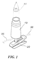
- FIG. 1 An incandescent lamp holder 10 with a clamp connection is shown in FIG. 1 as an example.
- the upper part of the bulb holder 10 with a clamp connection can be connected to a Light bulb 11 are connected while the bottom of the same with a clamp 20th can be connected; electrical conductors 95, 96 can be from the bottom of the Incandescent lamp holder 10 can be pulled into its interior.
- the bulb socket 10 has the present one Invention generally a hollow cone shape; the upper end of it is an upper one Cover 14, which fits the light bulb 11.
- the hollow interior of the Incandescent lamp holder 10 can be connected to a connecting device 30 and water-retaining washer 90, which is located under the connecting device 30 located.
- the connecting device 30 is in cooperation with the hollow, conical Incandescent lamp holder 10 with an annular base 31 with a suitable Diameter.
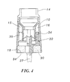
- the annular base 31 has two on its opposite lying sides two chamfered notches 32, 33 and it has on its upper Surface of two insertion columns 34, 35 for insertion into corresponding inner chambers 15, 16 of the bulb holder 10 (see Fig. 4).
- One serving as a fulcrum Connecting axis 37 with a ball end 36 extends away from the floor.
- the Ball end 36 is inserted through the clamp 20 in the manner of a Universal joint connected (see Fig. 3).
- the clamp 20 comprises an upper plate 21, a lower clamping plate 22 and a built-in spring element 23.
- the spring element 23 has elastic bending ends 24, 25, which are each arranged in the holes, which are located on the upper and lower clamping plate 21, 22.
- One of the bending ends has an extension 26 (with a hole 261), which extends into a recess 27 especially to position the ball end 36 in a cooperative manner.
- the water-retaining disc 90 is made of elastomer, which is in the form of a has annular ring and to the inner environment of the bulb holder 10th fits, and whose thickness is slightly less than the height H in the bottom of the Incandescent lamp holder 10.
- the water-retaining disc 90 has a central hole 91 equipped, which is able to provide a tight connection to the pivot point serving connecting axis 37, and it has two side holes 92, 93 equipped with the above-mentioned two chamfered notches 32, 33 communicate.
- the outer circumference of the water-retaining disc 90 is one annular recess 94 which is capable of resiliently in to engage the annular flange 18.
- the connecting device 30 extends in FIG Incandescent lamp holder 10 with its connecting axis 37 serving as a fulcrum the central hole 91 and is connected to the clamp 20 by means of its ball end 36.
- the two side electrical conductors 95, 96 can pass through the two side holes 92, 93 of the water-retaining disc 90 and then drawn in an oblique manner be pulled up so that their core lines 951, 961 with the one above Light bulb 11 can be connected.
- the water-retaining washer 90 itself is made of elastomer, the insulating cover of the side electrical conductors 95, 96 and the connection axis 37 serving as the fulcrum can obtain the desired seal, and the whole bulb socket 10 with the annular flange 18 is in elastic engagement with the annular recess 94 on the water-holding disc 90 under the connecting device 30.
- This achieves a very effective and well-watertight mechanism and improves tear resistance, the bulb socket and the clamping connection device 30 contained therein can be a better and more reliable at their connection point Preserved waterproof function.
- the present invention provides a watertight structure of a clip-type light bulb holder capable of improving the waterproof function of such a type of light bulb holder, the light bulb holder being particularly suitable for outdoor use.
- the entire room layout is new and includes practical improvements.
Landscapes
- Engineering & Computer Science (AREA)
- General Engineering & Computer Science (AREA)
- Fastening Of Light Sources Or Lamp Holders (AREA)
- Arrangement Of Elements, Cooling, Sealing, Or The Like Of Lighting Devices (AREA)
- Connecting Device With Holders (AREA)
Abstract
Description
- Fig. 1
- eine Perspektivansicht, welche eine Ausführungsform der vorliegenden Erfindung zeigt;
- Fig. 2
- eine analytische Ansicht, welche die Elemente von Fig. 1 zeigt:
- Fig. 3
- eine Schnittansicht von Fig. 1;
- Fig. 4
- ebenfalls eine Schnittansicht von Fig. 1, doch in einem Winkel von 90 Grad betrachtet;
- Fig. 5
- eine schematische Ansicht ähnlich jener von Fig. 3, welche die Verlegung der elektrischen Leiter zeigt;
- Fig. 6
- eine Schnittansicht entlang der Linie 6-6 von Fig. 5;
- Fig. 7
- eine Schnittansicht entlang der Linie 7-7 von Fig. 5;
Zusammenfassend kann gesagt werden, dass die vorliegende Erfindung eine wasserdichte Struktur einer Glühlampenfassung mit Klemmanschluss schafft, die in der Lage ist, die wasserdichte Funktion einer solchen Art von Glühlampenfassungen zu verbessern, wobei sich die Glühlampenfassung besonders für die Verwendung im Freien eignet. Die gesamte Raumanordnung ist neuartig und umfasst praktische Verbesserungen.
Claims (5)
- Wasserdichte Struktur einer Glühlampenfassung mit Klemmanschluß, wobei das obere Ende der Glühlampenfassung mit Klemmanschluß mit einer Glühbirne verbunden ist, während ihr unterer Teil mit einer Klemme verbunden ist, wobei das hohle Innere der Glühlampenfassung mit einer Verbindungsvorrichtung verbunden ist,
dadurch gekennzeichnet, daß
die Verbindungsvorrichtung mit einem ringförmigen Sockel ausgestattet ist, an deren oberer Oberfläche zwei Einfügesäulen zur Verbindung durch Einfügung in entsprechende Innenkammern der Glühlampenfassung vorhanden sind, sich eine als Drehpunkt dienende Verbindungsachse vom Boden der Verbindungsvorrichtung weg erstreckt, um sich mit der Klemme zu verbinden, daß ein Aufnahmeraum mit einer eingestellten Höhe zwischen dem ringförmigen Sockel und der unteren Oberfläche der Glühlampenfassung nach dem Verbinden frei bleibt, und daß eine wasseraufhaltende Scheibe ein mittiges Loch und zwei seitliche Löcher umfasst, durch welche die als Drehpunkt dienende Verbindungsachse der Verbindungsvorrichtung und die elektrischen Leiter geführt sind und der Aufnahmeraum dadurch gut abgedichtet ist. - Wasserdichte Struktur einer Glühlampenfassung mit Klemmanschluß nach Anspruch 1,
dadurch gekennzeichnet, daß
die Glühlampenfassung mit dem darin vorhandenen Aufnahmeraum mit einem ringförmigen Flansch ausgestattet ist, der zum Zwecke der Positionierung in eine ringförmige Aussparung am ringförmigen Sockel eingreift. - Wasserdichte Struktur einer Glühlampenfassung mit Klemmanschluss nach Anspruch 1,
dadurch gekennzeichnet, daß
der ringförmige Sockel der Verbindungsvorrichtung an zwei gegenüberliegenden Seiten zwei abgeschrägte Kerben aufweist, um die elektrischen Leiter dort hindurch nach oben zu führen zur Verbindung mit einer Glühbirne. - Wasserdichte Struktur einer Glühlampenfassung mit Klemmanschluß nach Anspruch 1,
dadurch gekennzeichnet, daß
die als Drehpunkt dienende Verbindungsachse am Boden der Verbindungsvorrichtung eine Kugelendeinführung aufweist, die mit der Klemme in der Art eines Universalgelenks verbunden ist, indem sie sich durch ein oberes Blech und ein unteres Klemmblech der Klemme erstreckt. - Wasserdichte Struktur einer Glühlampenfassung mit Klemmanschluß nach Anspruch 4,
dadurch gekennzeichnet, daß
die Klemme ein oberes Blech und ein unteres Klemmblech umfasst, wobei ein Federelement darin vorhanden ist, und dass sie eine Verlängerung mit einem Loch besitzt und verlängert wird, um auf kooperative Weise das Kugelende zu positionieren.
Applications Claiming Priority (2)
| Application Number | Priority Date | Filing Date | Title |
|---|---|---|---|
| DE29920886U | 1999-11-26 | ||
| DE29920886U DE29920886U1 (de) | 1999-11-26 | 1999-11-26 | Wasserdichte Struktur einer Glühlampenfassung mit Klemmanschluß |
Publications (2)
| Publication Number | Publication Date |
|---|---|
| EP1103760A2 true EP1103760A2 (de) | 2001-05-30 |
| EP1103760A3 EP1103760A3 (de) | 2004-01-14 |
Family
ID=8082200
Family Applications (1)
| Application Number | Title | Priority Date | Filing Date |
|---|---|---|---|
| EP00121181A Withdrawn EP1103760A3 (de) | 1999-11-26 | 2000-09-29 | Wasserdichte Struktur einer Glühlampenfassung mit Klemmanschluss |
Country Status (2)
| Country | Link |
|---|---|
| EP (1) | EP1103760A3 (de) |
| DE (1) | DE29920886U1 (de) |
Family Cites Families (4)
| Publication number | Priority date | Publication date | Assignee | Title |
|---|---|---|---|---|
| US4935852A (en) * | 1989-03-30 | 1990-06-19 | Aidy Hsu | Decorative bulbholder |
| DE4203421A1 (de) * | 1992-02-06 | 1993-08-12 | Heinrich Korte | Halterung fuer eine gluehbirne |
| EP0829676A1 (de) * | 1996-09-13 | 1998-03-18 | Calvin Chun Yin Lau | Glühbirne und Beleuchtungssystem für Dekorationszwecke mit einer solchen |
| GB2322185A (en) * | 1997-02-15 | 1998-08-19 | Raymond Walter Harcombe | Battery powered Christmas tree decoration shaped like a candle |
-
1999
- 1999-11-26 DE DE29920886U patent/DE29920886U1/de not_active Expired - Lifetime
-
2000
- 2000-09-29 EP EP00121181A patent/EP1103760A3/de not_active Withdrawn
Non-Patent Citations (1)
| Title |
|---|
| None |
Also Published As
| Publication number | Publication date |
|---|---|
| EP1103760A3 (de) | 2004-01-14 |
| DE29920886U1 (de) | 2000-01-27 |
Similar Documents
| Publication | Publication Date | Title |
|---|---|---|
| DE20017947U1 (de) | Satz aus Zierglühbirne und Sockeladapter | |
| DE19705798C2 (de) | Mit geringer Kraft kuppel- und entkuppelbarer Steckverbinder | |
| DE19800099C2 (de) | Verfahren zur Herstellung eines Leitungsverbinders | |
| DE10259767A1 (de) | Drahthaltekonstruktion für einen Sammelverbinder und damit ausgestatteter Sammelverbinder | |
| DE2210904B2 (de) | Elektrische Steckbuchse | |
| DE1962231B2 (de) | Elektrisches Kontaktelement | |
| EP1155475B1 (de) | Elektrischer steckverbinder | |
| DE3938931A1 (de) | Wasserdichter schlitzkontaktverbinder | |
| DE2819350A1 (de) | Lampenfassung | |
| WO1981001082A1 (fr) | Dispositif de couplage electrique | |
| DE102004056945A1 (de) | Hebelverschluss-Steckerverbindung | |
| DE10024029A1 (de) | Elektrische Steckverbindung | |
| DE29708604U1 (de) | Weihnachtslampensockel | |
| DE19811667C2 (de) | Kabelsteckverbinder | |
| DE29710298U1 (de) | Antrieb für Verstelleinrichtung, insbesondere an Sitz- und Liegemöbeln | |
| DE3720751A1 (de) | Elektrische verbinderanordnung | |
| DE2106178B2 (de) | Elektrischer Kontakt | |
| DE20308104U1 (de) | Lampenfassung für Leuchtstoffröhren | |
| DE29920886U1 (de) | Wasserdichte Struktur einer Glühlampenfassung mit Klemmanschluß | |
| EP1280236B1 (de) | Anordnung zum Anschliessen eines elektrischen Verbrauchers an eine Versorgungsleitung | |
| EP1467448B1 (de) | Steckeradapter, insbesondere zum Anschluss von Lampen | |
| DE202019100975U1 (de) | Wasserdichte Verbindungsvorrichtung für LED-Lichtleisten | |
| DE202005017981U1 (de) | Kontakthalterung für elektrische Steckverbinder | |
| DE4102681C2 (de) | Grundkörper für Steckdosen und Stecker | |
| DE128349C (de) |
Legal Events
| Date | Code | Title | Description |
|---|---|---|---|
| PUAI | Public reference made under article 153(3) epc to a published international application that has entered the european phase |
Free format text: ORIGINAL CODE: 0009012 |
|
| AK | Designated contracting states |
Kind code of ref document: A2 Designated state(s): AT BE CH CY DE DK ES FI FR GB GR IE IT LI LU MC NL PT SE |
|
| AX | Request for extension of the european patent |
Free format text: AL;LT;LV;MK;RO;SI |
|
| PUAL | Search report despatched |
Free format text: ORIGINAL CODE: 0009013 |
|
| AK | Designated contracting states |
Kind code of ref document: A3 Designated state(s): AT BE CH CY DE DK ES FI FR GB GR IE IT LI LU MC NL PT SE |
|
| AX | Request for extension of the european patent |
Extension state: AL LT LV MK RO SI |
|
| RIC1 | Information provided on ipc code assigned before grant |
Ipc: 7H 01R 33/965 B Ipc: 7F 21V 31/00 B Ipc: 7F 21V 19/00 A |
|
| AKX | Designation fees paid |
Designated state(s): AT BE CH CY DE DK ES FI FR GB GR IE IT LI LU MC NL PT SE |
|
| STAA | Information on the status of an ep patent application or granted ep patent |
Free format text: STATUS: THE APPLICATION IS DEEMED TO BE WITHDRAWN |
|
| 18D | Application deemed to be withdrawn |
Effective date: 20040715 |