EP1103640A1 - Selektive Reinigungslinie - Google Patents
Selektive Reinigungslinie Download PDFInfo
- Publication number
- EP1103640A1 EP1103640A1 EP00811064A EP00811064A EP1103640A1 EP 1103640 A1 EP1103640 A1 EP 1103640A1 EP 00811064 A EP00811064 A EP 00811064A EP 00811064 A EP00811064 A EP 00811064A EP 1103640 A1 EP1103640 A1 EP 1103640A1
- Authority
- EP
- European Patent Office
- Prior art keywords
- processing
- flake
- transport
- fiber
- cleaning
- Prior art date
- Legal status (The legal status is an assumption and is not a legal conclusion. Google has not performed a legal analysis and makes no representation as to the accuracy of the status listed.)
- Granted
Links
Images


Classifications
-
- D—TEXTILES; PAPER
- D01—NATURAL OR MAN-MADE THREADS OR FIBRES; SPINNING
- D01G—PRELIMINARY TREATMENT OF FIBRES, e.g. FOR SPINNING
- D01G13/00—Mixing, e.g. blending, fibres; Mixing non-fibrous materials with fibres
-
- D—TEXTILES; PAPER
- D01—NATURAL OR MAN-MADE THREADS OR FIBRES; SPINNING
- D01G—PRELIMINARY TREATMENT OF FIBRES, e.g. FOR SPINNING
- D01G31/00—Warning or safety devices, e.g. automatic fault detectors, stop motions
- D01G31/003—Detection and removal of impurities
Definitions
- blowroom also includes the card, which fiber material from the traditional cleaning machines of the blow room for further processing.
- Blowrooms are therefore designed to use different types of materials (Assortments) to edit, whereby the end user of an assortment switch to another or even different assortments quasi-simultaneously (“Multi-range operation”) can process.
- Blowroom lines also include a number of machines that process the fiber material of the Preserved and processed in sequence.
- the different operating parameters e.g. how flow rate of the fiber material and aggressiveness of fiber processing
- the achievable Properties of the supplied fiber material usually in the form of flakes from the cleaning machines or sliver - or at most a nonwoven the teasel.
- These complex interactions have led to proposals that aim to simplify the setting of the individual machines. This will for example in EP-A-399,315 or EP-A-641,876, GB-A-2210907 and EP-A-452,676 described.
- GB-A-2210907 describes a device the optimization of the cleaning or operating parameters of the following fiber processing machine serves.
- test devices are particularly relevant with regard to their sensors have been further developed - examples of newer devices using optical sensors work are described in EP-A-396,546; EP-A-824,607 and DE-A-4340173. It is to expect further developments of the (optical) sensors.
- the invention accordingly provides a flake transport device with a switching means for the flocculation before, with a test device which determines the degree of contamination checks the fiber material, the testing device carrying out an evaluation, which determines the cleaning needs of the tested material and the switching means controls accordingly.
- the invention further comprises a fiber processing method which has several Transport routes with different processing characteristics required.
- the fibers are allocated to the transport routes via a common feed, whereby in the common Feed the condition of the fibers is checked. After that, the fibers are in Depends on the results of the test in one way or another forwarded.
- the invention also includes a fiber processing plant with several transport routes, which have different machining characteristics, and with a common fiber supply for the transport routes mentioned.
- a test device is provided to check the condition of the fiber supplied by the feed.
- the attachment also includes a controllable switching means depending on the flocculation to switch from the test results to the different transport routes.
- a transport route is understood to mean the route which is a single fiber flake from the bale opener to the end product (e.g. in the sliver after the card) can go through.
- a switching means or a switching device U ends in two or three branches, there are just as many new ones Transport routes.
- a transport route is actually characterized by its sections. Each section contains one or more processing stages (one processing stage is defined according to the technology and can consist of one or more Machines exist, e.g. the fine cleaning).
- the switching means or switching devices U are switched, the flakes flow through different sections and therefore a transport route with a processing characteristic which is characterized by its subsections.
- a section can be divided into several Transport routes belong.
- the end products of the individual transport routes processed separately. It is according to one second embodiment of the invention, however, provided that the end products are individual Transport routes, which have different properties, partly or can be mixed again completely (e.g. end product of a transport route with lower quality is mixed with several high quality end products.) At only partial mixture, several end products are obtained almost simultaneously in this way (or "product lines") with different fiber properties.
- This is kind of a multi-range company.
- a second type of such a multi-range company can be implemented with a central control device and is explained in the following section.
- Another embodiment of the invention provides for the different transport routes a central control means with different processing characteristics in front.
- This control means can, in addition to the test devices, the individual switching means and control the switching devices U. It is also conceivable that Control means centrally processes and / or registers the evaluations of the test devices.
- the preferred properties of such a fiber processing plant include that you can partially specify the transport routes. This allows several "Product lines" are formed with different compositions (respectively Qualities) in the end products. For example, it is conceivable that one a bale template with several assortments (that is, different fiber bales Origin and quality with different fiber properties, such as pile length, degree of contamination etc.) has.
- the bale opener for example the A11 from Rieter, carries then the flakes of the different bales in turn.
- One plant, the bale of different origins and thereby the operating parameters of the following processing stages The assortment of the bale just removed has been around since EP-A-399,315 known.
- an end product with is known from this document to get a composition. It would be with the system according to the invention thanks to the central control unit, a bale feed with several ranges is possible to have, but the fiber material flow of the individual bales through the transport routes to control up to the end product (multi-range operation). That way you have several "product lines" on a single system and produce almost simultaneously several end products of different, homogeneous composition.
- the transported flakes also meet the determined cleaning need processed accordingly.
- the composition of the different ranges in the end products of each "product line" can be done by the central control unit can be predetermined (but end products with fibers of one are also conceivable Assortment).
- the central control unit can also optimizes the transport route according to the amount of fiber just delivered. This is particularly advantageous when certain transport lines can only process limited throughputs of fibers.
- the individual sections can also contain buffers to compensate for natural irregularities in the fiber feed.
- the buffers can also be designed as filling chutes for the following processing stage.
- a flock transport device for textile processing machines with a switchover means for the flock flow which contains a test device or several test devices which measure the degree of soiling of the fiber material being transported, the test device or another device (e.g. the switchover device connected downstream, a control means) in each case carrying out an evaluation , which determines the cleaning need of the tested material and controls at least one switching means accordingly.
- the invention also includes flock transport devices with one or more so-called bypass units, which are connected both in series and in parallel can be.
- a bypass unit has a common flake feed, which is divided into two or more separate transport routes, the first transport route without processing level and all other transport routes with one processing level are equipped.
- At the end of the bypass unit are the transport routes merged again so that the transport routes of the bypass unit come together again have a common output, or each bypass unit has only one output Has.
- the bypass unit according to the invention can be designed such that each unit on the common flake feed a test device and a downstream one Has switching element, wherein the tester performs an evaluation, which the The need for cleaning of the transported fiber material is determined and accordingly downstream switching means which controls the evaluated fiber material either in a transport route with a suitable processing stage or in the Transport route leads without processing stage.
- the transport routes at the end of the bypass unit are by definition brought together again so that there is only one Output of the bypass unit results.
- one according to the invention is also included Flake processing method for textile processing machines.
- the procedure is characterized in that several transport routes with different processing characteristics it is intended that the flakes have a common one Flakes are fed through a transport route, being in the common Flake feed the condition of the flakes is checked, and that depending on the Results of this test passed the flakes in one way or another become.
- a transport route cannot include a processing stage included (bypass system).
- the flake processing method mentioned in the last paragraph also includes bypass units according to the invention. That means having multiple transport routes Different processing characteristics are provided that the flakes can be fed via a common flake feed through a transport route, the condition of the flakes is checked in the common flake feed, and that depending on the results of this test, the flakes in one or other transport route and the transport routes at their end be brought together again.
- test devices For flake processing system for textile processing machines with several Transport routes with different processing characteristics, with a common one Flake feed (for example from the bale opener) for the transport routes mentioned,
- Flake feed for example from the bale opener
- one or more test devices also belong. These test devices measure and check the condition of the flakes just transported.
- controllable switching means are provided, which depend on the flocculation from the test results, i.e. Condition of the fiber flakes, for the appropriate one Switch the transport route.
- the test device is the Carry out an evaluation and when a certain threshold value (certain Degree of contamination of the fiber flakes) the signal for switching to the switching means give.
- a certain threshold value certain Degree of contamination of the fiber flakes
- This has the advantage that you also have a central one Can provide tax funds. This could register the measured values and others Make evaluations, for example the optimal operating parameters of the concrete Transport route section determine the following processing stages and this Send parameters online to the corresponding machines or send them accordingly Taxes.
- the invention is not limited to this possibility.
- test device only carries out the test or measurement and continuously sends a signal to the switching means. Only when this signal reaches a certain threshold - specified in the switching means - it switches around. It is also possible for the test device to carry out the evaluations or only the Takes measurements continuously and sends them to the central control means which then decides or first evaluates the measured values and then decides whether the switching means is to be activated or not (possibly depending on other factors).
- a flake processing plant according to the invention can for textile processing machines also transport routes with one or more Bypass units include. If there are several bypass units, these can be used one after the other, that is in series, and / or side by side, that is in parallel, be arranged.
- the inventive concept further includes that for the flake processing plant belonging transport routes each contain one or more processing stages can.
- the transport routes consist of no less than a section. Each section can, but does not have to, one or more processing stages contain.
- the results determined by the test devices on the condition the flakes also for setting the operating parameters of the following processing stage or processing stages can serve.
- the Measurements of the test devices by the test devices themselves, by the central control means, or by another evaluation device connected to the following processing stages be evaluated.
- the invention includes the use of the required test devices in the inventive Flake transport devices and flake processing plants. These can the degree of cracking of the fiber flakes and / or the degree of contamination of the fiber flakes measure and / or measure the degree of opening of the fiber flakes.
- the test equipment can preferably also evaluate the measured values themselves.
- the invention also includes the use of one or more suitable switching means for the flake transport devices and flake processing plants according to the invention.
- switching means are actually from the prior art known. Their use in a device according to the invention is new and inventive or plant.
- the actual switching means can be a device, for example be one that releases one or more gas impluses around the fiber material in question redirect (e.g. into another transport route).
- Such devices are the documents already mentioned, in particular EP-A-396 546, DE-A-43 40 173 and EP-A-824 607.
- Another type of switching means that can be used is in US 4,171,262: There the device consists of a pneumatically movable Flap and an associated control. Of course that has to be Switching means that can be used according to the invention do not apply to these two types of device restrict.
- the inventive concept further includes the idea that one or more test devices for use in flake transport devices and flake processing plants as described above in combination with at least one Switching means should be used.
- test devices with other measuring devices, how to couple a foreign fiber separation device so that these together can interact.
- the flake processing plant for textile processing machines preferably a central control means for controlling contains the amount of flakes and assortments fed in by the food.
- the switching device or devices U and the switching device or devices of the flake processing system are additionally connected to the control means and the control means can also control or determine the transport routes depending on the assortment currently supplied by the food (e.g. the bale opener A11), and / or the amount of fiber supplied and / or the desired final composition of the Product (or end product of the line such as sliver, wadding, fleece, etc.).
- the Control means can be set (or programmed) so that it itself is the optimal or necessary transport routes for the flakes depending on the above Factors determined.
- control means cannot control the transport routes arbitrarily, but rather is bound to certain framework conditions (especially the condition that a optimal cleaning should be achieved or that for example certain transport routes are intended for other ranges and cannot be selected).
- the invention includes the use of one or more of the following processing stages in the flake processing plants according to the invention: the Rough cleaning, fine cleaning, intensive cleaning, intensive opening or Mixture or a combination of the processing types mentioned.
- the results of the test equipment on the state of the transported Fiber flakes not only serve to switch the optimal transport route, but also that this evaluation also for setting certain operating parameters of the following Processing stage can serve.
- the upstream test device can do this directly interact with the following processing stage, as well as via a central control means, which registers the evaluation of the test device, the necessary operating parameters determined and this passes on to the following processing stage.
- the processing characteristics of the different transport routes differ preferably regarding the intensity (e.g. aggressiveness) in fiber processing. Thereby create e.g. different cleaning effects or different opening effects.
- a relatively dirty, or containing nits, or poorly opened Accordingly, material is redirected into a transport route, the machines and devices has a relatively high cleaning and opening effect (but with relative high fiber stress, e.g. Stack reduction).
- a relatively pure material is in a transport route with a relatively fiber-friendly processing characteristics (no cleaning machines at all), taking into account that the existing level of pollution is hardly reduced.
- the blowroom line according to FIG. 1 comprises a bale opener A11, a coarse cleaner B11, optionally a foreign fiber test or separation device VS, two "UNlmix” mixing machines, and two B60 fine cleaners, which also serve as card feeding machines.
- the following cards can be of conventional construction, but are no longer shown.
- the A11 bale opener is suitable for fiber material in the form of flakes to deliver with a production of approx. 1200 kg / h (per hour).
- the flake stream will then between the machines of the line in a pneumatic transport system (indicated schematically by connecting lines), the whole (undivided) Current can flow through the coarse cleaner B11 and the test device VS.
- the other machines in the line are only suitable for a flocculation with one Process flow of maximum 600 kg / h.
- the delivered flake stream is therefore after the test device VS in two partial flows (each divided into a partial line A or B). This is done by means of a switching device U.
- the test device itself plays in this Connection does not matter.
- the device can e.g. to be built according to EP-A-824 607 and serves to remove foreign material from the flake stream e.g. via a branch L to be eliminated.
- the processing characteristics of the two sub-lines A and B can be the same (only one assortment) or different (multi-assortment operation).
- the steering of the device U takes place either in dependence on the fill levels of memories the sub-lines A or B (only one assortment) or depending on switching signals from the A11 bale opener (multi-range operation).
- the blow room according to FIG. 2 essentially comprises the same opening cleaning and. Mixer types that are not described individually again.
- the arrangement of these machines is now different and the test device PF differentiates the device VS according to FIG. 1, as will be explained in more detail below.
- the Flock flow supplied by bale opener A11 is now fed directly to the device PF and the transport system after the device PF is divided into three sub-lines X, Y, Z.
- the the two sub-lines X and Y branch off from a switching device U (cf. FIG. 1) and they each have only one UNlmix mixer for fiber processing.
- the third part line Z includes a coarse cleaner B11, mixing machine UNlmix and a fine cleaner B60.
- This part line branches off from the test device PF, i.e. the latter device includes in this Variant of a controllable switching device (see after, Fig. 4), which flowing material switches between an output I and an output II.
- Output I leads to the switching device U, while output II leads to the
- the device PF uses its sensors (with a corresponding signal evaluation) determines whether the material supplied by the bale opener fulfills predetermined criteria. Examples of such criteria have been mentioned in the introduction to the description. These can be used individually or in combination in the control to achieve this Initiate switching between outputs I and II. Relatively dirty or containing nits Material is diverted to exit II (in line Z), while pure Material is passed through to the exit I.
- the partial lines can be designed in this way that the two lines X and Y e.g. a throughput or production of 450 kg / h, whereas the Z part line only has a throughput or production of approx. Has 300 kg / h.
- the product of the sub-line X or Y can be used to manufacture higher yarns Qualities, the Z line product is used to produce lower quality yarns become.
- the variant according to FIG. 3 will be clear without a longer description - it corresponds the variant according to Figure 2, with the exception that the coarse cleaner B11 has again been placed in front of the test device PF (cf. FIG. 1).
- the whole production of the Bale opener A11 is thus a rough cleaning step, with relatively low work intensity, subject, only the dirty part of the intensive fine cleaning is subjected.
- the test device PF comprises a flow channel K for the flake flow (schematically indicated with FS), the two outputs I and II and one controllable diverter flap V.
- Light sources Q are on one side of the channel K, Photosensors F on the opposite side.
- the channel walls are translucent here.
- the signals from the sensors F are delivered to an evaluation W, where they are evaluated according to the aforementioned criteria.
- flap V using suitable actuators switched to open output I or output II.
- Changeover flap V shown can also be used as switching means other elements / principles are used, for example by means of pneumatic blowing or suction the fiber flakes. This can be both general, i.e.
- Such switching means are, for example already from US 4,171,262, DE-A-43 40 173, DE-A-197 22 537, EP-A-396,546, or EP-A-824 607.
- the invention is not restricted to the examples shown. These variants can e.g. further developed based on the principles listed in EP-A-810 309 with a fine cleaning step in the carding machine. Such a further development could e.g. to supplement the cleaning effect in a partial line X and / or Y or to replace the fine cleaner B60 in the Z part line.
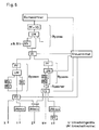
- a bypass unit is shown in FIG. As you can see in the picture a memory can be provided at the input of the unit. The flake feed leads then past a test device. For the sake of simplicity, this document often uses talked to a tester. However, this does not exclude that "a test device" in but itself consists of several such devices or sensors, so that too several flake properties can be measured simultaneously. From a technical point of view connects a switching device to the testing device. As indicated in Figure 4 is, the switching means can also be in the same housing. The Switching means has two outputs in the illustration. At the first exit the pass where there is no fiber processing. The second exit leads to a processing level. They are also bypass units with more than two outlets conceivable from the switching device and several processing stages. At the end of the bypass unit lead the sections with the different processing stages back together and thus form an output from the bypass unit.
- FIG. 6 shows an example of a flake processing plant. It contains a combination of different flake transport devices and several transport routes that lead to different products.
- the bale opener which can have a bale template with different assortments, is connected here, for example, to a central control means. This control means can interact with the bale opener. Depending on the assortment just removed, the control means can control the transport routes within certain limits.
- the pneumatic transport system leads the flake flow from the bale opener to the first bypass unit.
- the test device PF interacts with a further detector VS (for example a metal detector).
- the UM switching device connected downstream also has a possibility of separating foreign substances.
- the processing stage BS of this unit can represent, for example, a coarse cleaner, such as the B11 from Rieter.
- This flock transport device is followed by a changeover device U 1 , which is only controlled by the central control means (generally as a function of the range that has just been removed).
- the switching device U 1 divides the transport system into two partial flows.
- Another bypass with three different sections and another switchover device U 2 which is likewise controlled by the central control means, follows in the left partial flow.
- the end products X, Y or Z are obtained. It should be noted that each of these end products can pass through different transport routes. These transport routes are also not fully controllable by the control means because not all of the switchover means UM can be controlled.
- In the right-hand partial flow after the switching device U 1 there is a further bypass with a different flock flow within the same bypass unit.
- the switching device UM is connected to the control device.
- the output of the bypass leads the flake flow to a store.
- the following switching device U 3 (also connected to the control means) has three outputs which lead to three end products, one product being mixed with the fiber stream from the left-hand partial stream. Individual outputs of U 2 and U 1 are followed by further processing stages, such as mixing in the Unimix machines. The following processing of the fibers in such a system (eg carding) is no longer shown.
Landscapes
- Engineering & Computer Science (AREA)
- Textile Engineering (AREA)
- Preliminary Treatment Of Fibers (AREA)
Abstract
Description
Wo es angebracht ist, können die einzelnen Teilabschnitte auch Zwischenspeicher enthalten, um naturgegebene Ungleichmässigkeiten in der Faserbeschickung auszugleichen. Bevorzugterweise können die Zwischenspeicher auch gleichzeitig als Füllschächte für die folgende Bearbeitungsstufe ausgebildet sein.
Eine Flockentransportvorrichtung für Textilverarbeitungsmaschinen mit einem Umschaltmittel für den Flockenstrom, die ein Prüfgerät oder mehrere Prüfgeräte enthält, welches bzw. welche den Verschmutzungsgrad des transportierten Fasermaterials messen, wobei das Prüfgerät oder ein weiteres Gerät (z.B. das nachgeschaltete Umschaltmittel, ein Steuermittel) jeweils eine Auswertung vornimmt, welche das Reinigungsbedürfnis des geprüften Materials ermittelt und wenigstens ein Umschaltmittel entsprechend steuert.
- Anzahl der enthaltenen Schmutzteilchen:
Die von den Sensoren gelieferten Signale können in einer Auswertung gezählt werden und vorzugsweise auch nach Grösse bzw. nach der Häufigkeit verschiedener Grössen untersucht werden. Für jedes ausgewählte Kriterium kann mindestens ein Schwellwert festgesetzt werden, so dass beim Überschreiten des Schwellwertes das Umschalten eingeleitet wird. - Anzahl der enthaltenen Faserverknotungen/"Nissennester":
Auch hier kann nach der Häufigkeit untersucht werden bzw. es kann die Häufigkeit als Umschaltkriterium in der Steuerung definiert werden. - Momentane Flockengrösse
- Farbton des Materials
- Fig. 1
- einen Plan einer konventionellen Putzerei zum Vergleich;
- Fig. 2
- einen Plan einer ersten Ausführung einer Putzereilinie gemäss der Erfindung;
- Fig. 3
- einen Plan einer zweiten Ausführung einer erfindungsgemässen Putzereilinie,
- Fig. 4
- einen Querschnitt durch ein Prüfgerät mit einem Umschaltmittel gemäss der Erfindung,
- Fig. 5
- eine Bypass-Einheit, und
- Fig. 6
- ein Beispiel einer möglichen Flockenverarbeitungsanlage mit verschiedenen Flockentransportvorrichtungen und mehreren Transportwegen.
Claims (16)
- Eine Flockentransportvorrichtung für Textilverarbeitungsmaschinen mit einem Umschaltmittel für den Flockenstrom, dadurch gekennzeichnet, dass sie ein Prüfgerät oder mehrere Prüfgeräte enthält, welches bzw. welche den Verschmutzungsgrad des transportierten Fasermaterials messen, wobei jeweils eine Auswertung vorgenommen wird, welche das Reinigungsbedürfnis des geprüften Materials ermittelt und wenigstens ein Umschaltmittel entsprechend steuert.
- Flockentransportvorrichtung nach Anspruch 1 dadurch gekennzeichnet, dass die Flockentransportvorrichtung eine oder mehrere, in Serie oder parallel geschaltete, Bypass-Einheiten beinhaltet, welche sich jeweils von einer Flockenzufuhr in zwei oder mehrere getrennte Transportwege aufteilen, wobei der erste Transportweg ohne Bearbeitungsstufe und alle weiteren Transportwege mit einer Bearbeitungstufe ausgestattet sind, und am Ende der Bypass-Einheit die Transportwege wieder einen gemeinsamen Ausgang haben.
- Bypass-Einheit nach Anspruch 2, dadurch gekennzeichnet, dass jede Einheit an der Flockenzufuhr ein Prüfgerät und ein diesem nachgeschaltetes Umschaltelement besitzt, wobei das Prüfgerät eine Auswertung vornimmt, welche das Reinigungsbedürfnis des transportierten Fasermaterials ermittelt und entsprechend das nachgeschaltene Umschaltmittel steuert, welches das ausgewertete Fasermaterial entweder in einen Transportweg mit einer geeigneten Bearbeitungsstufe oder in den Transportweg ohne Bearbeitungstufe führt, wobei die Transportwege am Ende der Bypass-Einheit wieder zusammengeführt werden und so einen einzigen Ausgang der Bypass-Einheit bilden.
- Ein Flockenverarbeitungsverfahren für Textilverarbeitungsmaschinen, dadurch gekennzeichnet, dass mehrere Transportwege mit unterschiedlichen Bearbeitungscharakteristiken vorgesehen sind, dass die Flocken über eine gemeinsame Flockenzufuhr durch einen Transportweg zugeführt werden, wobei in der gemeinsamen Flokkenzufuhr den Zustand der Flocken geprüft wird, und dass in Abhängigkeit von den Ergebnissen dieser Prüfung die Flocken in den einen oder anderen Transportweg weitergeleitet werden, wobei ein Transportweg davon auch keine Bearbeitungsstufe enthalten kann.
- Ein Flockenverarbeitungsverfahren für Textilverarbeitungsmaschinen nach Anspruch 4, dadurch gekennzeichnet, dass die Transportwege an ihrem Ende wieder zusammenführen.
- Eine Flockenverarbeitungsanlage für Textilverarbeitungsmaschinen mit mehreren Transportwegen mit unterschiedlichen Bearbeitungscharakteristiken, mit einer gemeinsamen Flockenzufuhr für die genannten Transportwege, und mit einem oder mehreren Prüfgeräten, welche den Zustand der transportierten Flocken prüfen, wobei ein oder mehrere steuerbare Umschaltmittel vorgesehen sind, um den Flockenstrom in Abhängigkeit von den Prüfergebnissen zum geeigneten Transportweg zu schalten.
- Eine Flockenverarbeitungsanlage für Textilverarbeitungsmaschinen nach Anspruch 6, dadurch gekennzeichnet, dass die Transportwege einen oder mehrere Bypass-Einheiten beinhalten.
- Eine Flockenverarbeitungsanlage für Textilverarbeitungsmaschinen nach Anspruch 6, dadurch gekennzeichnet, dass die Transportwege jeweils eine oder mehrere Bearbeitungstufen enthalten.
- Eine Flockenverarbeitungsanlage für Textilverarbeitungsmaschinen nach Anspruch 6, dadurch gekennzeichnet, dass die von den Prüfgeräten ermittelten Ergebnisse zum Zustand der Flocken auch zur Einstellung der Betriebsparameter der folgenden Bearbeitungsstufe oder Bearbeitungsstufen dienen.
- Prüfgeräte für die Verwendung in Flockentransportvorrichtungen und Flockenverarbeitungsanlagen gemäss den vorangehenden Ansprüchen, dadurch gekennzeichnet, dass die Prüfgeräte den Vernissungsgrad der Faserflocken und/oder den Verschmutzungsgrad der Faserflocken messen und/oder den Öffnungsgrad der Faserflocken messen und bevorzugterweise auch auswerten.
- Umschaltmittel für die Verwendung in Flockentransportvorrichtungen und Flockenverarbeitungsanlagen gemäss den vorangehenden Ansprüchen.
- Prüfgeräte für die Verwendung in Flockentransportvorrichtungen und Flockenverarbeitungsanlagen gemäss den vorangehenden Ansprüchen, dadurch gekennzeichnet, dass das oder die Prüfgeräte in Kombination mit mindestens einem Umschaltmittel verwendet wird/werden.
- Flockentransportvorrichtungen und Flockenverarbeitungsanlagen gemäss den vorangehenden Ansprüchen, dadurch gekennzeichnet, dass deren Prüfgeräte mit weiteren Messgeräten, wie einem Fremdfaserausscheidegerät gekoppelt sind und mit diesen interagieren.
- Eine Flockenverarbeitungsanlage für Textilverarbeitungsmaschinen nach Anspruch 6 und ein Steuermittel zum Steuern der vom Speisemittel eingespeisten Flockenmenge und Sortimente, dadurch gekennzeichnet, dass das oder die Umschaltgeräte U sowie das oder die Umschaltmittel der Flockenverarbeitungsanlage zusätzlich an dem Steuermittel angeschlossen sind und dass das Steuermittel ebenfalls die Transportwege steuern kann in Abhängigkeit des gerade vom Speisemittel gelieferten Sortimentes und/oder der gelieferten Fasermenge und/oder der gewünschten Endzusammensetzung des Produktes.
- Flockenverarbeitungsverfahren für Textilverarbeitungsmaschinen nach Anspruch 4, dadurch gekennzeichnet, dass die Transportwege auch in Abhängigkeit des gerade vom Speisemittel gelieferten Sortimentes und/oder der Fasermenge gewählt werden können und/oder in Abhängigkeit der gewünschten Endzusammensetzung des Produktes.
- Flockenverarbeitungsanlagen mit einer oder mehreren Bearbeitungsstufen nach den vorangehenden Ansprüchen, dadurch gekennzeichnet, dass die Bearbeitungsstufe oder die Bearbeitungsstufen die Verarbeitungsarten Grobreinigung, Feinreinigung, Intensivreinigung, Intensivöffnung, oder Mischung, oder eine Kombination davon beinhalten.
Priority Applications (1)
| Application Number | Priority Date | Filing Date | Title |
|---|---|---|---|
| DE20023751U DE20023751U1 (de) | 1999-11-24 | 2000-11-10 | Selektive Reinigungslinie |
Applications Claiming Priority (4)
| Application Number | Priority Date | Filing Date | Title |
|---|---|---|---|
| CH215299 | 1999-11-24 | ||
| CH215299 | 1999-11-24 | ||
| DE10006853 | 2000-02-16 | ||
| DE2000106853 DE10006853A1 (de) | 2000-02-16 | 2000-02-16 | Selektive Reinigungslinie |
Publications (2)
| Publication Number | Publication Date |
|---|---|
| EP1103640A1 true EP1103640A1 (de) | 2001-05-30 |
| EP1103640B1 EP1103640B1 (de) | 2004-03-03 |
Family
ID=25689656
Family Applications (1)
| Application Number | Title | Priority Date | Filing Date |
|---|---|---|---|
| EP00811064A Revoked EP1103640B1 (de) | 1999-11-24 | 2000-11-10 | Selektive Reinigungslinie |
Country Status (3)
| Country | Link |
|---|---|
| US (1) | US6421883B1 (de) |
| EP (1) | EP1103640B1 (de) |
| DE (1) | DE50005500D1 (de) |
Cited By (2)
| Publication number | Priority date | Publication date | Assignee | Title |
|---|---|---|---|---|
| WO2017117688A1 (de) * | 2016-01-04 | 2017-07-13 | Uster Technologies Ag | Verfahren und überwachungseinheit zur überwachung eines faserstroms |
| CN111519293A (zh) * | 2020-05-08 | 2020-08-11 | 东华大学 | 一种基于机器视觉的断纱找头装置 |
Families Citing this family (3)
| Publication number | Priority date | Publication date | Assignee | Title |
|---|---|---|---|---|
| WO2020154820A1 (de) * | 2019-01-31 | 2020-08-06 | Uster Technologies Ag | Optimierung eines spinnprozesses bezüglich fremdmaterialien. |
| CN118441359A (zh) * | 2024-06-04 | 2024-08-06 | 新疆冠农股份有限公司 | 一种具有排杂功能的剥绒机 |
| WO2025254985A1 (en) * | 2024-06-06 | 2025-12-11 | Dupont Safety & Construction, Inc. | Process for utilizing off-color filament yarns |
Citations (6)
| Publication number | Priority date | Publication date | Assignee | Title |
|---|---|---|---|---|
| JPS59116424A (ja) * | 1982-12-22 | 1984-07-05 | Nippon Spindle Mfg Co Ltd | 混打綿機に対する原綿自動供給方法 |
| JPS61167029A (ja) * | 1985-01-12 | 1986-07-28 | Nippon Spindle Mfg Co Ltd | 紡績工場におけるミキシング装置 |
| EP0475073A1 (de) * | 1990-08-20 | 1992-03-18 | Maschinenfabrik Rieter Ag | Putzereilinie |
| EP0604878A1 (de) * | 1992-12-31 | 1994-07-06 | Zellweger Uster, Inc. | Verfahren und Vorrichtung zum mechanischen und elektronischen Ausgleichen der Förderung von Körpern in einer Flüssigkeitsströmung |
| EP0893516A1 (de) * | 1997-07-07 | 1999-01-27 | Jossi Holding AG | Verfahren und Vorrichtung zum Identifizieren der lagebezogenen Herkunft von Fremdstoffen in Faserballen, insbesondere Baumwollballen |
| DE19820914A1 (de) * | 1998-05-09 | 1999-11-11 | Truetzschler Gmbh & Co Kg | Vorrichtung zum Leiten von in Luft schwebend geförderten textilen Faserflocken, z. B. Baumwolle, Chemiefasern, bei Spinnereivorbereitungsmaschinen |
Family Cites Families (21)
| Publication number | Priority date | Publication date | Assignee | Title |
|---|---|---|---|---|
| DE344942C (de) | 1919-02-22 | 1921-12-02 | Anton Nothelfer | Schere zum Zertrennen von T-, I- und anderen Profileisen mit aneinander vorbeigehenden Messern |
| DE399315C (de) | 1923-11-02 | 1924-07-29 | Josef Dechesne Dr | Kupolofen mit Vorherd |
| CH619991A5 (de) * | 1977-06-09 | 1980-10-31 | Rieter Ag Maschf | |
| IN158614B (de) | 1982-04-01 | 1986-12-27 | Truetzschler & Co | |
| DE3855625D1 (de) | 1987-08-12 | 1996-11-28 | Rieter Ag Maschf | Eine faserverarbeitende Anlage und Verfahren zu dessen Steuerung |
| EP0396546B1 (de) | 1987-08-28 | 1995-06-28 | Commonwealth Scientific And Industrial Research Organisation | Sortierung von pneumatisch gefördertem material |
| DE3731591A1 (de) * | 1987-09-19 | 1989-04-06 | Hollingsworth Gmbh | Vorrichtung zum ausscheiden von verunreinigungen aus einem fasergutstrom, insbesondere spinngutfasern |
| IN171722B (de) | 1987-10-08 | 1992-12-19 | Rieter Ag Maschf | |
| DE3734145A1 (de) | 1987-10-09 | 1989-04-27 | Hollingsworth Gmbh | Verfahren und vorrichtung zum reinigen und oeffnen von in flockenform befindlichem fasergut, z. b. baumwolle |
| DE3825109A1 (de) * | 1988-07-23 | 1990-02-01 | Truetzschler & Co | Vorrichtung zum abscheiden metallischer verunreinigungen aus einer fasertransportleitung in der spinnereivorbereitung |
| AU636884B2 (en) | 1989-05-23 | 1993-05-13 | Maschinenfabrik Rieter A.G. | Optimisation of cleaning |
| DE59109076D1 (de) | 1990-03-22 | 1999-01-28 | Rieter Ag Maschf | Reinigungskennfeld |
| DE4129882C2 (de) * | 1990-09-17 | 2002-02-07 | Truetzschler Gmbh & Co Kg | Vorrichtung zum Abscheiden metallischer Verunreinigungen aus einer Fasertransportstrecke in der Spinnereivorbereitung |
| GB9102026D0 (en) | 1991-01-30 | 1991-03-13 | Crosrol Ltd | Blow room installation |
| DE4131188C2 (de) * | 1991-09-19 | 2002-08-14 | Truetzschler Gmbh & Co Kg | Vorrichtung an einer Förderleitung zum pneumatischen Fördern von Textilfasern, insbes. in der Spinnereivorbereitung |
| EP0548023A1 (de) | 1991-12-17 | 1993-06-23 | Maschinenfabrik Rieter Ag | Durchfluszsteuerung einer Putzereilinie |
| DE4340173A1 (de) | 1993-11-25 | 1995-06-01 | Hergeth Hubert A | Verfahren zum Erkennen und Ausschleusen von andersfarbigen Fremdteilen in Faserverarbeitungslinien |
| DE29604552U1 (de) * | 1995-05-05 | 1996-05-23 | Trützschler GmbH & Co KG, 41199 Mönchengladbach | Vorrichtung in einer Spinnereivorbereitungseinrichtung (Putzerei) zum Erkennen und Ausscheiden von Fremdstoffen, z.B. Gewebestücke, Bänder, Schnüre, Folienstücke, in bzw. aus Fasergut |
| BR9608125A (pt) | 1995-05-12 | 1999-02-09 | Jossi Hans Praezisionsmechanik | Processo e dispositivo para detectar e remover corpos estranhos em material fibroso |
| DE59711965D1 (de) | 1996-05-20 | 2004-11-04 | Rieter Ag Maschf | Anlage zum Verarbeiten von Fasern |
| DE19722537B4 (de) | 1996-08-08 | 2012-10-04 | Trützschler GmbH & Co Kommanditgesellschaft | Vorrichtung in einer Spinnereivorbereitungsanlage (Putzerei) zum Erkennen und Ausscheiden von Fremdstoffen |
-
2000
- 2000-11-10 EP EP00811064A patent/EP1103640B1/de not_active Revoked
- 2000-11-10 DE DE50005500T patent/DE50005500D1/de not_active Expired - Fee Related
- 2000-11-22 US US09/721,423 patent/US6421883B1/en not_active Expired - Fee Related
Patent Citations (6)
| Publication number | Priority date | Publication date | Assignee | Title |
|---|---|---|---|---|
| JPS59116424A (ja) * | 1982-12-22 | 1984-07-05 | Nippon Spindle Mfg Co Ltd | 混打綿機に対する原綿自動供給方法 |
| JPS61167029A (ja) * | 1985-01-12 | 1986-07-28 | Nippon Spindle Mfg Co Ltd | 紡績工場におけるミキシング装置 |
| EP0475073A1 (de) * | 1990-08-20 | 1992-03-18 | Maschinenfabrik Rieter Ag | Putzereilinie |
| EP0604878A1 (de) * | 1992-12-31 | 1994-07-06 | Zellweger Uster, Inc. | Verfahren und Vorrichtung zum mechanischen und elektronischen Ausgleichen der Förderung von Körpern in einer Flüssigkeitsströmung |
| EP0893516A1 (de) * | 1997-07-07 | 1999-01-27 | Jossi Holding AG | Verfahren und Vorrichtung zum Identifizieren der lagebezogenen Herkunft von Fremdstoffen in Faserballen, insbesondere Baumwollballen |
| DE19820914A1 (de) * | 1998-05-09 | 1999-11-11 | Truetzschler Gmbh & Co Kg | Vorrichtung zum Leiten von in Luft schwebend geförderten textilen Faserflocken, z. B. Baumwolle, Chemiefasern, bei Spinnereivorbereitungsmaschinen |
Non-Patent Citations (2)
| Title |
|---|
| PATENT ABSTRACTS OF JAPAN vol. 10, no. 373 (C - 391) 12 December 1986 (1986-12-12) * |
| PATENT ABSTRACTS OF JAPAN vol. 8, no. 236 (C - 249) 30 October 1984 (1984-10-30) * |
Cited By (2)
| Publication number | Priority date | Publication date | Assignee | Title |
|---|---|---|---|---|
| WO2017117688A1 (de) * | 2016-01-04 | 2017-07-13 | Uster Technologies Ag | Verfahren und überwachungseinheit zur überwachung eines faserstroms |
| CN111519293A (zh) * | 2020-05-08 | 2020-08-11 | 东华大学 | 一种基于机器视觉的断纱找头装置 |
Also Published As
| Publication number | Publication date |
|---|---|
| EP1103640B1 (de) | 2004-03-03 |
| US6421883B1 (en) | 2002-07-23 |
| DE50005500D1 (de) | 2004-04-08 |
Similar Documents
| Publication | Publication Date | Title |
|---|---|---|
| EP0410429B1 (de) | Verfahren und Vorrichtung zum Betrieb einer Spinnereilinie | |
| EP0641876B1 (de) | Reinigungs-Optimierung | |
| DD284705A5 (de) | Verfahren zum mischen von textilfasern | |
| CH661291A5 (de) | Verfahren und vorrichtung zum steuern und/oder regeln einer spinnereivorbereitungsanlage. | |
| DE3919746A1 (de) | Verfahren zum mischen von textilfasern | |
| EP0450564B1 (de) | Verfahren und Vorrichtung zum Führen eines Faserkabels | |
| EP1449944B1 (de) | Zangenaggregat für eine Kämmaschine | |
| EP0810309B1 (de) | Anlage zum Verarbeiten von Fasern | |
| EP1123995B1 (de) | Verfahren und Vorrichtung zum Steuern einer Behandlungsanlage für textile Fasern, insbesondere Baumwollfasern | |
| EP0452676B1 (de) | Reinigungskennfeld | |
| EP1103640B1 (de) | Selektive Reinigungslinie | |
| EP1167590A2 (de) | Faserlängenmessung | |
| EP0006970B1 (de) | Vorrichtung zum Auftrennen der Baumwollabgänge einer üblichen Baumwollreinigungsmaschine in Gutfasern und Schmutz | |
| DE60119921T2 (de) | Verfahren zur steuerung der pulpqualität | |
| DE19919447B4 (de) | Vorrichtung zum Zuführen von Fasern | |
| DE10160603A1 (de) | Verfahren zur Regelung von Sortiersystemen sowie zur Durchführung dieses Verfahrens geeignetes Sortiersystem | |
| DE10006853A1 (de) | Selektive Reinigungslinie | |
| DE102007011357A1 (de) | Vorrichtung an einer Spinnereivorbereitungsmaschine | |
| DE3916986A1 (de) | Verteiler zur speisung einer mehrzahl von schaechten | |
| CH685708A5 (de) | Verfahren und Vorrichtung zum Abtragen und Mischen von Textilfasern, z.B. Baumwolle, Chemiefasern und dgl. | |
| DE20023751U1 (de) | Selektive Reinigungslinie | |
| EP1191135B1 (de) | Riemchen für Doppelriemchenstreckwerke | |
| EP0409772A1 (de) | Verfahren zur optimierten Aufbereitung von Textilfasern verschiedener Provenienzen | |
| DE102005040399A1 (de) | Flockenbeschickungssystem | |
| DE10255518B4 (de) | Krempel mit Luft-Teiler |
Legal Events
| Date | Code | Title | Description |
|---|---|---|---|
| PUAI | Public reference made under article 153(3) epc to a published international application that has entered the european phase |
Free format text: ORIGINAL CODE: 0009012 |
|
| AK | Designated contracting states |
Kind code of ref document: A1 Designated state(s): CH DE GR IT LI TR |
|
| AX | Request for extension of the european patent |
Free format text: AL;LT;LV;MK;RO;SI |
|
| 17P | Request for examination filed |
Effective date: 20011127 |
|
| AKX | Designation fees paid |
Free format text: CH DE GR IT LI TR |
|
| 17Q | First examination report despatched |
Effective date: 20030226 |
|
| GRAP | Despatch of communication of intention to grant a patent |
Free format text: ORIGINAL CODE: EPIDOSNIGR1 |
|
| GRAS | Grant fee paid |
Free format text: ORIGINAL CODE: EPIDOSNIGR3 |
|
| GRAA | (expected) grant |
Free format text: ORIGINAL CODE: 0009210 |
|
| AK | Designated contracting states |
Kind code of ref document: B1 Designated state(s): CH DE GR IT LI TR |
|
| PG25 | Lapsed in a contracting state [announced via postgrant information from national office to epo] |
Ref country code: TR Free format text: LAPSE BECAUSE OF FAILURE TO SUBMIT A TRANSLATION OF THE DESCRIPTION OR TO PAY THE FEE WITHIN THE PRESCRIBED TIME-LIMIT Effective date: 20040303 |
|
| REG | Reference to a national code |
Ref country code: CH Ref legal event code: EP |
|
| REF | Corresponds to: |
Ref document number: 50005500 Country of ref document: DE Date of ref document: 20040408 Kind code of ref document: P |
|
| PG25 | Lapsed in a contracting state [announced via postgrant information from national office to epo] |
Ref country code: GR Free format text: LAPSE BECAUSE OF FAILURE TO SUBMIT A TRANSLATION OF THE DESCRIPTION OR TO PAY THE FEE WITHIN THE PRESCRIBED TIME-LIMIT Effective date: 20040603 |
|
| PLAQ | Examination of admissibility of opposition: information related to despatch of communication + time limit deleted |
Free format text: ORIGINAL CODE: EPIDOSDOPE2 |
|
| PLBQ | Unpublished change to opponent data |
Free format text: ORIGINAL CODE: EPIDOS OPPO |
|
| PLBI | Opposition filed |
Free format text: ORIGINAL CODE: 0009260 |
|
| PLAB | Opposition data, opponent's data or that of the opponent's representative modified |
Free format text: ORIGINAL CODE: 0009299OPPO |
|
| PG25 | Lapsed in a contracting state [announced via postgrant information from national office to epo] |
Ref country code: LI Free format text: LAPSE BECAUSE OF NON-PAYMENT OF DUE FEES Effective date: 20041130 Ref country code: CH Free format text: LAPSE BECAUSE OF NON-PAYMENT OF DUE FEES Effective date: 20041130 |
|
| 26 | Opposition filed |
Opponent name: TRUETZSCHLER GMBH & CO.KGTEXTILMASCHINENFABRIK Effective date: 20041103 |
|
| R26 | Opposition filed (corrected) |
Opponent name: TRUETZSCHLER GMBH & CO. KG Effective date: 20041103 |
|
| PLBQ | Unpublished change to opponent data |
Free format text: ORIGINAL CODE: EPIDOS OPPO |
|
| PLAX | Notice of opposition and request to file observation + time limit sent |
Free format text: ORIGINAL CODE: EPIDOSNOBS2 |
|
| PLAB | Opposition data, opponent's data or that of the opponent's representative modified |
Free format text: ORIGINAL CODE: 0009299OPPO |
|
| PLBI | Opposition filed |
Free format text: ORIGINAL CODE: 0009260 |
|
| 26 | Opposition filed |
Opponent name: TRUETZSCHLER GMBH & CO. KG Effective date: 20041103 |
|
| PG25 | Lapsed in a contracting state [announced via postgrant information from national office to epo] |
Ref country code: DE Free format text: LAPSE BECAUSE OF NON-PAYMENT OF DUE FEES Effective date: 20050601 |
|
| PLBB | Reply of patent proprietor to notice(s) of opposition received |
Free format text: ORIGINAL CODE: EPIDOSNOBS3 |
|
| REG | Reference to a national code |
Ref country code: CH Ref legal event code: PL |
|
| RDAF | Communication despatched that patent is revoked |
Free format text: ORIGINAL CODE: EPIDOSNREV1 |
|
| PG25 | Lapsed in a contracting state [announced via postgrant information from national office to epo] |
Ref country code: IT Free format text: LAPSE BECAUSE OF NON-PAYMENT OF DUE FEES Effective date: 20051110 |
|
| RDAG | Patent revoked |
Free format text: ORIGINAL CODE: 0009271 |
|
| STAA | Information on the status of an ep patent application or granted ep patent |
Free format text: STATUS: PATENT REVOKED |
|
| 27W | Patent revoked |
Effective date: 20060123 |