EP1103493A1 - Refuse collecting vehicle with a device for gripping two refuse receptacles - Google Patents
Refuse collecting vehicle with a device for gripping two refuse receptacles Download PDFInfo
- Publication number
- EP1103493A1 EP1103493A1 EP00125773A EP00125773A EP1103493A1 EP 1103493 A1 EP1103493 A1 EP 1103493A1 EP 00125773 A EP00125773 A EP 00125773A EP 00125773 A EP00125773 A EP 00125773A EP 1103493 A1 EP1103493 A1 EP 1103493A1
- Authority
- EP
- European Patent Office
- Prior art keywords
- collection vehicle
- refuse collection
- vehicle according
- following
- containers
- Prior art date
- Legal status (The legal status is an assumption and is not a legal conclusion. Google has not performed a legal analysis and makes no representation as to the accuracy of the status listed.)
- Withdrawn
Links
Images


Classifications
-
- B—PERFORMING OPERATIONS; TRANSPORTING
- B65—CONVEYING; PACKING; STORING; HANDLING THIN OR FILAMENTARY MATERIAL
- B65F—GATHERING OR REMOVAL OF DOMESTIC OR LIKE REFUSE
- B65F3/00—Vehicles particularly adapted for collecting refuse
- B65F3/02—Vehicles particularly adapted for collecting refuse with means for discharging refuse receptacles thereinto
- B65F3/04—Linkages, pivoted arms, or pivoted carriers for raising and subsequently tipping receptacles
-
- B—PERFORMING OPERATIONS; TRANSPORTING
- B65—CONVEYING; PACKING; STORING; HANDLING THIN OR FILAMENTARY MATERIAL
- B65F—GATHERING OR REMOVAL OF DOMESTIC OR LIKE REFUSE
- B65F3/00—Vehicles particularly adapted for collecting refuse
- B65F3/02—Vehicles particularly adapted for collecting refuse with means for discharging refuse receptacles thereinto
- B65F2003/0223—Vehicles particularly adapted for collecting refuse with means for discharging refuse receptacles thereinto the discharging means comprising elements for holding the receptacle
- B65F2003/023—Gripper arms for embracing the receptacle
- B65F2003/0233—Gripper arms for embracing the receptacle for embracing two or more receptacles
-
- B—PERFORMING OPERATIONS; TRANSPORTING
- B65—CONVEYING; PACKING; STORING; HANDLING THIN OR FILAMENTARY MATERIAL
- B65F—GATHERING OR REMOVAL OF DOMESTIC OR LIKE REFUSE
- B65F3/00—Vehicles particularly adapted for collecting refuse
- B65F3/02—Vehicles particularly adapted for collecting refuse with means for discharging refuse receptacles thereinto
- B65F2003/0263—Constructional features relating to discharging means
- B65F2003/0279—Constructional features relating to discharging means the discharging means mounted at the front of the vehicle
Definitions
- the invention relates to a refuse collection vehicle with a Front / side loader and a clamp holder for waste containers.
- a lifting and tilting device for receiving is also here and for emptying garbage containers into the pouring opening intended.
- Those described in EP 0 163 859 B1 Garbage collection vehicles have a pick-up claw for garbage containers supporting swivel arm on a carrier or Hollow section, which in turn on the base rail over at least one end of the same is slidably mounted, extendable is.
- This swiveling pick-up claw previously provided waste containers can be fully automated and simply connect to the lift and tilt device and empty into the pouring opening without additional waste workers have to intervene so that the collection work of the Driver can be done alone.
- the object of the invention is therefore the available possibilities improve, and more rationalization opportunities to be tapped by operating exclusively of the refuse collection vehicle by the driver several refuse containers emptied at the same time and into the ready position can be reset.
- Another task is further flexibility to achieve, especially what the simultaneous Various garbage containers, in particular garbage containers with different sizes and / or outer contours concerns, and at the same time those previously known on the market
- garbage containers in particular garbage containers with different sizes and / or outer contours concerns
- the vehicle also empties different types of waste containers can.
- This object is achieved according to the invention in that a double clamp to hold two garbage bins at the same time is provided on a front / side loader.
- the double clamp device is both with a front / side loader system with a moving unit as well as with a refuse collection vehicle can be combined with a swiveling side arm.
- the moving unit allows the garbage containers to be picked up in parallel Front of the vehicle.
- the double bracket When combined with double clamps and a swiveling one Side arm, in particular a pivotable side arm, in particular a one-arm lift scaffold, as it is from the US 5,711,565 is known, the double bracket can be individually in the various angular positions are brought so that always picking up the waste bins in parallel, either in parallel to the front of the vehicle or to the longitudinal axis of the vehicle, can be carried out. Because of a hydraulic It is also possible to adjust the container holder also possible to detect inclined waste containers, so that it is also possible to swivel out of parallelism allow.
- the double bracket has a fixed central web.
- the central web will be a firm investment shoulder for both Rubbish bins created on both sides of the central web.
- Double brackets made up of two separate working independently Brackets is formed, which is particularly the inclusion differently dimensioned and / or contoured outside Garbage container made easier.
- the center bar like the movable clamp arms, in an advantageous embodiment with the garbage containers facing friction-increasing agents, especially rubber knobs and / or highly elastic rubber knobs.
- the clamp arms at their free ends with the outer contour of the to be recorded Waste bins are fitted with angle levers.
- angle levers for example, by torsion and / or Leg springs are held in place, clasp the bin (s) to be picked up on the front, from the open receiving side which is essentially in Top view U-shaped double bracket halves ago and lay down when closing the brackets on the front of the respective garbage container firmly, so that a slipping out of the Garbage bin mechanically out of the double clamp is made impossible.
- the Angle lever equipped with highly elastic rubber knobs are.
- the friction-increasing agents, especially rubber knobs, prevent the containers from slipping out and / or slipping during the lifting thereof or during the lifting / tilting movement including emptying the contents of the container in the receiving room of the refuse collection vehicle.
- This purpose is also served by elastic straps on the inside can be arranged on the bracket arms.
- the elastic straps When collapsing the hydraulically or pneumatically operated The elastic straps at least lay down clamp arms in some areas around the outer contours of the clamped waste containers. This additional clamping of the garbage can they will also slide out and / or slip hindered during the lifting / tipping process. Additionally supported becomes the stop of the waste container in the respective double clamp half through an effect on the rear wall of the container self-adjusting, known pressure plate. As soon as the clamp arms close around the containers, these become the basic suspension of the Double bracket pushed until it is in the final recording position knock against the pressure plates.
- the bracket arms and the tensioners work together to emigrate the garbage containers in the longitudinal direction to its axis in an upright position, with respect to the clamp arms and pressure plate while to prevent the lifting / tipping process. Only when the emptying process is complete and the container in the original Are reset, they will of the pneumatically or hydraulically operated, opening ones Clamp arms released again.
- the travel unit or the swiveling side arm on which the double clamp is arranged can then be in the basic position on the refuse collection vehicle back, this continues until nearest installation site for waste containers to be emptied, where the previously described routine starts over. there can do the entire intake, drain and reset process controlled solely by the driver of the refuse collection vehicle without the use of additional garbage workers requirement.
- clamp arms mechanically over a Coupling linkage and a toothed segment gear connected to each other are. This means that only a single hydraulic or Pneumatic cylinder for actuating the entire double clamp required.
- the two brackets can be arranged side by side, but they can, in particular to different size ratios of garbage containers, including under or be arranged one above the other.
- Both brackets are appropriately offset from each other arranged so that they are partially in the open position spread. Because one of the two brackets is higher, the other is lower, they can be different overlap in the recording position. This is necessary to the gap, i.e. the distance between the two for emptying keep containers provided as low as possible, that is to be able to minimize the space required.
- both brackets on a common Carrier are mountable. It is advantageous if this carrier is in turn for admission receptacle intended for waste containers. In this The brackets can fall on one for certain container types Suitable container receptacle already on the refuse collection vehicle be assembled to different types of containers that with the existing equipment on the refuse collection vehicle Recording are not compatible, also record and to be able to empty.
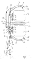
- a generally designated 1, only with the front of the vehicle refuse collection vehicle 1 shown in supervision has a Driver's cabin 2 with a windscreen 3, side windows 4, 4 ' and a vehicle chassis 5.
- a pivotable side arm 6 On the vehicle chassis 5 or whose vehicle frame is not shown separately in the first embodiment according to Fig. 1 is a pivotable side arm 6 arranged to one behind the cab 2 not arranged closer to the chassis 5 or the vehicle frame shown axis is pivotally mounted.
- To the free A coupling piece 8 is articulated at the end 7 of the side arm 6 a lift arm 9 is attached to this via a swivel joint 8a, one of the double brackets, designated overall by reference numeral 10 wearing.
- the double bracket 10 is built on a Base support 11, on this is in a first embodiment in the middle a rigid central web 12 is arranged at right angles to this.
- Movable clamp arms 17, 18 are arranged via swivel joints 15, 16. Both bracket arms 17, 18 are via a toothed segment gear with toothed segments 20, 21 and a coupling linkage 19 as well as deflection plates 22, 22 'and connecting pieces 23, 24 coupled synchronously.
- a hydraulic cylinder 25 which articulated between the lift arm 9 and the connecting piece 24 the bracket arm 18 is arranged, opens and closes the Double bracket 10 as required.
- the operation of the device is as follows: During the forward movement of the refuse collection vehicle 1, the is indicated by the direction arrow 26, the lift arm 9 with the double clamp 10 arranged thereon parallel to Vehicle front and at right angles to the vehicle's longitudinal axis in the Starting position "A" held. To accommodate on the road or Garbage bins parked at the curb and to be emptied 27, 28 the lift arm 9 with the double clamp 10, after the vehicle 1 has been brought to a standstill to the Axis of rotation 8a of the coupling piece 8 around in the receiving position "B" brought, as indicated by the double arrows 29. there the clamp arms 17, 18 are open.
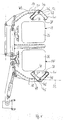
- the double bracket 10 is not, as in Fig. 1, on a movable side arm 6, but on arranged a moving unit 31, which in turn on two arranged on both sides of the driver's cab 2, U-shaped Swivel arms 32, 33, is attached, the shorter legs around one behind the driver's cab 2, for example on the chassis 5 arranged, not shown axis pivotally mounted are, and at the free ends of one end of Coupling pieces 34, 34 'are articulated, one to the front of the vehicle parallel base rail 35 connects to each other.
- the base rail 35 consisting of a box profile a profile tube with a rectangular cross section also longitudinally displaceable guided.
- a hydraulic piston-cylinder unit for retracting and extending the profile tube is a hydraulic piston-cylinder unit in the base rail arranged.
- the moving unit 31 is a parallel Picking up the garbage containers 27, 28 to the front of the vehicle possible. This can be seen in FIG.
- FIG. 3 shows a first embodiment of the double bracket 10 with center bar 12 in the open state, i.e. with outside open clamp arms 17, 18. These have on their inside each friction-increasing agent, namely rubber knobs 37 and highly elastic rubber knobs 38.
- On the basic rack 11 are a pair of pressure plates via a rocker 39 40, 41 articulated.
- the pressure plates 40, 41 are not provided with friction-enhancing means to a perfect lateral displacement of the waste container 27, 28 in the direction of the side walls of the central web 12 at Closing the bracket arms 17, 18 to ensure what by arranging friction-increasing means on the pressure plates 40, 41 would be difficult.
- Double clamp 10 with middle web 12 On the front, free end 44, 45 of the clamp arms 17, 18 is respectively An angle lever 47, 48 can be rotated via a swivel joint 46, 46 ' articulated, the two free ends 49, 50 and 49 ', 50 'also provided with highly elastic rubber knobs 38 is.
- the angle levers 47, 48 are not closer using one shown torsion or leg spring each in the 5 apparent recording position when open Bracket arms 17, 18 held, the two legs 51, 52, 51 ', 52', each at an angle of approximately 45 ° to imaginary axis 53 lying at right angles to the base support 9 the lever arms 17, 18 stand.
- Highly elastic rubber knobs 38 arranged on the one hand at the free ends 49, 49 'of the first Angle lever arms 51, 51 ', and on the other hand at the free end 50, 50 'of the second angle lever arm 52, 52', take care of the required contact pressure to hold the waste container securely 27, 28 in the closed double bracket 10, so that these together with the garbage containers 27, 28 are raised and swiveled into the emptying position can without the garbage container 27, 28 from the double bracket 10 slip out.
- the lever arms 17, 18, which is similar to the first embodiment are configured, an elastic strap on the inside 54, 54 '. This is on the one hand at the foot 55, 55 ' Clamping arms 17, 18 inside, on the other hand on their elongated, inward of the double clamp 10 to the central web 12 facing end pieces 56, 56 'attached to the outer edge.
- the tensioning straps 54, 54 ' run essentially parallel to the central web 12 and to the imaginary longitudinal axis 53 of the clamp arms 17, 18 and the side surfaces of the refuse containers 27, 28.
- the double bracket 10 from two separate independently working brackets 58, 59 is formed. These each have a pair of clamp arms 60, 61 and 60 ', 61' on. In detail, these are analogous to a double bracket 10 formed with central web 12. However, you can be independent be opened and closed from each other, in particular can be of different sizes or contoured differently Garbage containers are hereby captured. Because the footprint experience shows that waste containers 27, 28 are limited, such garbage containers are so close to each other, it is necessary also the two independently working brackets 58, 59 to be arranged as close as possible to each other.
- brackets 58, 59 are to each other offset in areas above or below one another, basically but to be arranged next to each other, whereby they are then in overlap the opening position in some areas, as in Fig. 13 is shown.
- bracket arms 60 'and 61' on two different Levels in such a way that they are equally between two containers 27, 28 provided for emptying and can be moved between them, like a double bracket 10 with center bar 12.
- the gap between two set up Garbage containers 27, 28 can thus be as small as before be kept possible.
- the two brackets 58, 59 can be on a common carrier 62 mounted.
- the Carrier 62 for the clamps 58, 59 already on the refuse collection vehicle existing receptacle 63, 64 for waste containers 27, 28 is.
- an attachment on known claws 63, 64 for waste containers 27, 28 take place to accommodate with a corresponding Collar-equipped waste containers 27, 28 serve in the the receiving claws 63, 64 engage.
- the attachment of the Brackets 58, 59 on the carrier 62 and the receiving claws 63, 64 can be both positive and non-positive.
- To one Hydraulic Quick connector for connecting brackets 58, 59 to the hydraulic system of the refuse collection vehicle 1 is provided his.
Landscapes
- Engineering & Computer Science (AREA)
- Mechanical Engineering (AREA)
- Refuse-Collection Vehicles (AREA)
Abstract
Description
Die Erfindung betrifft ein Müllsammelfahrzeug mit einem Front-/Seitenlader und einer Klammeraufnahme für Müllbehälter.The invention relates to a refuse collection vehicle with a Front / side loader and a clamp holder for waste containers.
Seit langem sind motorbetriebene Müllsammelfahrzeuge bekannt, die heckseitig Schüttungen aufweisen, die jeweils Aufnahmekämme umfassen, auf die entsprechende Müllsammelbehälter aufgehängt werden können. Hierzu ist ein manuelles Aufhängen der Müllbehälter an die Aufnahmekämme durch entsprechendes Ladepersonal erforderlich. Der anschließende Entleerungsvorgang, d.h. das Verschwenken der entsprechenden Hub-Kipp-Vorrichtung wird dann von der jeweiligen Schüttung automatisch über einen entsprechenden Hydraulikantrieb durchgeführt. Neben hohem Personaleinsatz und zahlreichen Unfall- und Verletzungsgefahren weist diese Lösung auch den Nachteil relativ ineffizienter Arbeitsweise auf.Motorized refuse collection vehicles have been known for a long time, which have fillings at the rear, each with combs include, hung on the appropriate garbage can can be. To do this, manually hang the Garbage containers to the pick-up combs by appropriate loading personnel required. The subsequent emptying process, i.e. the pivoting of the corresponding lifting and tilting device is then automatically transferred from the respective fill a corresponding hydraulic drive performed. Next high level of personnel and numerous accidents and injuries this solution also has the disadvantage relatively inefficient way of working.
Aus diesem Grunde sind, wie beispielsweise aus der EP 0 163 859 B1, auch bereits Müllsammelfahrzeuge mit einer Schütteinheit bekannt, die aus einer im vorderen Bereich des Fahrzeugs angeordneten Einschüttöffnung, die sich teils oberhalb des Führerhauses des Müllsammelfahrzeuges und teils zwischen diesem und einem Container in dem Bereich hinter und oberhalb des Führerhauses befindet und einem Aufnahmeraum bestehen.For this reason, as for example from EP 0 163 859 B1, also already refuse collection vehicles with a dump unit known from a in the front of the vehicle arranged pouring opening, which is partly above of the cab of the refuse collection vehicle and partly between this and a container in the area behind and above of the cab and a recording room.
Weiterhin ist auch hier eine Hub-Kipp-Vorrichtung zur Aufnahme und zur Entleerung von Müllbehältern in die Einschüttöffnung vorgesehen. Die in der EP 0 163 859 B1 beschriebenen Müllsammelfahrzeuge weisen einen eine Aufnahmeklaue für Müllbehälter tragenden Schwenkarm auf, der auf einem Träger oder Hohlprofil, das wiederum auf der Grundschiene über mindestens ein Ende derselben ausfahrbar verschieblich gelagert ist, angeordnet ist. Mittels dieser verschwenkbaren Aufnahmeklaue lassen sich vorher bereit gestellte Müllbehälter vollautomatisch und einfach an die Hub-Kipp-Vorrichtung ankoppeln und in die Einschüttöffnung entleeren, ohne dass zusätzlich Müllwerker eingreifen müssen, so daß die Einsammelarbeit von dem Fahrer allein durchgeführt werden kann. Sowohl bei dieser Lösung mit einer sogenannten Verfahreinheit wie auch mit einer weiteren, beispielsweise aus der US 5,711,565 bekannten Lösung, bei der im Frontbereich eines Müllsammelfahrzeuges ein schwenkbarer Seitenarm mit einer Greifeinrichtung vorgesehen ist, kann jeweils immer nur ein einzelner Müllbehälter aufgenommen und entleert werden.Furthermore, a lifting and tilting device for receiving is also here and for emptying garbage containers into the pouring opening intended. Those described in EP 0 163 859 B1 Garbage collection vehicles have a pick-up claw for garbage containers supporting swivel arm on a carrier or Hollow section, which in turn on the base rail over at least one end of the same is slidably mounted, extendable is. By means of this swiveling pick-up claw previously provided waste containers can be fully automated and simply connect to the lift and tilt device and empty into the pouring opening without additional waste workers have to intervene so that the collection work of the Driver can be done alone. Both with this solution with a so-called travel unit as well as with a further solution known for example from US Pat. No. 5,711,565, at the front of a refuse collection vehicle pivotable side arm provided with a gripping device only a single waste container can be picked up at a time and be emptied.
Aufgabe der Erfindung ist es daher, die vorhandenen Möglichkeiten zu verbessern, und weitere Rationalisierungsmöglichkeiten zu erschließen, indem bei ausschließlicher Bedienung des Müllsammelfahrzeuges durch den Fahrer mehrere Müllbehälter gleichzeitig entleert und in die Bereitstellungsposition zurückgesetzt werden können. The object of the invention is therefore the available possibilities improve, and more rationalization opportunities to be tapped by operating exclusively of the refuse collection vehicle by the driver several refuse containers emptied at the same time and into the ready position can be reset.
Eine weitere Aufgabe besteht darin, eine weitergehende Flexibilisierung zu erreichen, insbesondere was die gleichzeitige Aufnahme verschiedener Müllbehälter, insbesondere von Müllbehältern mit unterschiedlicher Größe und/oder Außenkonturen betrifft, und gleichzeitig die bisher auf dem Markt bekannten Systeme miteinander kompatibel zu machen, um beispielsweise in einem Müllsammelbezirk oder auf einer Tour mit demselben Fahrzeug auch unterschiedliche Müllgefäßtypen entleeren zu können.Another task is further flexibility to achieve, especially what the simultaneous Various garbage containers, in particular garbage containers with different sizes and / or outer contours concerns, and at the same time those previously known on the market To make systems compatible with each other, for example in a garbage collection district or on a tour with the same The vehicle also empties different types of waste containers can.
Diese Aufgabe wird gemäß der Erfindung dadurch gelöst, daß eine Doppelklammer zur gleichzeitigen Aufnahme von zwei Müllbehältern an einem Front-/Seitenlader vorgesehen ist.This object is achieved according to the invention in that a double clamp to hold two garbage bins at the same time is provided on a front / side loader.
Mit einer derartigen Doppelklammer ist es möglich, zwei Müllgefäße zur gleichen Zeit am gleichen Ort aufzunehmen, zu entleeren und entleert wieder abzusetzen. Dabei müssen beide Müllgefäße nicht notwendigerweise miteinander identisch sein, wenngleich dies die Handhabung erleichtert. Die Doppelklammervorrichtung ist sowohl mit einem Front-/ Seitenladersystem mit einer Verfahreinheit wie auch mit einem Müllsammelfahrzeug mit schwenkbarem Seitenarm kombinierbar. Die Verfahreinheit gestattet ein paralleles Aufnehmen der Müllgefäße zur Fahrzeugvorderseite. Bei Anbau der erfindungsgemäßen Doppelklammer kann diese rechtwinkelig zur Fahrzeugvorderseite geschwenkt werden, um dann anschließend parallel zur Fahrzeugvorderseite auf die am Straßenrand befindlichen Müllbehältern zuzufahren.With such a double clamp, it is possible to have two waste containers to empty at the same time in the same place and emptied to put down again. Both must Garbage cans are not necessarily identical to each other, although this makes handling easier. The double clamp device is both with a front / side loader system with a moving unit as well as with a refuse collection vehicle can be combined with a swiveling side arm. The moving unit allows the garbage containers to be picked up in parallel Front of the vehicle. When mounting the double bracket according to the invention can be pivoted at right angles to the front of the vehicle then in parallel to the front of the vehicle on the rubbish bins on the side of the road to drive.
Bei Kombination mit Doppelklammern und einem schwenkbaren Seitenarm, insbesondere einem schwenkbaren Seitenarm, insbesondere einem einarmigen Liftgerüst, wie es aus der US 5,711,565 bekannt ist, kann die Doppelklammer individuell in die verschiedensten Winkelpositionen gebracht werden, so daß immer ein paralleles Aufnehmen der Müllbehälter, entweder parallel zur Fahrzeugvorderseite oder auch zur Fahrzeugslängsachse, durchgeführt werden kann. Aufgrund einer hydraulischen Verstellmöglichkeit der Behälteraufnahme ist es darüberhinaus auch möglich, schrägstehende Müllbehälter zu erfassen, so daß es auch möglich ist, ein Schwenken aus der Parallelität heraus zuzulassen.When combined with double clamps and a swiveling one Side arm, in particular a pivotable side arm, in particular a one-arm lift scaffold, as it is from the US 5,711,565 is known, the double bracket can be individually in the various angular positions are brought so that always picking up the waste bins in parallel, either in parallel to the front of the vehicle or to the longitudinal axis of the vehicle, can be carried out. Because of a hydraulic It is also possible to adjust the container holder also possible to detect inclined waste containers, so that it is also possible to swivel out of parallelism allow.
In vorteilhafter Ausgestaltung ist vorgesehen, daß die Doppelklammer einen feststehenden Mittelsteg aufweist. Hierdurch wird eine feste Anlageschulter für beide aufzunehmende Müllbehälter beidseits des Mittelsteges geschaffen.In an advantageous embodiment it is provided that the double bracket has a fixed central web. Hereby will be a firm investment shoulder for both Rubbish bins created on both sides of the central web.
Bei einer alternativen Ausgestaltung ist vorgesehen, daß die Doppelklammer aus zwei voneinander getrennten unabhängig arbeitenden Klammern gebildet ist, was insbesondere die Aufnahme unterschiedlich dimensionierter und/oder außenkonturierter Müllbehälter erleichtert. In an alternative embodiment it is provided that the Double brackets made up of two separate working independently Brackets is formed, which is particularly the inclusion differently dimensioned and / or contoured outside Garbage container made easier.
Der Mittelsteg kann, ebenso wie die beweglichen Klammerarme, in vorteilhafter Ausgestaltung mit zu den Müllbehältern weisenden reibungserhöhenden Mitteln, insbesondere Gumminoppen und/oder hochelastischen Gumminoppen ausgerüstet sein.The center bar, like the movable clamp arms, in an advantageous embodiment with the garbage containers facing friction-increasing agents, especially rubber knobs and / or highly elastic rubber knobs.
In einer weiteren Ausgestaltung ist vorgesehen, daß die Klammerarme an ihren freien Enden mit der Außenkontur der aufzunehmenden Müllbehälter angepaßten Winkelhebeln versehen sind. Derartige Winkelhebel, die beispielsweise durch Torsions-und/oder Schenkelfedern in Position gehalten werden, umklammern den bzw. die aufzunehmenden Müllbehälter auf der vorderen, von der offenen Aufnahmeseite der im wesentlichen in Aufsicht U-förmig ausgestalteten Doppelklammerhälften her und legen sich beim Schließen der Klammern an der Vorderseite des jeweiligen Müllbehälters fest, so daß ein Hinausrutschen des Müllbehälters nach vorne aus der Doppelklammer heraus mechanisch unmöglich gemacht wird.In a further embodiment it is provided that the clamp arms at their free ends with the outer contour of the to be recorded Waste bins are fitted with angle levers. Such angle levers, for example, by torsion and / or Leg springs are held in place, clasp the bin (s) to be picked up on the front, from the open receiving side which is essentially in Top view U-shaped double bracket halves ago and lay down when closing the brackets on the front of the respective garbage container firmly, so that a slipping out of the Garbage bin mechanically out of the double clamp is made impossible.
In einer weiteren Ausgestaltung ist vorgesehen, daß auch die Winkelhebel mit hochelastischen Gumminoppen ausgestattet sind. Die reibungserhöhenden Mittel, insbesondere Gumminoppen, verhindern ein Hinaus- und/oder Verrutschen der Behälter während des Anhebens derselben bzw. während der Hub-/Kipp-Bewegung einschließlich des Entleerens des Behälterinhaltes in den Aufnahmeraum des Müllsammelfahrzeuges. In a further embodiment it is provided that the Angle lever equipped with highly elastic rubber knobs are. The friction-increasing agents, especially rubber knobs, prevent the containers from slipping out and / or slipping during the lifting thereof or during the lifting / tilting movement including emptying the contents of the container in the receiving room of the refuse collection vehicle.
Diesem Zweck dienen auch elastische Spannbänder, die innenseitig an den Klammerarmen angeordnet sein können. Beim Zusammenklappen der hydraulisch oder pneumatisch betätigten Klammerarme legen sich die elastischen Spannbänder zumindest bereichsweise um die Außenkonturen der eingespannten Müllbehälter. Durch dieses zusätzliche Einspannen der Müllbehälter werden diese ebenfalls an einem Heraus- und/oder Verrutschen während des Hub-/Kippvorganges gehindert. Zusätzlich unterstützt wird der Halt der Müllbehälter in der jeweiligen Doppelklammerhälfte durch eine auf die Behälterrückwand wirkenden, sich selbst justierenden, an sich bekannte Andruckplatte. Sobald sich die Klammerarme um die Behälter schließen, werden diese in diagonaler Richtung zur Grundaufhängung der Doppelklammer hin gedrängt, bis sie in der endgültigen Aufnahmestellung an die Andruckplatten anstoßen. Die Klammerarme und die Spanner wirken zusammen, um ein Auswandern der Müllbehälter in Längsrichtung zu deren Achse in aufrechter Stellung, in bezug auf die Klammerarme und Andruckplatte während des Hub-/Kippvorganges zu verhindern. Erst wenn der Entleerungsvorgang abgeschlossen ist und die Behälter in die ursprüngliche Aufnahmestellung zurückgesetzt sind, werden sie von den pneumatisch oder hydraulisch betätigten, sich öffnenden Klammerarmen wieder freigegeben. Die Verfahreinheit oder der schwenkbare Seitenarm, an denen die Doppelklammer angeordnet sein kann, fährt sodann in die Grundstellung am Müllsammelfahrzeug zurück, dieses bewegt sich fort bis zum nächstgelegenen Aufstellort für zu entleerende Müllbehälter, wo die zuvor beschriebene Routine von vorne beginnt. Dabei kann der gesamte Aufnahme-, Entleerungs- und Zurückstellprozeß allein durch den Fahrer des Müllsammelfahrzeuges gesteuert werden, ohne dass es des Einsatzes weiterer Müllwerker bedarf.This purpose is also served by elastic straps on the inside can be arranged on the bracket arms. When collapsing the hydraulically or pneumatically operated The elastic straps at least lay down clamp arms in some areas around the outer contours of the clamped waste containers. This additional clamping of the garbage can they will also slide out and / or slip hindered during the lifting / tipping process. Additionally supported becomes the stop of the waste container in the respective double clamp half through an effect on the rear wall of the container self-adjusting, known pressure plate. As soon as the clamp arms close around the containers, these become the basic suspension of the Double bracket pushed until it is in the final recording position knock against the pressure plates. The bracket arms and the tensioners work together to emigrate the garbage containers in the longitudinal direction to its axis in an upright position, with respect to the clamp arms and pressure plate while to prevent the lifting / tipping process. Only when the emptying process is complete and the container in the original Are reset, they will of the pneumatically or hydraulically operated, opening ones Clamp arms released again. The travel unit or the swiveling side arm on which the double clamp is arranged can then be in the basic position on the refuse collection vehicle back, this continues until nearest installation site for waste containers to be emptied, where the previously described routine starts over. there can do the entire intake, drain and reset process controlled solely by the driver of the refuse collection vehicle without the use of additional garbage workers requirement.
Um die Steuerungshydraulik bzw. -pneumatik zu vereinfachen, ist auch vorgesehen, daß die Klammerarme mechanisch über ein Koppelgestänge und ein Zahnsegmentgetriebe miteinander verbunden sind. Dadurch ist nur ein einziger Hydraulik- bzw. Pneumatikzylinder zur Betätigung der gesamten Doppelklammer erforderlich.In order to simplify the control hydraulics and pneumatics, it is also provided that the clamp arms mechanically over a Coupling linkage and a toothed segment gear connected to each other are. This means that only a single hydraulic or Pneumatic cylinder for actuating the entire double clamp required.
Um die gleichzeitige Aufnahme von Müllbehältern zu ermöglichen, können die zwei Klammern nebeneinander angeordnet sein, sie können aber, insbesondere um unterschiedlichen Größenverhältnissen von Müllbehältern zu entsprechen, auch unter- bzw. übereinander angeordnet sein.To enable the simultaneous collection of waste containers, the two brackets can be arranged side by side, but they can, in particular to different size ratios of garbage containers, including under or be arranged one above the other.
Dabei werden beide Klammern zweckmäßig zueinander versetzt angeordnet, so daß sie sich in der Öffnungsstellung bereichsweise übergreifen. Dadurch, daß eine der beiden Klammern höher, die andere niedriger angeordnet ist, können diese sich in der Aufnahmestellung überlappen. Dies ist notwendig, um den Spalt, d.h. den Abstand zwischen den beiden zum Entleeren bereitgestellten Behältern möglichst gering zu halten, also den benötigten Platz minimieren zu können.Both brackets are appropriately offset from each other arranged so that they are partially in the open position spread. Because one of the two brackets is higher, the other is lower, they can be different overlap in the recording position. This is necessary to the gap, i.e. the distance between the two for emptying keep containers provided as low as possible, that is to be able to minimize the space required.
Weiterhin ist vorgesehen, dass beide Klammern auf einem gemeinsamen Träger montierbar sind. Vorteilhaft ist es dabei, wenn es sich bei diesem Träger um eine ihrerseits zur Aufnahme von Müllbehältern vorgesehene Aufnahme handelt. In diesem Fall können die Klammern auf eine für bestimmte Behältertypen geeignete bereits am Müllsammelfahrzeug vorhandene Behälteraufnahme montiert werden, um anders geartete Behälter, die mit der in der Grundausstattung am Müllsammelfahrzeug vorhandenen Aufnahme nicht kompatibel sind, ebenfalls aufnehmen und entleeren zu können.It is also provided that both brackets on a common Carrier are mountable. It is advantageous if this carrier is in turn for admission receptacle intended for waste containers. In this The brackets can fall on one for certain container types Suitable container receptacle already on the refuse collection vehicle be assembled to different types of containers that with the existing equipment on the refuse collection vehicle Recording are not compatible, also record and to be able to empty.
Durch den Einsatz hydraulischer Schnellkuppler kann eine Schnellmontage der beiden Klammern auf einer solchen bereits vorhandenen Aufnahme oder einem geeigneten anderen Träger und die notwendige Verbindung mit dem Hydraulik-System des Fahrzeugs erreicht werden. Für die mechanische Verbindung ist entweder eine formschlüssige oder - alternativ hierzu - eine kraftschlüssige Befestigung der Klammern auf dem Träger vorgesehen.By using hydraulic quick couplers, a Quick assembly of the two brackets on one already existing recording or a suitable other carrier and the necessary connection with the hydraulic system of the vehicle can be achieved. For the mechanical connection is either a form-fitting or - alternatively - one non-positive attachment of the clips provided on the carrier.
Vorteilhaft ist es, wenn die Klammern in der Transportlage zusammenfaltbar sind, wobei dieser Vorgang aus Sicherheitsgründen bei Überschreiten eines bestimmten Schwenkwinkels auch automatisch ausgelöst werden kann, um Beschädigungen aufgrund zu geringer Durchfahrthöhen oder dgl. zu vermeiden.It is advantageous if the clips in the transport position are collapsible, this process for security reasons when a certain swivel angle is exceeded can also be triggered automatically to damage to avoid due to insufficient headroom or the like.
Die Erfindung ist nachstehend anhand der Zeichnung näher erläutert. Diese zeigt in
- Fig. 1
- eine Aufsicht auf ein bereichsweise mit der Fahrzeugfront dargestellten Müllsammelfahrzeug mit einem schwenkbaren Seitenarm und einer daran angeordneten, erfindungsgemäßen Doppelklammer mit Mittelsteg,
- Fig. 2
- eine Aufsicht auf ein bereichsweise mit der Fahrzeugfront dargestellten Müllsammelfahrzeug mit einem zweiarmigen Liftgerüst, einer Verfahreinheit und einer daran angeordneten erfindungsgemäßen Doppelklammer mit Mittelsteg in mehreren Positionen,
- Fig. 3
- eine Aufsicht auf eine erste Ausführungsform einer erfindungsgemäßen Doppelklammer mit Mittelsteg im im geöffneten Zustand,
- Fig. 4
- eine Aufsicht auf eine erfindungsgemäße Doppelklammer gemäß Fig. 3 im geschlossenen Zustand,
- Fig. 5
- eine Aufsicht auf eine zweite Ausführungsform einer erfindungsgemäßen Doppelklammer mit Mittelsteg im geöffneten Zustand,
- Fig. 6
- eine Aufsicht auf eine erfindungsgemäße Doppelklammer gemäß Fig. 5 im geschlossenen Zustand,
- Fig. 7
- eine weitere Ausführungsform einer erfindungsgemäßen Doppelklammer mit Mittelsteg mit einem Spannband im geöffneten Zustand,
- Fig. 8
- eine Aufsicht auf eine erfindungsgemäße Doppelklammer gemäß Fig. 7 im geschlossenen Zustand,
- Fig. 9
- eine Aufsicht auf eine erfindungsgemäße Doppelklammer mit Mittelsteg für den Anbau an einer Verfahreinheit im geöffneten Zustand,
- Fig. 10
- eine Aufsicht auf eine erfindungsgemäße Doppelklammit zwei voneinander getrennten unabhängig arbeitenden Klammern in geschlossener Transportstellung,
- Fig. 11
- eine Aufsicht auf eine Doppelklammer gemäß Fig. 10 im Eingriff auf zwei gleichgroßen Müllbehältern,
- Fig. 12
- eine Aufsicht auf eine Doppelklammer gemäß Fig. 10
und 11 mit zwei kleineren Müllbehältern, - Fig. 13
- eine Aufsicht auf eine Doppelklammer mit zwei voneinander getrennten unabhängig arbeitenden zueinander versetzt bereichsweise unter- bzw. übereinander in Öffnungsstellung bereichsweise übergreifenden Klammern,
- Fig. 14
- eine Aufsicht auf eine Doppelklammer gemäß Fig. 10 mit einer Klammer in geschlossener Transportstellung und einer Klammer in halbgeöffnetem Zustand.
- Fig. 1
- 1 shows a top view of a refuse collection vehicle, shown in some areas with the vehicle front, with a pivotable side arm and a double clamp according to the invention with a central web arranged thereon,
- Fig. 2
- 1 shows a top view of a refuse collection vehicle with a two-armed lift scaffold, a moving unit and a double clamp according to the invention with a central web in several positions, shown with the front of the vehicle,
- Fig. 3
- 2 shows a top view of a first embodiment of a double clamp according to the invention with a central web in the open state,
- Fig. 4
- 3 shows a top view of a double clamp according to the invention according to FIG. 3 in the closed state,
- Fig. 5
- 2 shows a top view of a second embodiment of a double clip according to the invention with a central web in the open state,
- Fig. 6
- 5 shows a top view of an inventive double clamp according to FIG. 5 in the closed state,
- Fig. 7
- another embodiment of a double clamp according to the invention with a central web with a tensioning strap in the open state,
- Fig. 8
- 7 is a plan view of a double clamp according to the invention according to FIG. 7 in the closed state,
- Fig. 9
- 1 is a top view of a double clamp according to the invention with a central web for attachment to a moving unit in the open state,
- Fig. 10
- 1 is a top view of a double clamp according to the invention with two independently working clamps in the closed transport position,
- Fig. 11
- 10 is a top view of a double clamp according to FIG. 10 in engagement with two garbage containers of the same size,
- Fig. 12
- 10 and 11 with two smaller garbage containers,
- Fig. 13
- 1 a top view of a double clamp with two mutually separate, independently working clamps offset from one another in certain regions, one above the other or one above the other in the open position,
- Fig. 14
- 10 with a clip in the closed transport position and a clip in the half-open state.
Ein allgemein mit 1 bezeichnetes, nur mit der Fahrzeugfront
in Aufsicht dargestelltes Müllsammelfahrzeug 1 weist eine
Fahrerkabine 2 mit einer Frontscheibe 3, Seitenscheiben 4, 4'
und einem Fahrzeugchassis 5 auf. An dem Fahrzeugchassis 5
bzw. dessen nicht gesondert dargestelltem Fahrzeugrahmen ist
in erster Ausgestaltung gem. Fig. 1 ein schwenkbarer Seitenarm
6 angeordnet, der um eine hinter dem Führerhaus 2 an
dem Chassis 5 bzw. dem Fahrzeugrahmen angeordnete, nicht näher
dargestellte Achse schwenkbar gelagert ist. An das freie
Ende 7 des Seitenarms 6 ist ein Koppelstück 8 angelenkt, an
diesem ist über ein Drehgelenk 8a ein Liftarm 9 befestigt,
der eine insgesamt mit dem Bezugszeichen 10 bezeichnete Doppelklammer
trägt. Die Doppelklammer 10 ist aufgebaut auf einem
Grundträger 11, an diesem ist in erster Ausgestaltung
mittig ein starrer Mittelsteg 12 rechtwinkelig hierzu angeordnet.
An den freien Enden 13, 14 des Grundträgers 11 sind
über Drehgelenke 15, 16 bewegliche Klammerarme 17, 18 angeordnet.
Beide Klammerarme 17, 18 sind über ein Zahnsegmentgetriebe
mit Zahnsegmenten 20, 21 und ein Koppelgestänge 19
sowie Umlenkplatten 22, 22', sowie Verbindungsstücke 23, 24
synchron miteinander gekoppelt. Ein Hydraulikzylinder 25, der
gelenkig zwischen dem Liftarm 9 und dem Verbindungsstück 24
des Klammerarms 18 angeordnet ist, öffnet und schließt die
Doppelklammer 10 nach Bedarf.A generally designated 1, only with the front of the vehicle
refuse
Die Wirkungsweise der Vorrichtung ist dabei die folgende:
Während der Vorwärtsbewegung des Müllsammelfahrzeuges 1, die
mit dem Richtungspfeil 26 angezeigt ist, wird der Liftarm 9
mit der daran angeordneten Doppelklammer 10 parallel zur
Fahrzeugfront und rechtwinkelig zur Fahrzeuglängsachse in der
Ausgangsstellung "A" gehalten. Zur Aufnahme von am Straßen-oder
Bordsteinrand abgestellten, zu entleerenden Müllbehältern
27, 28 wird der Liftarm 9 mit der Doppelklammer 10,
nachdem das Fahrzeug 1 zum Stillstand gebracht wurde, um die
Drehachse 8a des Koppelstücks 8 herum in die Aufnahmeposition
"B" gebracht, wie mit den Doppelpfeilen 29 angedeutet. Dabei
sind die Klammerarme 17, 18 geöffnet. Sobald sich der Mittelsteg
12 zwischen zwei entsprechend bereit gestellte Müllbehälter
27, 28 geschoben hat, werden die Klammerarme 17, 18
durch Betätigung des Hydraulikzylinders 25 geschlossen, und
umfassen nunmehr die Müllbehälter 27, 28. Durch ein geringfügiges
Anheben des schwenkbaren Seitenarmes 6 werden die
Müllbehälter 27, 28 vom Erdboden bzw. von der Straßenoberfläche
angehoben, anschließend wird der Liftarm 9 mit der
Doppelklammer 10 und den von dieser ergriffenen Müllbehältern
27, 28 in die Ausgangsstellung "A" zurückgeschwenkt. Sodann
beginnt das weitere Anheben der Behälter 27, 28 mittels einer
Aufwärtsbewegung des seitlichen Schwenkarmes 6, was durch den
Doppelpfeil 30 angedeutet ist, in die Entleerungsstellung "C"
über die Fahrerkabine 2 des Müllsammelfahrzeuges 1 hinweg zur
nicht näher dargestellten Einfüllöffnung für den ebenfalls
nicht näher dargestellten Müllaufnahmeraum bzw. -container
des Fahrzeugs 1. Nach der Entleerung der Behälter 27, 28,
wird der Seitenarm 6, wie mit dem Doppelpfeil 30 dargestellt,
wieder in die Grundposition "A" zurückverschwenkt. Daran anschließend
klappt der Liftarm 9 mit der Doppelklammer 10 und
den hiervon gehaltenen, nunmehr entleerten Müllbehältern 27,
28, wie mit dem Doppelpfeil 29 angedeutet, in die Aufnahme-und
Abstellposition "B" zurück. Der Hydraulik- bzw. Pneumatikzylinder
25 wird erneut betätigt, um die Klammerarme 17,
18 zu öffnen und die Müllbehälter 27, 28 am Straßenrand bzw.
Bordsteinrand wieder abzustellen. Anschließend schwenkt die
geöffnete Doppelklammer 10 mit dem Liftarm 9 in die Ausgangsposition
"A" zurück und das Müllsammelfahrzeug bewegt
sich in die mit dem Pfeil 26 dargestellte Fahrtrichtung fort,
um zu den nächsten Müllbehältern zu gelangen, wo sich die
vorstehend beschriebene Prozedur wiederholt.The operation of the device is as follows:
During the forward movement of the
In Ausgestaltung ist die Doppelklammer 10 nicht, wie in Fig.
1 dargestellt, an einem beweglichen Seitenarm 6, sondern an
einer Verfahreinheit 31 angeordnet, die ihrerseits an zwei
beidseits der Fahrerkabine 2 angeordneten, U-förmigen
Schwenkarmen 32, 33, befestigt ist, deren kürzere Schenkel um
eine hinter der Fahrerkabine 2 beispielsweise an dem Chassis
5 angeordnete, nicht näher dargestellte Achse schwenkbar gelagert
sind, und an deren freien Enden die einen Enden von
Koppelstücken 34, 34' angelenkt sind, die eine zur der Fahrzeugfront
parallele Grundschiene 35 miteinander verbindet.
Die anderen Enden der Koppelstücke 34, 34' sind gelenkig mit
Lenkern eines Lenker-Hebelsystems verbunden, das die Drehbewegung
der Grundschiene beim Verschwenken der Hubarme derart
steuert, daß diese bis zum Verschwenken in Höhe des oberen
Bereichs der Fahrerkabine im wesentlichen etwa relativ zu dem
Müllsammelfahrzeug keine Drehung ausführt.In an embodiment, the
Auf der aus einem Kastenprofil bestehende Grundschiene 35 ist
ein Profilrohr mit ebenfalls rechteckigen Querschnitt längsverschieblich
geführt. Zum Ein- und Ausfahren des Profilrohrs
ist in der Grundschiene eine hydraulische Kolben-Zylinder-Einheit
angeordnet. Auf dem Profilrohr sind ein Hauptlenker
und ein Hilfslenker schwenkbar gelagert, deren anderen
Enden gelenkig mit einem Koppelstück verbunden sind, an das
die bereits gemäß Fig. 1 beschriebene Doppelklammer 10 beweglich
angelenkt ist. Mit der Verfahreinheit 31 ist ein paralleles
Aufnehmen der Müllbehälter 27, 28 zur Fahrzeugvorderseite
möglich. Damit kann bei dieser aus der Fig. 2 ersichtlichen
Ausgestaltung aus einer Position "A" heraus die Doppelklammer
10 rechtwinkelig zur Fahrzeugvorderseite in die
Position "B" geschwenkt werden und fährt dann parallel zur
Fahrzeugvorderseite auf die am Straßen- bzw. Bordsteinrand
befindlichen Müllbehälter 27, 28 zu, wie dies mit dem Pfeil
36 dargestellt ist.On the
Fig. 3 bis 9 zeigen verschiedene Ausführungsformen der Mittelsteg-Version
der Doppelklammer 10 im Detail.3 to 9 show different embodiments of the center bar version
the
So zeigt Fig. 9 einen speziellen Träger 11 zur Anordnung der
Doppelklammer 10 an einer Verfahreinheit 31, wobei der Hydraulikzylinder
25 in einer modifizierten Position zur Anbindung
an die Verfahreinheit 31 angeordnet ist.9 shows a
Fig. 3 zeigt eine erste Ausführungsform der Doppelklammer 10
mit Mittelsteg 12 im geöffneten Zustand, d.h. mit nach außen
aufgefahrenen Klammerarmen 17, 18. Diese weisen auf ihrer Innenseite
jeweils reibungserhöhende Mittel, nämlich Gumminoppen
37 und hochelastische Gumminoppen 38 auf. An dem Grundträger
11 sind über eine Wippe 39 jeweils ein Paar von Andruckplatten
40, 41 beweglich angelenkt. Beim Schließen der
Klammerarme 17, 18 werden die Müllbehälter 27, 28 in Richtung
auf die Andruckplatten 40, 41 gepreßt und im vorderen Eckbereich
42, 43 der Müllbehälter 27, 28 von dem abgewinkelten,
freien Ende 44, 45 der Klammerarme 17, 18 umschlossen. Dabei
werden die Müllbehälter 17, 18 gleichzeitig in Richtung des
Mittelsteges 12 gedrückt, der beidseitig ebenso wie die Innenseite
der Klammerarme 17, 18 mit reibungserhöhenden Mitteln,
insbesondere Gumminoppen 37 versehen ist. Diese Gumminoppen
verhindern ein Auswandern oder Hinausrutschen der Behälter
27, 28 während des folgenden Anhebens. Um den Andruckeffekt
zu erhöhen, sind zumindest an der Innenseite der
freien Enden 44, 45 der Klammerarme 17, 18 zusätzlich oder
alternativ zu den Gumminoppen 37 hochelastische Gumminoppen
38 vorgesehen. Die Andruckplatten 40, 41 hingegen sind nicht
mit reibungserhöhenden Mitteln versehen, um eine möglichst
einwandfreie seitliche Verschiebbarkeit der Müllbehälter 27,
28 in Richtung auf die Seitenwände des Mittelsteges 12 beim
Schließen der Klammerarme 17, 18 hin zu gewährleisten, was
durch die Anordnung reibungserhöhender Mittel an den Andruckplatten
40, 41 erschwert würde.3 shows a first embodiment of the
Fig. 5 und 6 zeigen eine zweite Ausführungsform der erfindungsgemäßen
Doppelklammer 10 mit Mittelsteg 12. An dem vorderen,
freien Ende 44, 45 der Klammerarme 17, 18 ist jeweils
über ein Drehgelenk 46, 46' ein Winkelhebel 47, 48 drehbar
angelenkt, der an seinen beiden freien Enden 49, 50 und 49',
50' ebenfalls mit hochelastischen Gumminoppen 38 versehen
ist. Die Winkelhebel 47, 48 sind mit Hilfe einer nicht näher
dargestellten Torsions- oder Schenkelfeder jeweils in der aus
der Fig. 5 ersichtlichen Aufnahmestellung bei geöffneten
Klammerarmen 17, 18 gehalten, wobei die beiden Schenkel 51,
52, 51', 52', jeweils in einem Winkel von etwa 45° zur
rechtwinkelig zum Grundträger 9 liegenden gedachten Achse 53
der Hebelarme 17, 18 stehen. Sobald sich die Hebelarme 17, 18
der Doppelklammer 10 schließen, und dabei jeweils einen Müllbehälter
27, 28 umschließen, wird der Winkelhebelarm 51, 51'
durch die Außenkontur des jeweiligen Müllbehälters 27, 28 in
Richtung der Längsachse 53 des jeweiligen Hebelarms 17, 18
gedrückt, bis er schließlich völlig parallel hierzu steht.
Hierdurch bedingt wird der zum Winkelhebelarm 51, 51' starre,
in einem Winkel von beispielsweise 90° angeordnete zweite
Winkelhebelarm 52, 52' in Richtung auf die vordere, freie
Seite 54, 54' der Müllbehälter 27, 28 nachgeführt und parallel
zu dieser festgelegt. Hochelastische Gumminoppen 38,
angeordnet einerseits an den freien Enden 49, 49' des ersten
Winkelhebelarms 51, 51', und andererseits an dem freien Ende
50, 50' des zweiten Winkelhebelarms 52, 52', sorgen für den
erforderlichen Anpreßdruck, um einen sicheren Halt der Müllbehälter
27, 28 in der geschlossenen Doppelklammer 10 zu erreichen,
so daß diese mitsamt der Müllbehälter 27, 28 angehoben
und in die Entleerungsstellung verschwenkt werden
kann, ohne daß die Müllbehälter 27, 28 aus der Doppelklammer
10 herausrutschen.5 and 6 show a second embodiment of the
In einer dritten Ausführungsform ist vorgesehen, daß die Hebelarme
17, 18, die ähnlich wie in der ersten Ausführungsform
ausgestaltet sind, innenseitig ein elastisches Spannband
54, 54' aufweisen. Dieses ist einerseits am Fuß 55, 55' der
Klammerarme 17, 18 inwendig, andererseits an deren verlängerten,
einwärts der Doppelklammer 10 zum Mittelsteg 12
weisenden Endstücke 56, 56' außenrandseitig befestigt. In der
Aufnahmestellung der entsprechend ausgerüsteten Doppelklammer
10 verlaufen die Spannbänder 54, 54' im wesentlichen parallel
zum Mittelsteg 12 und zur gedachten Längsachse 53 der Klammerarme
17, 18 sowie der Seitenflächen der Müllbehälter 27,
28. Werden die Klammerarme 17, 18 geschlossen, so legen sich
die Spannbänder 54, 54' vollflächig an die jeweils vom Mittelsteg
12 wegweisende Außenwandung des jeweiligen Müllbehälters
27, 28 an und werden gleichzeitig um die vordere Ecke
42, 43 des jeweiligen Müllbehälters 27, 28 bis hin zum Anlagepunkt
57, 57' des Verlängerungsstücks 56, 56' der Klammerarme
17, 18 herumgeführt. Auf diese Weise werden die Müllbehälter
27, 28 ebenfalls sicher gehalten und an einem Auswandern
bzw. Hinausrutschen aus der Doppelklammer 10 während des
Anhebens und des gesamten Entleerungsvorganges gehindert.In a third embodiment it is provided that the
Bei einer zweiten, alternativen Ausführungsform ist vorgesehen,
daß die Doppelklammer 10 aus zwei voneinander getrennten
unabhängig arbeitenden Klammern 58, 59 gebildet ist.
Diese weisen jeweils ein Paar Klammerarme 60, 61 und 60', 61'
auf. Diese sind im einzelnen Analog zu einer Doppelklammer 10
mit Mittelsteg 12 ausgebildet. Sie können jedoch unabhängig
voneinander geöffnet und geschlossen werden, insbesondere
können unterschiedlich große oder bzw. unterschiedlich konturierte
Müllgefäße hiermit erfaßt werden. Da die Aufstellfläche
für Müllbehälter 27, 28 erfahrungsgemäß begrenzt ist,
derartige Müllgefäße also nah aneinander stehen, ist es erforderlich,
auch die beiden unabhängig arbeitenden Klammern
58, 59 möglichst nah zueinander anzuordnen. Besonders vorteilhaft
ist es dabei, die beiden Klammern 58, 59 zueinander
versetzt bereichsweise unter- bzw. übereinander, grundsätzlich
aber nebeneinander anzuordnen, wobei sie sich dann in
der Öffnungsstellung bereichsweise übergreifen, wie dies in
Fig. 13 dargestellt ist. Bei einer derartigen Anordnung überlappen
sich die Klammerarme 60' und 61' auf zwei verschiedenen
Ebenen in der Weise, daß sie in gleicher Weise zwischen
zwei zur Entleerung bereit gestellten Behälter 27, 28 zu und
zwischen diesen hindurch bewegt werden können, wie eine Doppelklammer
10 mit Mittelsteg 12. Der Spalt zwischen zwei aufgestellten
Müllbehältern 27, 28 kann damit so gering wie eben
möglich gehalten werden.In a second, alternative embodiment,
that the
Durch die Unter- bzw. Übereinanderanordnung der beiden Klammern 58, 59 kann überdies eine Anpassung an verschiedene Behältertypen und -größen insbesondere auch in der Weise erreicht werden, daß unterschiedliche Behälterhöhen hiermit optimal bedient werden.Through the arrangement of the two brackets on top of each other 58, 59 can also be adapted to different types of containers and sizes achieved in particular in the way that different container heights are optimal to be served.
Die beiden Klammern 58, 59 können auf einem gemeinsamen Träger
62 montiert sein. Insbesondere ist es möglich, daß der
Träger 62 für die Klammern 58, 59 eine bereits am Müllsammelfahrzeug
vorhandene Aufnahme 63, 64 für Müllbehälter 27, 28
ist. Hiermit wird es möglich, ein Müllsammelfahrzeug 1 einfach,
schnell und kostengünstig auf verschiedene Müllbehäl-tertypen
umzurüsten. So kann beispielsweise eine Befestigung
auf an sich bekannten Aufnahmeklauen 63, 64 für Müllbehälter
27, 28 erfolgen, die zur Aufnahme von mit einem entsprechenden
Kragen ausgerüsteten Müllbehältern 27, 28 dienen, in die
die Aufnahmeklauen 63, 64 eingreifen. Die Befestigung der
Klammern 58, 59 auf dem Träger 62 bzw. den Aufnahmeklauen 63,
64 kann sowohl form- wie auch krafschlüssig erfolgen. Um eine
schnelle Umrüstung zu erleichtern, können außerdem hydraulische
Schnellkuppler zur Verbindung der Klammern 58, 59 mit
dem Hydraulik-System des Müllsammelfahrzeuges 1 vorgesehen
sein.The two brackets 58, 59 can be on a
Weitere Ausgestaltungen der Erfindung sind möglich, ohne ihren
Grundgedanken zu verlassen. Wesentlich ist nur, daß eine
gleichzeitige Aufnahme und Entleerung von zwei Müllbehältern
27, 28 durch deren automatisches Ergreifen durch eine Doppelklammer
10 im Front- bzw. Seitenbereich eines Müllsammelfahrzeuges
1 möglich ist.Further embodiments of the invention are possible without their
To leave basic ideas. It is only essential that one
Simultaneously picking up and emptying two
Claims (17)
dadurch gekennzeichnet,
dass eine Doppelklammer (10) zur gleichzeitigen Aufnahme von zwei Müllbehältern (27, 28) vorgesehen ist.Refuse collection vehicle with a front / side loader and a clip holder for waste containers,
characterized,
that a double clamp (10) is provided for the simultaneous reception of two waste containers (27, 28).
dadurch gekennzeichnet,
dass die Doppelklammer (10) einen feststehenden Mittelsteg (12) aufweist.Refuse collection vehicle according to claim 1,
characterized,
that the double bracket (10) has a fixed central web (12).
dadurch gekennzeichnet,
dass die Doppelklammer (10) aus zwei voneinander getrennten unabhängig arbeitenden Klammern (58, 59) gebildet ist.Refuse collection vehicle according to claim 1,
characterized,
that the double bracket (10) is formed from two mutually separate, independently operating brackets (58, 59).
dadurch gekennzeichnet,
dass die Doppelklammer (10) bewegliche Klammerarme (17, 18) mit zu den Müllbehältern (27, 28) weisenden reibungserhöhenden Mitteln, insbesondere Gumminoppen (37) und/oder hochelastischen Gumminoppen (38) aufweist. Refuse collection vehicle according to claim 1 and / or at least one of the following claims,
characterized,
that the double clamp (10) has movable clamp arms (17, 18) with friction-increasing means pointing towards the refuse containers (27, 28), in particular rubber knobs (37) and / or highly elastic rubber knobs (38).
dadurch gekennzeichnet,
dass die Klammerarme (17, 18) an ihren freien Enden (44, 45) mit der Außenkontur der aufzunehmenden Müllbehälter (27, 28) angepaßten Winkelhebeln (47, 48) versehen sind.Refuse collection vehicle according to claim 1 and / or at least one of the following claims,
characterized,
that the bracket arms (17, 18) are provided at their free ends (44, 45) with the outer contour of the garbage containers (27, 28) to be accommodated adapted angle levers (47, 48).
dadurch gekennzeichnet,
dass die Winkelhebel (47, 48) mit zu den Müllbehältern (27, 28) weisenden reibungserhöhenden Mitteln, insbesondere hochelastischen Gumminoppen (38), ausgestattet sind.Refuse collection vehicle according to claim and / or at least one of the following claims,
characterized,
that the angle levers (47, 48) are equipped with friction-increasing means, in particular highly elastic rubber knobs (38), pointing towards the refuse containers (27, 28).
dadurch gekennzeichnet,
dass die Klammerarme (17, 18) innenseitig ein elastisches Spannband (54, 54') aufweisen. Refuse collection vehicle according to claim 1 and / or at least one of the following claims,
characterized,
that the clamp arms (17, 18) have an elastic tension band (54, 54 ') on the inside.
dadurch gekennzeichnet,
dass die Klammerarme (17, 18) mechanisch über ein Koppelgestänge (19) und ein Zahnsegmentgetriebe (20, 21) miteinander verbunden sind.Refuse collection vehicle according to claim 1 and / or at least one of the following claims,
characterized,
that the clamp arms (17, 18) are mechanically connected to one another via a coupling linkage (19) and a toothed segment gear (20, 21).
dadurch gekennzeichnet,
dass die zwei Klammern (58, 59) nebeneinander angeordnet sind.Refuse collection vehicle according to claim 1, 3 and / or at least one of the following claims,
characterized,
that the two brackets (58, 59) are arranged side by side.
dadurch gekennzeichnet,
dass die zwei Klammern (58, 59) zueinander versetzt bereichsweise unter- bzw. übereinander, in der Öffnungsstellung bereichsweise übergreifend, angeordnet sind.Refuse collection vehicle according to claim 1, 3 and / or at least one of the following claims,
characterized,
that the two brackets (58, 59) are offset from one another in regions, one above the other or one above the other, in the open position they are overlapping in regions.
dadurch gekennzeichnet,
dass die zwei Klammern (58, 59) auf einem gemeinsamen Träger (62) montierbar sind. Refuse collection vehicle according to claim 1, 3 and / or at least one of the following claims,
characterized,
that the two brackets (58, 59) can be mounted on a common support (62).
dadurch gekennzeichnet,
dass der Träger (62) eine Aufnahme (63, 64) für Müllbehälter ist.Refuse collection vehicle according to claim 1, 3 and / or at least one of the following claims,
characterized,
that the carrier (62) is a receptacle (63, 64) for waste containers.
gekennzeichnet durch
hydraulische Schnellkuppler zur Schnellmontage der Klammern (58, 59).Refuse collection vehicle according to claim 1, 3 and / or at least one of the following claims,
marked by
hydraulic quick coupler for quick assembly of the clamps (58, 59).
gekennzeichnet durch
eine formschlüssige Befestigung der Klammern (58, 59) auf dem Träger (62).Refuse collection vehicle according to claim 1, 3 and / or at least one of the following claims,
marked by
a positive fastening of the clips (58, 59) on the carrier (62).
gekennzeichnet durch
eine kraftschlüssige Verbindung der Klammern (58, 59) auf dem Träger (62). Refuse collection vehicle according to at least one of claims 1, 3, 9 to 14,
marked by
a positive connection of the brackets (58, 59) on the carrier (62).
dadurch gekennzeichnet,
dass die Klammern (58, 59) in der Transportlage zusammenfaltbar sind.Refuse collection vehicle according to claim 1,3 and / or at least one of the following claims,
characterized,
that the clamps (58, 59) can be folded up in the transport position.
dadurch gekennzeichnet,
dass die Klammern (58, 59) in der Transportlage, insbesondere bei Anheben über einen bestimmten Hubwinkel hinaus, automatisch zusammenfaltbar sind.Refuse collection vehicle according to claim 1, 3 and / or at least one of the following claims,
characterized,
that the clamps (58, 59) can be automatically folded up in the transport position, in particular when lifting beyond a certain lifting angle.
Applications Claiming Priority (2)
| Application Number | Priority Date | Filing Date | Title |
|---|---|---|---|
| DE29920644U | 1999-11-25 | ||
| DE29920644U DE29920644U1 (en) | 1999-11-25 | 1999-11-25 | Double bracket |
Publications (1)
| Publication Number | Publication Date |
|---|---|
| EP1103493A1 true EP1103493A1 (en) | 2001-05-30 |
Family
ID=8082034
Family Applications (1)
| Application Number | Title | Priority Date | Filing Date |
|---|---|---|---|
| EP00125773A Withdrawn EP1103493A1 (en) | 1999-11-25 | 2000-11-24 | Refuse collecting vehicle with a device for gripping two refuse receptacles |
Country Status (2)
| Country | Link |
|---|---|
| EP (1) | EP1103493A1 (en) |
| DE (1) | DE29920644U1 (en) |
Cited By (1)
| Publication number | Priority date | Publication date | Assignee | Title |
|---|---|---|---|---|
| DE102004008952A1 (en) * | 2004-02-24 | 2005-09-08 | Hüffermann Entsorgungssysteme GmbH | Disposal vehicle for disposing of household waste and industrial waste comprises a support unit having bearing surfaces for gripping a container |
Families Citing this family (1)
| Publication number | Priority date | Publication date | Assignee | Title |
|---|---|---|---|---|
| DE29920644U1 (en) * | 1999-11-25 | 2000-02-17 | MSTS Logistik GmbH & Co., 58640 Iserlohn | Double bracket |
Citations (7)
| Publication number | Priority date | Publication date | Assignee | Title |
|---|---|---|---|---|
| FR2445810A1 (en) * | 1979-01-08 | 1980-08-01 | Plastic Omnium Cie | Refuse bin lifting and tipping arms - are adjustable to accommodate various sized bins and are operated by hydraulic cylinders |
| EP0163859B1 (en) | 1984-05-29 | 1989-11-29 | Edelhoff M.S.T.S. Gmbh | Refuse-collecting vehicle with an interchangeable collecting receptacle |
| US5391039A (en) * | 1990-07-24 | 1995-02-21 | Matrik Pty. Ltd. | Refuse loader arm |
| US5711565A (en) | 1995-12-05 | 1998-01-27 | Galion Solid Waste Equipment, Inc. | Universal engaging mechanism for collection containers |
| US5846044A (en) * | 1991-07-10 | 1998-12-08 | The Heil Co. | Gripping apparatus for omnifarious containers |
| DE29920644U1 (en) * | 1999-11-25 | 2000-02-17 | MSTS Logistik GmbH & Co., 58640 Iserlohn | Double bracket |
| NL1013504C2 (en) * | 1999-11-05 | 2000-11-06 | Geesink Bv | Vehicle for collecting and compacting contents of refuse bins, uses side loading mechanism which is operated from inside cab by vehicle driver |
-
1999
- 1999-11-25 DE DE29920644U patent/DE29920644U1/en not_active Expired - Lifetime
-
2000
- 2000-11-24 EP EP00125773A patent/EP1103493A1/en not_active Withdrawn
Patent Citations (7)
| Publication number | Priority date | Publication date | Assignee | Title |
|---|---|---|---|---|
| FR2445810A1 (en) * | 1979-01-08 | 1980-08-01 | Plastic Omnium Cie | Refuse bin lifting and tipping arms - are adjustable to accommodate various sized bins and are operated by hydraulic cylinders |
| EP0163859B1 (en) | 1984-05-29 | 1989-11-29 | Edelhoff M.S.T.S. Gmbh | Refuse-collecting vehicle with an interchangeable collecting receptacle |
| US5391039A (en) * | 1990-07-24 | 1995-02-21 | Matrik Pty. Ltd. | Refuse loader arm |
| US5846044A (en) * | 1991-07-10 | 1998-12-08 | The Heil Co. | Gripping apparatus for omnifarious containers |
| US5711565A (en) | 1995-12-05 | 1998-01-27 | Galion Solid Waste Equipment, Inc. | Universal engaging mechanism for collection containers |
| NL1013504C2 (en) * | 1999-11-05 | 2000-11-06 | Geesink Bv | Vehicle for collecting and compacting contents of refuse bins, uses side loading mechanism which is operated from inside cab by vehicle driver |
| DE29920644U1 (en) * | 1999-11-25 | 2000-02-17 | MSTS Logistik GmbH & Co., 58640 Iserlohn | Double bracket |
Cited By (1)
| Publication number | Priority date | Publication date | Assignee | Title |
|---|---|---|---|---|
| DE102004008952A1 (en) * | 2004-02-24 | 2005-09-08 | Hüffermann Entsorgungssysteme GmbH | Disposal vehicle for disposing of household waste and industrial waste comprises a support unit having bearing surfaces for gripping a container |
Also Published As
| Publication number | Publication date |
|---|---|
| DE29920644U1 (en) | 2000-02-17 |
Similar Documents
| Publication | Publication Date | Title |
|---|---|---|
| EP0235784B1 (en) | Tipping mechanism for a refuse-collecting vehicle | |
| DE3620610C2 (en) | Gripping device for waste containers | |
| EP0405345B1 (en) | Refuse collection vehicle | |
| DE3123161C2 (en) | ||
| EP0579828B1 (en) | Vehicle for collecting and transporting waste materials | |
| DE2851117A1 (en) | Collecting and distributing device for compressed bales - has lowerable support platform and pivot arm slide device | |
| DE2654542B2 (en) | Lift and tilt device for containers, in particular for emptying refuse containers into refuse collection containers. | |
| DE102021117999B3 (en) | Lift-tilt device | |
| EP1103493A1 (en) | Refuse collecting vehicle with a device for gripping two refuse receptacles | |
| DE69502404T2 (en) | Device for picking up and emptying waste containers in a refuse collection vehicle | |
| EP0554528B1 (en) | Pick-up device for a refuse collecting vehicle | |
| DE20116304U1 (en) | Lorry for collecting e.g. waste, refuse or recyclabe material, has loading mechanism with lifting arms separated by adjustable distance | |
| DE19746401C2 (en) | Refuse collection vehicle with lifting / tipping device arranged on the side | |
| EP1205347B1 (en) | Vehicle, especially refuse collection vehicle, with interchangeable collecting unit in form of a container | |
| EP0358893A1 (en) | Dumping device for emptying dust bins in refuse-collecting vehicles | |
| DE19512853C2 (en) | Lifting and tipping device for emptying containers | |
| AT391787B (en) | DEVICE FOR TAKING SILAGE FROM A DRIVING SILO | |
| DE19628224C2 (en) | Device for emptying large waste containers | |
| DE69801390T2 (en) | Lift-tilt device for containers and waste collection container equipped with such a device | |
| DE29506371U1 (en) | Gripping and tipping device for transfer containers | |
| DE8912268U1 (en) | Container with snow plow | |
| DE2817599A1 (en) | VEHICLE EQUIPPED WITH DEVICE FOR PICK-UP FROM THE FLOOR, TRANSPORTATION, TILTING AND PLACING ON THE FLOOR OF A CONTAINER OR BOX, IN PARTICULAR A CONTAINER FOR PICKING UP WASTE | |
| DE19516133B4 (en) | Device for emptying large refuse containers | |
| DE20306900U1 (en) | Vehicle for collecting and transporting refuse, comprises pick-up mechanism, which is swivellably connected to an axle aligned in the swivel axis, with an additional arm by means of a controllable aligning drive | |
| EP0333192A2 (en) | Device for emptying receptacles |
Legal Events
| Date | Code | Title | Description |
|---|---|---|---|
| PUAI | Public reference made under article 153(3) epc to a published international application that has entered the european phase |
Free format text: ORIGINAL CODE: 0009012 |
|
| AK | Designated contracting states |
Kind code of ref document: A1 Designated state(s): AT BE CH CY DE DK ES FI FR GB GR IE IT LI LU MC NL PT SE TR |
|
| AX | Request for extension of the european patent |
Free format text: AL;LT;LV;MK;RO;SI |
|
| 17P | Request for examination filed |
Effective date: 20010613 |
|
| AKX | Designation fees paid |
Free format text: AT BE CH CY DE DK ES FI FR GB GR IE IT LI LU MC NL PT SE TR |
|
| 17Q | First examination report despatched |
Effective date: 20040302 |
|
| STAA | Information on the status of an ep patent application or granted ep patent |
Free format text: STATUS: THE APPLICATION IS DEEMED TO BE WITHDRAWN |
|
| 18D | Application deemed to be withdrawn |
Effective date: 20040602 |