EP1102380A1 - Appareil de transmission d'energie et procede de transmission d'energie - Google Patents
Appareil de transmission d'energie et procede de transmission d'energie Download PDFInfo
- Publication number
- EP1102380A1 EP1102380A1 EP00931588A EP00931588A EP1102380A1 EP 1102380 A1 EP1102380 A1 EP 1102380A1 EP 00931588 A EP00931588 A EP 00931588A EP 00931588 A EP00931588 A EP 00931588A EP 1102380 A1 EP1102380 A1 EP 1102380A1
- Authority
- EP
- European Patent Office
- Prior art keywords
- voltage
- power source
- electric current
- power
- determining
- Prior art date
- Legal status (The legal status is an assumption and is not a legal conclusion. Google has not performed a legal analysis and makes no representation as to the accuracy of the status listed.)
- Withdrawn
Links
- 230000005540 biological transmission Effects 0.000 title claims description 30
- 238000000034 method Methods 0.000 title claims description 26
- 238000002955 isolation Methods 0.000 claims abstract description 19
- 238000006243 chemical reaction Methods 0.000 claims description 14
- 230000005669 field effect Effects 0.000 claims description 13
- 230000001131 transforming effect Effects 0.000 claims description 4
- 230000009466 transformation Effects 0.000 claims description 2
- 230000005611 electricity Effects 0.000 abstract description 90
- 238000004804 winding Methods 0.000 description 15
- 238000010586 diagram Methods 0.000 description 4
- 230000000630 rising effect Effects 0.000 description 2
- XEEYBQQBJWHFJM-UHFFFAOYSA-N Iron Chemical group [Fe] XEEYBQQBJWHFJM-UHFFFAOYSA-N 0.000 description 1
- 238000001514 detection method Methods 0.000 description 1
- 230000004907 flux Effects 0.000 description 1
- 230000003245 working effect Effects 0.000 description 1
Images


Classifications
-
- H—ELECTRICITY
- H02—GENERATION; CONVERSION OR DISTRIBUTION OF ELECTRIC POWER
- H02J—CIRCUIT ARRANGEMENTS OR SYSTEMS FOR SUPPLYING OR DISTRIBUTING ELECTRIC POWER; SYSTEMS FOR STORING ELECTRIC ENERGY
- H02J3/00—Circuit arrangements for ac mains or ac distribution networks
- H02J3/38—Arrangements for parallely feeding a single network by two or more generators, converters or transformers
-
- H—ELECTRICITY
- H02—GENERATION; CONVERSION OR DISTRIBUTION OF ELECTRIC POWER
- H02M—APPARATUS FOR CONVERSION BETWEEN AC AND AC, BETWEEN AC AND DC, OR BETWEEN DC AND DC, AND FOR USE WITH MAINS OR SIMILAR POWER SUPPLY SYSTEMS; CONVERSION OF DC OR AC INPUT POWER INTO SURGE OUTPUT POWER; CONTROL OR REGULATION THEREOF
- H02M7/00—Conversion of ac power input into dc power output; Conversion of dc power input into ac power output
- H02M7/42—Conversion of dc power input into ac power output without possibility of reversal
- H02M7/44—Conversion of dc power input into ac power output without possibility of reversal by static converters
- H02M7/48—Conversion of dc power input into ac power output without possibility of reversal by static converters using discharge tubes with control electrode or semiconductor devices with control electrode
- H02M7/53—Conversion of dc power input into ac power output without possibility of reversal by static converters using discharge tubes with control electrode or semiconductor devices with control electrode using devices of a triode or transistor type requiring continuous application of a control signal
- H02M7/537—Conversion of dc power input into ac power output without possibility of reversal by static converters using discharge tubes with control electrode or semiconductor devices with control electrode using devices of a triode or transistor type requiring continuous application of a control signal using semiconductor devices only, e.g. single switched pulse inverters
- H02M7/5387—Conversion of dc power input into ac power output without possibility of reversal by static converters using discharge tubes with control electrode or semiconductor devices with control electrode using devices of a triode or transistor type requiring continuous application of a control signal using semiconductor devices only, e.g. single switched pulse inverters in a bridge configuration
- H02M7/53871—Conversion of dc power input into ac power output without possibility of reversal by static converters using discharge tubes with control electrode or semiconductor devices with control electrode using devices of a triode or transistor type requiring continuous application of a control signal using semiconductor devices only, e.g. single switched pulse inverters in a bridge configuration with automatic control of output voltage or current
-
- H—ELECTRICITY
- H02—GENERATION; CONVERSION OR DISTRIBUTION OF ELECTRIC POWER
- H02J—CIRCUIT ARRANGEMENTS OR SYSTEMS FOR SUPPLYING OR DISTRIBUTING ELECTRIC POWER; SYSTEMS FOR STORING ELECTRIC ENERGY
- H02J3/00—Circuit arrangements for ac mains or ac distribution networks
- H02J3/38—Arrangements for parallely feeding a single network by two or more generators, converters or transformers
- H02J3/381—Dispersed generators
-
- H—ELECTRICITY
- H02—GENERATION; CONVERSION OR DISTRIBUTION OF ELECTRIC POWER
- H02J—CIRCUIT ARRANGEMENTS OR SYSTEMS FOR SUPPLYING OR DISTRIBUTING ELECTRIC POWER; SYSTEMS FOR STORING ELECTRIC ENERGY
- H02J2300/00—Systems for supplying or distributing electric power characterised by decentralized, dispersed, or local generation
- H02J2300/20—The dispersed energy generation being of renewable origin
- H02J2300/22—The renewable source being solar energy
- H02J2300/24—The renewable source being solar energy of photovoltaic origin
-
- H—ELECTRICITY
- H02—GENERATION; CONVERSION OR DISTRIBUTION OF ELECTRIC POWER
- H02M—APPARATUS FOR CONVERSION BETWEEN AC AND AC, BETWEEN AC AND DC, OR BETWEEN DC AND DC, AND FOR USE WITH MAINS OR SIMILAR POWER SUPPLY SYSTEMS; CONVERSION OF DC OR AC INPUT POWER INTO SURGE OUTPUT POWER; CONTROL OR REGULATION THEREOF
- H02M1/00—Details of apparatus for conversion
- H02M1/0048—Circuits or arrangements for reducing losses
-
- Y—GENERAL TAGGING OF NEW TECHNOLOGICAL DEVELOPMENTS; GENERAL TAGGING OF CROSS-SECTIONAL TECHNOLOGIES SPANNING OVER SEVERAL SECTIONS OF THE IPC; TECHNICAL SUBJECTS COVERED BY FORMER USPC CROSS-REFERENCE ART COLLECTIONS [XRACs] AND DIGESTS
- Y02—TECHNOLOGIES OR APPLICATIONS FOR MITIGATION OR ADAPTATION AGAINST CLIMATE CHANGE
- Y02B—CLIMATE CHANGE MITIGATION TECHNOLOGIES RELATED TO BUILDINGS, e.g. HOUSING, HOUSE APPLIANCES OR RELATED END-USER APPLICATIONS
- Y02B70/00—Technologies for an efficient end-user side electric power management and consumption
- Y02B70/10—Technologies improving the efficiency by using switched-mode power supplies [SMPS], i.e. efficient power electronics conversion e.g. power factor correction or reduction of losses in power supplies or efficient standby modes
-
- Y—GENERAL TAGGING OF NEW TECHNOLOGICAL DEVELOPMENTS; GENERAL TAGGING OF CROSS-SECTIONAL TECHNOLOGIES SPANNING OVER SEVERAL SECTIONS OF THE IPC; TECHNICAL SUBJECTS COVERED BY FORMER USPC CROSS-REFERENCE ART COLLECTIONS [XRACs] AND DIGESTS
- Y02—TECHNOLOGIES OR APPLICATIONS FOR MITIGATION OR ADAPTATION AGAINST CLIMATE CHANGE
- Y02E—REDUCTION OF GREENHOUSE GAS [GHG] EMISSIONS, RELATED TO ENERGY GENERATION, TRANSMISSION OR DISTRIBUTION
- Y02E10/00—Energy generation through renewable energy sources
- Y02E10/50—Photovoltaic [PV] energy
- Y02E10/56—Power conversion systems, e.g. maximum power point trackers
Definitions
- the present invention relates to a power transmission device and a method of transmitting power, especially to a power transmission device and a method of transmitting power to a commercial electricity system.
- DC direct current
- AC alternating current
- PWM pulse width modulation
- a complex control circuit is required to control the frequency and phase of the voltage. This control circuit raises the price of the power transmission device as well as complicates the structure of the power transmission device.
- the present invention was made in view of the above circumstances, and it is the first object of this invention to provide a power transmission device and a method of transmitting power which are simply composed.
- the second object of this invention to provide a power transmission device and a method of transmitting power which are low-cost.
- the third object of this invention to provide a power transmission device and a method of transmitting power which can prevent electricity from leaking from a generator to a commercial electricity system and consequently can prevent the occurrence of the secondary damage.
- the power transmitting device is located between an AC (alternating current) power source (8) for generating an AC voltage and a DC (direct current) power source (2, 3, 4, and 5) for generating a DC voltage, and comprises:
- the DC voltage output by the DC power source is supplied to the AC power source via the transfer switch or interrupted to be supplied depending on whether or not the AC voltage generated by the AC power source is higher than the voltage threshold level. Accordingly, there is no need for pulse-width modulation (PWM) and a complex control circuit necessary for PWM. Therefore, the structure will be simple.
- PWM pulse-width modulation
- An output impedance of the DC power source may be higher than that of the AC power source, and a voltage drop generated in an outside load which is connected to the AC power source by an electric current supplied from the DC power source may be higher than the AC voltage generated by the AC power source.
- the voltage between both ends of the load is maintained approximately equal to the AC voltage generated by the AC power source.
- the AC voltage monitor circuit may further comprise a half cycle monitor circuit (104) for determining whether or not a period of time in which the DC power source is supplying the DC voltage to the AC power source is over a half of a cycle of an AC electric power generated by the AC power source, and supplying the transfer switch with the control signal for controlling the transfer switch to interrupt the supply of the DC voltage from the DC power source to the AC power source when determining that the period of time is over the half of the cycle.
- a half cycle monitor circuit (104) for determining whether or not a period of time in which the DC power source is supplying the DC voltage to the AC power source is over a half of a cycle of an AC electric power generated by the AC power source, and supplying the transfer switch with the control signal for controlling the transfer switch to interrupt the supply of the DC voltage from the DC power source to the AC power source when determining that the period of time is over the half of the cycle.
- the AC power source is cut away from the DC power source when the AC power source is out of order so that a period of time in which the DC power source is supplying the DC voltage becomes over the half of the cycle of the AC voltage. Therefore, an electricity leakage from the DC power source to the AC power source can be prevented.
- the transfer switch may comprise, for example:
- the AC voltage monitor circuit may:
- the 1st switching element may be composed of, for example, a first field effect transistor (T1) whose drain and source serve as both ends of the first electric current path and whose gate serves as the first control terminal.
- T1 first field effect transistor
- the second switching element may be composed of, for example, a second field effect transistor (T2) whose drain and source serve as both ends of the second electric current path and whose gate serves as the second control terminal.
- T2 second field effect transistor
- the third switching element may be composed of, for example, a third field effect transistor (T3) whose drain and source serve as both ends of the third electric current path and whose gate serves as the third control terminal.
- T3 third field effect transistor
- the fourth switching element may be composed of, for example, a fourth field effect transistor (T4) whose drain and source serve as both ends of the fourth electric current path and whose gate serves as the 4th control terminal.
- T4 fourth field effect transistor
- the AC voltage monitor circuit may determine whether or not a period of time in which the DC power source is supplying the DC voltage to the AC power source is over a half of a cycle of an AC electric power generated by the AC power source, and may apply a voltage for controlling the first to fourth electric current passages to turn off, to the first to fourth control terminals as the control signal when determining that the period of time is over the half of the cycle.
- the AC power source is cut away or isolated from the DC power source when the AC power source is out of order so that a period of time in which the DC power source is supplying the DC voltage becomes over the half of the cycle of the AC voltage. Therefore, an electricity leakage from the DC power source to the AC power source can be prevented.
- the power transmission device is located between an AC power source (8) for generating an AC voltage and a DC power source (2) for generating a first DC voltage, and comprises:
- the second DC voltage output by the rectifier is supplied to the AC power source via the transfer switch or interrupted to be supplied depending on whether or not the AC voltage generated by the AC power source is higher than the voltage threshold level. Accordingly, there is no need for pulse-width modulation (PWM) and a complex control circuit necessary for PWM. Therefore, the structure will be simple.
- PWM pulse-width modulation
- the isolation transfer isolates the DC power source from the AC power source so that an electricity leakage between the DC power source and the AC power source is prevented.
- An output impedance of the rectifier may be higher than that of the AC power source, and a voltage drop generated in an outside load which is connected to the AC power source by an electric current supplied from the rectifier may be higher than the AC voltage generated by the AC power source.
- the voltage between both ends of the load is maintained approximately equal to the AC voltage generated by the AC power source.
- the DC ⁇ AC converter may keep a level of the second DC voltage at an appropriate level by comprising:
- the DC voltage is supplied to the AC power source via a transfer switch or interrupted to be supplied depending on whether or not the AC voltage generated by the AC power source is higher than the voltage threshold level. Accordingly, there is no need for pulse-width modulation (PWM) and a complex control circuit necessary for PWM. Therefore, the structure for conducting this method will be simple.
- PWM pulse-width modulation
- An output impedance of a DC power source which generates the DC voltage may be higher than that of the AC power source, and a voltage drop generated in an outside load which is connected to the AC power source by an electric current supplied from the DC power source may be higher than the AC voltage generated by the AC power source.
- the voltage between both ends of the load is maintained approximately equal to the AC voltage generated by the AC power source.
- This method may determine whether or not a period of time in which the DC voltage is supplied to the AC power source is over a half of a cycle of an AC electric power generated by the AC power source, and may interrupt the supply of the DC voltage to the AC power source when determining that the period of time is over the half of the cycle.
- the AC power source is cut away from the power source of the DC voltage when the AC power source is out of order so that a period of time in which the power source of the DC voltage is supplying the DC voltage becomes over the half of the cycle of the AC voltage. Therefore, an electricity leakage from the power source of the DC voltage to the AC power source can be prevented.
- this method may:
- the DC voltage may be generated by converting a DC voltage for conversion into an AC voltage, transforming the AC voltage acquired from conversion by an isolation transformer, and rectifying the AC voltage acquired from transformation.
- the isolation transformer isolates a power source of the DC voltage for conversion from the AC power source so that an electricity leakage from the power source of the DC voltage for conversion to the AC power source can be prevented.
- This method may determine whether a level of the DC voltage for conversion has reached a set level or not, and prevent the conversion of the DC voltage for conversion into an AC voltage when determining that the level of the DC voltage for conversion has reached the set level, so that the level of the DC voltage applied to the AC power source may be kept at an appropriate level.
- the power transmission device is a device for supplying a DC voltage generated by DC power sources (2, 3, 4, and 5) to an AC power source (8) for generating an AC voltage, and comprises:
- the DC voltage generated by the DC power sources is supplied to the AC power source or interrupted to be supplied depending on whether or not the AC voltage generated by the AC power source is higher than the voltage threshold level. Accordingly, there is no need for pulse-width modulation (PWM) and a complex control circuit necessary for PWM. Therefore, the structure will be simple.
- PWM pulse-width modulation
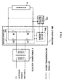
- FIG. 1 exemplarily shows the structure of the power transmission device according to this embodiment of the present invention.
- this power transmission device 1 is located between a generator 2 and a commercial electricity system 8.
- the power transmission device 1 comprises a DC ⁇ AC converter 3, an isolation transformer 4, a DC power source section 5, a transfer switch 6, and a commercial voltage monitor section 7.
- the generator 2 is a DC power source for generating a DC electric power (DC voltage).
- the generator 2 is composed of, for example, a solar battery.
- the DC ⁇ AC converter 3 converts a DC electric power generated by the generator 2 from DC to AC. As shown in FIG. 1, the DC ⁇ AC converter 3 is provided with an inverter circuit 100 and a voltage monitor circuit 101.
- the inverter circuit 100 comprises a bridge inverter 105 and an inverter control section 106 for controlling this bridge inverter 105.
- the bridge inverter 105 is composed of switching elements S1 to S4 each of which is provided with an electric current path and an control terminal (not shown).
- the switching elements S1 to S4 are composed of, for example, a field effect transistor.
- One end of the electric current path of the switching element S1 and one end of the electric current path of the switching element S3 are connected to one end of the generator 2.
- One end of the electric current path of the switching element S2 and one end of the electric current path of the switching element S4 are connected to the other end of the generator 2.
- the other end of the electric current path of the switching element S1 and the other end of the electric current path of the switching element S2 are connected to one end of a primary winding of the isolation transformer 4.
- the other end of the electric current path of the switching element S3 and the other end of the electric current path of the switching element S4 are connected to the other end of the primary winding of the isolation transformer 4.
- the switching elements S1 to S4 will be on or off according to a control signal applied to the control terminal of their own.
- the inverter control section 106 is driven by an electric power supplied by the generator 2.
- the inverter control section 106 controls the switching elements S1 to S4 constituting the bridge inverter 105, to be on or off.
- the inverter control section 106 controls the switching elements S1 to S4 by supplying each of the control terminals of the switching elements S1 to S4 with a control signal, so that the switching elements S2 and S3 may be off when the switching elements S1 and S4 are on, and the switching elements S1 and S4 may be off when the switching elements S2 and S3 are on.
- the switching elements S1 to S4 become on or off according to the aforementioned control conducted by the inverter control section 106.
- the bridge inverter 105 inverts a DC electric power supplied from the generator 2 from DC to AC.
- the voltage monitor circuit 101 determines whether or not a DC voltage applied by the generator 2 has reached a set level. And when determining that this DC voltage has reached the set level, the voltage monitor circuit 101 supplies the DC electric power output by the generator 2 to a power source of the inverter control section 106. The inverter circuit 100 is driven by the DC electric power supplied by the voltage monitor circuit 101.
- the isolation transformer has a primary winding and a secondary winding.
- the primary winding and the secondary winding are wound to a same iron core. And the primary winding and the secondary winding are isolated from each other.
- the primary winding is connected to the DC ⁇ AC converter 3.
- the secondary winding is connected to the DC power source section 5.
- An AC voltage applied by the DC ⁇ AC converter 3 is transformed according to a turn ratio of the primary winding against the secondary winding. This transformed AC voltage is output to the DC power source section 5.
- the DC power source section 5 transforms the AC voltage applied by the isolation transformer 4 into a DC voltage.
- the DC power source section 5 has a rectifier circuit 102.
- the rectifier circuit 102 is composed of diodes, a condenser, and the like, and is provided with a positive electrode and a negative electrode.
- the rectifier circuit 102 rectifies the AC voltage applied by the isolation transformer 4 by the diodes, and smoothes the rectified voltage by the condenser and the like and converts it to a DC voltage. This DC voltage is generated between the positive electrode and the negative electrode of the rectifier circuit 102 (the electric potential of the positive electrode is higher than that of the negative electrode.)
- the transfer switch 6 is driven by an electric power supplied from the commercial electricity system.
- the transfer switch 6 supplies or interrupts a supply of the rectified voltage which is to be supplied to the commercial electricity system from the rectifier circuit 102 according to a control signal transmitted form the commercial voltage monitor section 7.
- the commercial electricity system 8 is provided with a pair of output terminals for generating an AC voltage.
- the transfer switch 6 applies the rectified voltage to between the output terminals of the commercial electricity system 8 in such a way as that the rectified voltage is applied with the same polarity as this AC voltage provided.
- the commercial voltage monitor section 7 comprises a switch control circuit 103 and a half cycle monitor circuit 104.
- the switch control circuit 103 controls the transfer switch 6 by transmitting a control signal to the transfer switch 6.
- the switch control circuit 103 is driven by an electric power supplied from the commercial electricity system 8 (while an electric power is supplied from the DC power source section 5 to the commercial electricity system 8, this electric power also contributes to driving the switch control circuit 103).
- the switch control circuit 103 detects a voltage Vc of a commercial electricity generated by the commercial electricity system 8, and determines which of the detected voltage Vc and a predetermined voltage threshold levels +Vth and -Vth is higher or lower than the others. And the switch control circuit 103 controls the transfer switch 6 by transmitting a first control signal to the transfer switch 6 according to the determination result. (The level of +Vth is positive, and the level of -Vth is negative.)
- the half cycle monitor circuit 104 determines whether or not a length of a period of time in which the transfer switch 6 is on (a period of time in which the DC voltage is supplied from the DC power source section 5 to the commercial electricity system 8) is over a half of a length of a cycle of the voltage generated by the commercial electricity system 8. And the half cycle monitor circuit 104 supplies the transfer switch 6 with a second control signal when determining that the length of the period of time is over the half of the length of the cycle. As a result, the transfer switch 6 electrically cuts between the commercial electricity system 8 and the DC power source section 5.
- a generator 2 composed of a solar battery generates an electric power when the generator 2 is irradiated.
- the DC ⁇ AC converter 3 converts the electric power generated by the generator 2 from DC to AC when the electric power generated by the generator 2 is over a predetermined threshold level.
- the voltage converted to AC is transformed by the isolation transformer 4 (normally, it is boosted).
- the transformed AC voltage is converted from AC to DC by the DC power source section 5.
- the switch control circuit 103 transmits the first control signal showing which of the voltage Vc of the commercial electricity system 8 and the voltage threshold levels +Vth and ⁇ Vth is higher or lower than the others to the transfer switch 6.
- the DC voltage output by the DC power source section 5 is supplied or interrupted to be supplied to the commercial electricity system 8 with being provided with a polarity aforementioned as (1) or (3) by the transfer switch being switched.
- the transfer switch 6 is switched according to the first control signal supplied from the switch control circuit 103.
- FIG. 3 (a) is a graph showing a waveform of the AC voltage generated by the commercial electricity system 8, and the voltage threshold levels +Vth and - Vth.
- FIG. 3 (b) is a graph exemplarily showing continuity angles (periods of time in which the DC power source section 5 is electrically connected to the commercial electricity system 8), levels of the first control signal, and the relations.
- the switch control circuit 103 supplies the transfer switch 6 with the first control signal of the high level when determining that the voltage Vc of the commercial electricity system 8 is equal to or higher than the voltage threshold level +Vth of a positive polarity.
- the transfer switch 6 is switched in response to the first control signal of the high level so that the DC voltage may be supplied from the DC power source section 5 to the commercial electricity system 8 in a state of (1) aforementioned (the polarity of the voltage of the commercial electricity and the polarity of the DC voltage to be supplied will become the same).
- the switch control circuit 103 supplies the transfer switch 6 with the first control signal of the ground level when determining that the voltage Vc is lower than the voltage threshold level +Vth of a positive polarity, and higher than the voltage threshold level -Vth of a negative polarity.
- the period of time in which the transfer switch 6 is supplied with the first control signal of the ground level is the segment B to C and the segment D to A shown in FIG. 3 (a).
- the transfer switch 6 interrupts the supply of the DC voltage from the DC power source section 5 to the commercial electricity system 8 according to the first control signal of the ground level.
- the switch control circuit 103 supplies the transfer switch 6 with the first control signal of the low level when determining that the voltage Vc is equal to or lower than the voltage threshold level -Vth of a negative polarity (i.e., the polarity is negative and the absolute value of the voltage is equal to or higher than Vth).
- the transfer switch 6 supplies the commercial electricity system 8 with the DC voltage generated by the DC power source section 5 in a state of (3) aforementioned (i.e., in a state the polarity is reversed from the state of the above (1)).
- the polarity of the voltage of the commercial electricity and the polarity of the DC voltage to be supplied will become the same.
- this noise can be removed by using a filter composed of, for example, a coil and a condenser.
- the voltage monitor circuit 101 interrupts the supply of the electricity output by the generator 2 to the inverter control section 106 to stop the working of the inverter circuit 100. Accordingly, power transmission from the generator 2 to the commercial electricity system 8 stops.
- the switch control circuit 103 transmits the first control signal of the ground level to the transfer switch 6.
- the transfer switch 6 cuts between the commercial electricity system 8 and the DC power source section 5.
- the half cycle monitor circuit 104 detects that the period of time in which the transfer switch 6 is on becomes over the half of the cycle of the AC voltage generated by the commercial electricity system 8. The detection result is transmitted to the transfer switch 6 as the second control signal indicating the low level. The transfer switch 6 cuts between the commercial electricity system 8 and the DC power source section 5.
- the DC electric power generated by the DC power source section 5 is not supplied to devices connected to the commercial electricity system 8.
- the voltage monitor circuit 101 stops the working of the inverter circuit 100, or the commercial voltage monitor section 7 controls the transfer switch 6 to cut between the commercial electricity system 8 and the DC power source section 5. Accordingly, an electricity leakage can be prevented.
- the generator 2 and the commercial electricity system 8 are isolated by the isolation transformer 4 in regard to the power transmission device according to this embodiment of the present invention.
- the DC ⁇ AC converter 3 works by an electric power supplied by the generator 2.
- the commercial voltage monitor section 7 and the transfer switch 6 work by an electric power supplied by the commercial electricity system 8.
- This invention is not limited to the above embodiment.
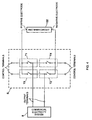
- the transfer switch 6 may be composed of switching elements T1 to T4 each of which is provided with an electric current passage and a control terminal, as shown in FIG. 4.
- the switching elements T1 to T4 may be composed of, for example, a field effect transistor.
- the electric current paths of the switching elements T1 to T4 may be composed of an electric current path of the field effect transistor which has the drain and source as both ends, and the control terminals of the switching elements T1 to T4 may be composed of the gates of the field effect transistors.
- One end of the electric current path of the switching element T1 and one end of the electric current path of the switching element T3 are connected to the positive electrode of the rectifier circuit 102.
- One end of the electric current passage of the switching element T2 and one end of the electric current passage of the switching element T4 are connected to the negative electrode of the rectifier circuit 102.
- the other end of the electric current path of the switching element T1 and the other end of the electric current path of the switching element T4 are connected to one of the output terminals of the commercial electricity system 8.
- the other end of the electric current path of the switching element T2 and the other end of the electric current path of the switching element T3 are connected to the other of the output terminals of the commercial electricity system 8.
- the switching elements T1 to T4 become on or off according to the control signal applied to the control terminal of their own.
- the transfer switch 6 has a structure shown in FIG. 4, by, for example, supplying the first control signal to the control terminal of the switching elements T1 to T4, the switch control circuit 103,
- the switching elements T1 to T4 become on or off according to the aforementioned control conducted by the switch control circuit 103.
- the half cycle monitor circuit 104 may determine whether or not the length of the period of time in which one of the switching elements T1 to T4 is on is over the length of the half of the cycle of the voltage generated by the commercial electricity system 8, and controls the transfer switch 6 so that all of the switching elements T1 to T4 may become off when determining that the length of the period of time is over the length of the half of the cycle. As a result, the transfer switch 6 electrically cuts between the commercial electricity system 8 and the DC power source section 5.
- the isolation transformer 4 may be composed of a magnetic leakage transformer having a large leakage reactance.
- the magnetic leakage transformer is characterized in that the leakage flux is increased to increase the leakage reactance when there is a rise in the amount of an electric current flowing through a winding. Because of this character, an increase in the amount of an electric current flowing through a secondary winding of the isolation transformer 4 is prevented, which prevents an over current in the secondary winding.
- the DC power source section 5 may comprise an overvoltage preventing circuit for preventing a rise in a DC voltage output from the rectifier circuit 102 when this DC voltage is excessively rising.
- the DC voltage output from the DC power source section 5 is prevented from rising excessively by this overvoltage preventing circuit.
- the DC power source section 5 may comprise a filter circuit for gentling the response of an electric current supplied from the DC power source section 5 to the commercial electricity system 8 when this electric current rises or falls. This filter circuit prevents a high-frequency noise from mixing into the commercial electricity system 8.
- a power transmission device and a method of transmitting power which are able to prevent an electricity from leaking from the generator to the commercial electricity system, and consequently to prevent an occurrence of a secondary damage.
- This invention is not limited to the above embodiments, but is variously changeable or applicative.
Landscapes
- Engineering & Computer Science (AREA)
- Power Engineering (AREA)
- Inverter Devices (AREA)
Applications Claiming Priority (3)
| Application Number | Priority Date | Filing Date | Title |
|---|---|---|---|
| JP14737499 | 1999-05-27 | ||
| JP14737499 | 1999-05-27 | ||
| PCT/JP2000/003424 WO2000074199A1 (fr) | 1999-05-27 | 2000-05-29 | Appareil de transmission d'energie et procede de transmission d'energie |
Publications (1)
| Publication Number | Publication Date |
|---|---|
| EP1102380A1 true EP1102380A1 (fr) | 2001-05-23 |
Family
ID=15428798
Family Applications (1)
| Application Number | Title | Priority Date | Filing Date |
|---|---|---|---|
| EP00931588A Withdrawn EP1102380A1 (fr) | 1999-05-27 | 2000-05-29 | Appareil de transmission d'energie et procede de transmission d'energie |
Country Status (5)
| Country | Link |
|---|---|
| US (1) | US6362985B1 (fr) |
| EP (1) | EP1102380A1 (fr) |
| JP (1) | JP3478338B2 (fr) |
| KR (1) | KR100419303B1 (fr) |
| WO (1) | WO2000074199A1 (fr) |
Cited By (2)
| Publication number | Priority date | Publication date | Assignee | Title |
|---|---|---|---|---|
| WO2004077637A1 (fr) * | 2003-02-20 | 2004-09-10 | Ebara Corporation | Appareil generateur d'electricite |
| CN102338833A (zh) * | 2011-06-03 | 2012-02-01 | 厦门科华恒盛股份有限公司 | 一种市电异常的快速检测方法及装置 |
Families Citing this family (8)
| Publication number | Priority date | Publication date | Assignee | Title |
|---|---|---|---|---|
| CN102255332A (zh) * | 2011-06-29 | 2011-11-23 | 黄俊嘉 | 并网逆变装置 |
| US20130158726A1 (en) | 2011-12-20 | 2013-06-20 | Kohler Co. | System and method for using a network to control multiple power management systems |
| US9281716B2 (en) | 2011-12-20 | 2016-03-08 | Kohler Co. | Generator controller configured for preventing automatic transfer switch from supplying power to the selected load |
| KR101373850B1 (ko) | 2014-02-07 | 2014-03-26 | 주식회사 네스앤텍 | 유선 비행체의 전원공급시스템 |
| JP6295782B2 (ja) * | 2014-03-31 | 2018-03-20 | 株式会社安川電機 | 電力変換装置、発電システム、制御装置および電力変換方法 |
| JP6305861B2 (ja) * | 2014-07-25 | 2018-04-04 | Ntn株式会社 | 送電装置 |
| EP3174189B1 (fr) | 2014-07-24 | 2020-09-16 | NTN Corporation | Dispositif de transmission de puissance |
| JP2020167747A (ja) * | 2017-07-31 | 2020-10-08 | 日本電産株式会社 | 電源装置、駆動装置、制御方法、及びプログラム |
Family Cites Families (8)
| Publication number | Priority date | Publication date | Assignee | Title |
|---|---|---|---|---|
| US3742330A (en) * | 1971-09-07 | 1973-06-26 | Delta Electronic Control Corp | Current mode d c to a c converters |
| JPS61214775A (ja) * | 1985-03-19 | 1986-09-24 | Mitsubishi Electric Corp | インバ−タの異常検出回路 |
| JPH07106065B2 (ja) * | 1986-11-14 | 1995-11-13 | 四国電力株式会社 | インバ−タ装置 |
| JP2918430B2 (ja) * | 1993-04-02 | 1999-07-12 | 三菱電機株式会社 | 電力変換装置 |
| JPH09107637A (ja) * | 1995-10-09 | 1997-04-22 | Hitachi Ltd | 太陽光発電システム |
| JPH09172784A (ja) * | 1995-12-19 | 1997-06-30 | Sharp Corp | 連系型インバータ装置 |
| JP3588917B2 (ja) * | 1996-06-19 | 2004-11-17 | ダイキン工業株式会社 | 電力変換装置 |
| JPH10207559A (ja) * | 1997-01-22 | 1998-08-07 | Sharp Corp | 連系形電力変換装置 |
-
2000
- 2000-05-29 JP JP2001500391A patent/JP3478338B2/ja not_active Expired - Fee Related
- 2000-05-29 US US09/744,863 patent/US6362985B1/en not_active Expired - Fee Related
- 2000-05-29 KR KR20017000809A patent/KR100419303B1/ko not_active IP Right Cessation
- 2000-05-29 WO PCT/JP2000/003424 patent/WO2000074199A1/fr not_active Application Discontinuation
- 2000-05-29 EP EP00931588A patent/EP1102380A1/fr not_active Withdrawn
Non-Patent Citations (1)
| Title |
|---|
| See references of WO0074199A1 * |
Cited By (2)
| Publication number | Priority date | Publication date | Assignee | Title |
|---|---|---|---|---|
| WO2004077637A1 (fr) * | 2003-02-20 | 2004-09-10 | Ebara Corporation | Appareil generateur d'electricite |
| CN102338833A (zh) * | 2011-06-03 | 2012-02-01 | 厦门科华恒盛股份有限公司 | 一种市电异常的快速检测方法及装置 |
Also Published As
| Publication number | Publication date |
|---|---|
| JP3478338B2 (ja) | 2003-12-15 |
| KR100419303B1 (ko) | 2004-02-21 |
| KR20010071977A (ko) | 2001-07-31 |
| WO2000074199A1 (fr) | 2000-12-07 |
| US6362985B1 (en) | 2002-03-26 |
Similar Documents
| Publication | Publication Date | Title |
|---|---|---|
| US6807072B2 (en) | Electric power conversion device with push-pull circuitry | |
| CN110879319B (zh) | 利用次级侧整流电压感测的电压和电流保护 | |
| US6072701A (en) | Current resonance type switching power source | |
| US5896280A (en) | Frequency converter and improved UPS employing the same | |
| US6362985B1 (en) | Power transmission apparatus and method for power transmission | |
| JP3519447B2 (ja) | スイッチ位置を監視する装置及び方法 | |
| US9537350B2 (en) | Switch-mode power supply with a dual primary transformer | |
| US10418906B2 (en) | High efficiency primary and secondary bias flyback converter with dual outputs | |
| US4591964A (en) | Method of securely interrupting the electric power supply from a low-frequency or direct voltage source to a load, and appartus for carrying out the method | |
| JP2008017650A (ja) | 電力変換装置 | |
| JP3346543B2 (ja) | スイッチング電源装置 | |
| US11075585B2 (en) | Synchronous rectification circuit and display device | |
| KR20060007919A (ko) | 스위칭 모드 전원공급장치를 위한 대기전력 절감 장치 | |
| JP2020174465A (ja) | 三相交流用の絶縁型力率改善装置 | |
| CA2356187A1 (fr) | Convertisseur indirect synchrone | |
| JP2000069747A (ja) | 電源装置 | |
| US5898580A (en) | Dc/dc converter with a protection circuit | |
| JPH0746841A (ja) | 直流電源装置 | |
| JP4304743B2 (ja) | 補助電源なしでオンオフ制御を可能にするスイッチング電源装置 | |
| KR100424891B1 (ko) | 2-선식 래치릴레이 상태 피드백회로 | |
| JP2712787B2 (ja) | インバータ直流入力電流の検出方法及び検出回路 | |
| JP2006158163A (ja) | スイッチング電源回路 | |
| RU95102587A (ru) | Источник вторичного электропитания | |
| JP2020137319A (ja) | スイッチング電源 | |
| CN116453905A (zh) | 接触器及其控制方法 |
Legal Events
| Date | Code | Title | Description |
|---|---|---|---|
| PUAI | Public reference made under article 153(3) epc to a published international application that has entered the european phase |
Free format text: ORIGINAL CODE: 0009012 |
|
| 17P | Request for examination filed |
Effective date: 20010124 |
|
| AK | Designated contracting states |
Kind code of ref document: A1 Designated state(s): AT BE CH CY DE DK ES FI FR GB GR IE IT LI LU MC NL PT SE |
|
| AX | Request for extension of the european patent |
Free format text: AL;LT;LV;MK;RO;SI |
|
| RBV | Designated contracting states (corrected) |
Designated state(s): DE FR GB |
|
| RAP1 | Party data changed (applicant data changed or rights of an application transferred) |
Owner name: SINANO ELECTRIC CO., LTD., Owner name: NTT DATA EX TECHNO CORORATION |
|
| RAP1 | Party data changed (applicant data changed or rights of an application transferred) |
Owner name: NTT DATA EX TECHNO CORPORATION Owner name: DAIICHI COMPONENTS, LTD |
|
| STAA | Information on the status of an ep patent application or granted ep patent |
Free format text: STATUS: THE APPLICATION HAS BEEN WITHDRAWN |
|
| 18W | Application withdrawn |
Effective date: 20071128 |