EP1101949B1 - Vorrichtung zur Steuerung eines hydraulischen Volumenstroms zumindest eines belasteten Arbeitsmittels - Google Patents
Vorrichtung zur Steuerung eines hydraulischen Volumenstroms zumindest eines belasteten Arbeitsmittels Download PDFInfo
- Publication number
- EP1101949B1 EP1101949B1 EP20000116754 EP00116754A EP1101949B1 EP 1101949 B1 EP1101949 B1 EP 1101949B1 EP 20000116754 EP20000116754 EP 20000116754 EP 00116754 A EP00116754 A EP 00116754A EP 1101949 B1 EP1101949 B1 EP 1101949B1
- Authority
- EP
- European Patent Office
- Prior art keywords
- valve body
- main
- control
- valve
- main valve
- Prior art date
- Legal status (The legal status is an assumption and is not a legal conclusion. Google has not performed a legal analysis and makes no representation as to the accuracy of the status listed.)
- Expired - Lifetime
Links
Images
Classifications
-
- F—MECHANICAL ENGINEERING; LIGHTING; HEATING; WEAPONS; BLASTING
- F15—FLUID-PRESSURE ACTUATORS; HYDRAULICS OR PNEUMATICS IN GENERAL
- F15B—SYSTEMS ACTING BY MEANS OF FLUIDS IN GENERAL; FLUID-PRESSURE ACTUATORS, e.g. SERVOMOTORS; DETAILS OF FLUID-PRESSURE SYSTEMS, NOT OTHERWISE PROVIDED FOR
- F15B13/00—Details of servomotor systems ; Valves for servomotor systems
- F15B13/01—Locking-valves or other detent i.e. load-holding devices
- F15B13/015—Locking-valves or other detent i.e. load-holding devices using an enclosed pilot flow valve
-
- F—MECHANICAL ENGINEERING; LIGHTING; HEATING; WEAPONS; BLASTING
- F15—FLUID-PRESSURE ACTUATORS; HYDRAULICS OR PNEUMATICS IN GENERAL
- F15B—SYSTEMS ACTING BY MEANS OF FLUIDS IN GENERAL; FLUID-PRESSURE ACTUATORS, e.g. SERVOMOTORS; DETAILS OF FLUID-PRESSURE SYSTEMS, NOT OTHERWISE PROVIDED FOR
- F15B13/00—Details of servomotor systems ; Valves for servomotor systems
- F15B2013/008—Throttling member profiles
Definitions
- the invention relates to a device for controlling a hydraulic volume flow of at least one loaded working fluid according to the preamble of claim 1.
- a generic device with a check valve in which a seat valve body is arranged.
- the poppet valve body cooperates with a housing-fixed main valve seat.
- a pilot valve body is arranged, which cooperates with a valve seat in the seat valve body.
- the poppet valve body is urged into the main valve seat by the action of pressure in a pressure space at one of its end faces.
- the pressure chamber is connected via a longitudinal bore and a radial throttle bore in the seat valve body with a working cylinder.
- the pressure in the pressure chamber and thus the position of the seat valve body in the check valve can be influenced by means of a proportional solenoid.
- the position of the seat valve body in the check valve determines a main volume flow from the working cylinder in a return line.
- a proportional pilot flow rate is established with the actuation stroke until the main valve body shifts in the opening direction and follows the pilot valve body. Due to the movement of the main valve body, a constant throttle cross-section is established between the pilot control valve body and the main valve body over the further actuating travel of the pilot control valve body. The volume flow from the cylinder thus remains constant regardless of the travel of the pilot valve body, until the cover of the main valve body is passed and flows through a fine control of the main valve body and the main valve seat, a main volume flow .. With open main valve seat turns in turn a total of the operating stroke of the pilot valve body proportional flow rate.
- the inventive solution is based on a device for controlling a hydraulic volume flow of at least one loaded working fluid with at least one check valve, which has a main valve body which cooperates with a main valve seat. Further, the check valve has an actuatable by an actuator pilot valve body, which cooperates with a pilot valve in the closing direction loading pressure in a arranged between the main valve body and an adjacent component valve pressure chamber, wherein in the closed position of the main valve body and the pilot valve body of the valve pressure chamber is connected to a working pressure chamber of the working fluid.
- a high closing speed can be achieved by pressure medium can be passed over a large cross section without intermediate throttle point in the valve pressure chamber when closing.
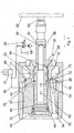
- FIG. 1 shows a device for controlling a volume flow 10 of a working cylinder 12, via which a load can be lifted by means of a pump 54 and a 3/2-way valve 56 and controlled by a check valve.
- the check valve has a main valve body 16 which cooperates with a main valve seat 17 and a main valve lift control 18.
- check valve ein.von a proportional solenoid 20 operable pilot valve body 24 which is arranged in a longitudinal bore 66 in the main valve body 16 and which cooperates with a pilot valve seat 26 and a the main valve body 16 in the closing direction 28 loading pressure in between the main valve body 16 and a valve insert 32 arranged valve pressure chamber 34 is controllable.
- the valve pressure chamber 34 is in the closed position of the main valve body 16 and the pilot valve body 24 via a longitudinal bore 62, via a first annular channel 70, via two further, connected to the first annular channel -70 annular channels 72, 74, via a radial bore 76 in the main valve body 16 and Connected via a channel 78 in the valve insert 32 with a working pressure chamber 48 of a working cylinder 12.
- the pilot valve body 24 leading longitudinal bore 66 is closed to the valve pressure chamber 34 with a plug 64.
- the pilot valve body 24 is pressed in the closing direction 28 in its pilot valve seat 26 in the main valve body 16 via a biased spring, not shown.
- a biased spring not shown.
- a arranged on the side facing away from the proportional solenoid 20 side of the pilot valve body 24 space 80 via a longitudinal bore 82 and via transverse bores 84, 86 in the pilot valve body 24 is christenttastet.
- the proportional solenoid 20 is activated.
- a magnetic ram 58 displaces the pilot valve body 24 against the spring.
- the pilot valve body 24 shifts from the pilot valve seat 26 in the main valve body 16 in the opening direction 60 and interrupts the connection between the working pressure chamber 48 and the valve pressure chamber 34 with a first control edge 50, which hydraulically separates the first annular channel 70 from the two further annular channels 72, 74.
- the pilot valve body 24 on its further actuation path via a second control edge 52 connects between the valve pressure chamber 34 via the pilot valve seat 26 with a return not shown.
- valve pressure chamber 34 is relieved via a pilot volume flow 36 and the main valve body 16 can move from its main valve seat 17 in the opening direction 60. Only when the main valve body 16 opens its main valve lift control 18, a proportional to the actuating travel of the pilot valve body 24 increasing volume flow from the working cylinder 12 flow into the return and a load can be lowered.
Landscapes
- Engineering & Computer Science (AREA)
- Physics & Mathematics (AREA)
- Fluid Mechanics (AREA)
- Mechanical Engineering (AREA)
- General Engineering & Computer Science (AREA)
- Fluid-Pressure Circuits (AREA)
- Check Valves (AREA)
- Servomotors (AREA)
Description
- Die Erfindung geht aus von einer Vorrichtung zur Steuerung eines hydraulischen Volumenstroms zumindest eines belasteten Arbeitsmittels nach dem Oberbegriff des Anspruchs 1.
- Aus der DE 41 40 604 A1 ist eine gattungsbildende Vorrichtung mit einem Sperrventil bekannt, in dem ein Sitzventilkörper angeordnet ist. Der Sitzventilkörper wirkt mit einem gehäusefesten Hauptventilsitz zusammen. Im Sitzventilkörper ist ein Vorsteuerventilkörper angeordnet, welcher mit einem Ventilsitz im Sitzventilkörper zusammenwirkt. Der Sitzventilkörper wird durch die Wirkung des Drucks in einem Druckraum an einer seiner Stirnseiten in den Hauptventilsitz gedrückt. Der Druckraum ist über eine Längsbohrung und über eine radiale Drosselbohrung im Sitzventilkörper mit einem Arbeitszylinder verbunden. Über eine variable Drosselstelle zwischen dem Vorsteuerventilkörper und dem Sitzventilkörper, deren Öffnungsquerschnitt durch den Vorsteuerventilkörper gesteuert wird, kann mit Hilfe eines Proportionalmagneten der Druck im Druckraum und damit die Lage des Sitzventilkörpers im Sperrventil beeinflußt werden. Die Lage des Sitzventilkörpers im Sperrventil bestimmt einen Hauptvolumenstrom vom Arbeitszylinder in eine Rücklaufleitung.
- Wird der Vorsteuerventilkörper vom Proportionalmagneten betätigt, stellt sich mit dem Betätigungshub ein proportionaler Vorsteuervolumenstrom ein, und zwar bis sich der Hauptventilkörper in Öffnungsrichtung verschiebt und dem Vorsteuerventilkörper folgt. Durch die Bewegung des Hauptventilkörpers stellt sich zwischen dem Vorsteuerventilkörper und dem Hauptventilkörper ein konstanter Drosselquerschnitt über dem weiteren Betätigungsweg des Vorsteuerventilkörpers ein. Der Volumenstrom aus dem Arbeitszylinder bleibt dadurch unabhängig vom Stellweg des Vorsteuerventilkörpers konstant, und zwar bis die Überdeckung des Hauptventilkörpers durchfahren ist und über eine Feinsteuerung des Hauptventilkörpers und über den Hauptventilsitz ein Hauptvolumenstrom abfließt..Bei geöffnetem Hauptventilsitz stellt sich insgesamt wiederum ein dem Betätigungshub des Vorsteuerventilkörpers proportionaler Volumenstrom ein.
- Es ist die Aufgabe der vorliegenden Erfindung eine Vorrichtung zum Steuern eines hydraulischen Volumenstroms anzugeben, die ein verbessertes Ansteuerverhalten aufweist.
- Die erfindungsgemäße Lösung geht aus von einer Vorrichtung zur Steuerung eines hydraulischen Volumenstroms zumindest eines belasteten Arbeitsmittels mit zumindest einem Sperrventil, das einen Hauptventilkörper aufweist, der mit einem Hauptventilsitz zusammenwirkt. Ferner besitzt das Sperrventil einen von einem Stellelement betätigbaren Vorsteuerventilkörper, der mit einem Vorsteuerventilsitz zusammenwirkt und über den ein den Hauptventilkörper in Schließrichtung belastender Druck in einem zwischen dem Hauptventilkörper und einem angrenzenden Bauteil angeordneten Ventildruckraum steuerbar ist, wobei in Schließstellung des Hauptventilkörpers und des Vorsteuerventilkörpers der Ventildruckraum mit einem Arbeitsdruckraum des Arbeitsmittels verbunden ist.
- Es wird vorgeschlagen, daß beim Verschieben des Vorsteuerventilkörpers aus dem Vorsteuerventilsitz der Vorsteuerventilkörper mit einer ersten Steuerkante die Verbindung zwischen dem Arbeitsdruckraum und dem Ventildruckraum unterbricht und anschließend über eine zweite Steuerkante den Ventildruckraum entlastet. Aus dem Arbeitsmittel fließt erst ein Volumenstrom in einen Rücklauf, wenn der Hauptventilkörper den Hauptventilsitz öffnet. Der Volumenstrom aus dem Arbeitsmittel steigt stets proportional zu dem Betätigungsweg des Vorsteuerventilkörpers an. Ein sich konstant einstellender Volumenstrom über einen durch Toleranzen nicht genau bestimmbaren Betätigungsweg des Vorsteuerventilkörpers kurz vor dem Öffnen des Hauptventilsitzes und Volumenstromschwankungen können vermieden und die Feinsteuerung kann verbessert werden.
- Ferner kann eine hohe Schließgeschwindigkeit erreicht werden, indem beim Schließen Druckmittel über einen großen Querschnitt ohne zwischengeschaltete Drosselstelle in den Ventildruckraum geleitet werden kann.
- Bis der Hauptventilkörper die Hauptventilfeinsteuerung öffnet und aus dem Arbeitsmittel ein Volumenstrom abfließen kann muß der Vorsteuerventilkörper einen Betätigungsweg zurücklegen, der vorzugsweise regelungstechnisch berücksichtigt ist, und zwar indem das Stellelement zu Beginn sprunghaft anspricht und den Vorsteuerventilkörper um einen Betätigungsweg verschiebt, der geringfügig kleiner ist als der Betätigungsweg, bei dem der Hauptventilkörper die Hauptventilfeinsteuerung öffnet.
- Weitere Vorteile ergeben sich aus der folgenden Zeichnungsbeschreibung. In der Zeichnung ist ein Ausführungsbeispiel der Erfindung dargestellt. Die Zeichnung, die Beschreibung und die Ansprüche enthalten zahlreiche Merkmale in Kombination. Der Fachmann wird die Merkmale zweckmäßigerweise auch einzeln betrachten und zu sinnvollen weiteren Kombinationen zusammenfassen.
-
- Fig.1 einen Ausschnitt einer erfindungsgemäßen Vorrichtung mit einem Sperrventil im Längsschnitt.
- Fig.1 zeigt eine Vorrichtung zur Steuerung eines Volumenstroms 10 eines Arbeitszylinders 12, über den mit einer Pumpe 54 und über ein 3/2-Wegeventil 56 eine Last gehoben und über ein Sperrventil gesteuert gesenkt werden kann. Das Sperrventil besitzt einen Hauptventilkörper 16, der mit einem Hauptventilsitz 17 und einer Hauptventilfeinsteuerung 18 zusammenwirkt.
- Ferner besitzt das Sperrventil einen.von einem Proportionalmagneten 20 betätigbaren Vorsteuerventilkörper 24, der in einer Längsbohrung 66 im Hauptventilkörper 16 angeordnet ist und der mit einem Vorsteuerventilsitz 26 zusammenwirkt und über den ein den Hauptventilkörper 16 in Schließrichtung 28 belastender Druck in einem zwischen dem Hauptventilkörper 16 und einem Ventileinsatz 32 angeordneten Ventildruckraum 34 steuerbar ist. Der Ventildruckraum 34 ist in der Schließstellung des Hauptventilkörpers 16 und des Vorsteuerventilkörpers 24 über eine Längsbohrung 62, über einen ersten Ringkanal 70, über zwei weitere, mit dem ersten Ringkanal -70 verbundene Ringkanäle 72, 74, über eine radiale Bohrung 76 im Hauptventilkörper 16 und über einen Kanal 78 im Ventileinsatz 32 mit einem Arbeitsdruckraum 48 eines Arbeitszylinders 12 verbunden. Die den Vorsteuerventilkörper 24 führende Längsbohrung 66 ist zum Ventildruckraum 34 mit einem Stopfen 64 verschlossen.
- Der Vorsteuerventilkörper 24 ist über eine nicht näher dargestellte vorgespannte Feder in Schließrichtung 28 in seinen Vorsteuerventilsitz 26 im Hauptventilkörper 16 gedrückt. Um zu vermeiden, daß der Vorsteuerventitkörper 24 gegen einen hydraulischen Druck verschoben werden muß, ist ein auf der dem Proportionalmagneten 20 abgewandten Seite des Vorsteuerventilkörpers 24 angeordneter Raum 80 über eine Längsbohrung 82 und über Querbohrungen 84, 86 im Vorsteuerventilkörper 24 druckenttastet.
- Soll eine Last mit dem Arbeitszylinder 12 abgesenkt werden, wird der Proportionalmagnet 20 aktiviert. Ein Magnetstößel 58 verschiebt den Vorsteuerventilkörper 24 gegen die Feder. Der Vorsteuerventilkörper 24 verschiebt sich aus dem Vorsteuerventilsitz 26 im Hauptventilkörper 16 in Öffnungsrichtung 60 und unterbricht die Verbindung zwischen dem Arbeitsdruckraum 48 und dem Ventildruckraum 34 mit einer ersten Steuerkante 50, die den ersten Ringkanal 70 von den zwei weiteren Ringkanälen 72, 74 hydraulisch trennt. Anschließend stellt der Vorsteuerventilkörper 24 auf seinem weiteren Betätigungsweg über eine zweite Steuerkante 52 eine Verbindung zwischen dem Ventildruckraum 34 über den Vorsteuerventilsitz 26 mit einem nicht näher dargestellten Rücklauf her. Der Ventildruckraum 34 wird über einen Vorsteuervolumenstrom 36 entlastet und der Hauptventilkörper 16 kann sich aus seinem Hauptventilsitz 17 in Öffnungsrichtung 60 verschieben. Erst wenn der Hauptventilkörper 16 seine Hauptventilfeinsteuerung 18 öffnet, kann ein mit dem Betätigungsweg des Vorsteuerventilkörpers 24 proportional ansteigender Volumenstrom aus dem Arbeitszylinder 12 in den Rücklauf abfließen und eine Last abgesenkt werden.
Claims (2)
- Vorrichtung zur Steuerung eines hydraulischen Volumenstroms (10) zumindest eines belasteten Arbeitsmittels (12) mit zumindest einem Sperrventil, das einen Hauptventilkörper (16) aufweist, der mit einer Hauptventilfeinsteuerung (18) zusammenwirkt, und mit einem von einem Stellelement (20) betätigbaren Vorsteuerventilkörper (24), der mit einem Vorsteuerventilsitz (26) zusammenwirkt und über den ein den Hauptventilkörper (16) in Schließrichtung (28) belastender Druck in einem zwischen dem Hauptventilkörper (16) und einem angrenzenden Bauteil (32) angeordneten Ventildruckraum (34) steuerbar ist, wobei in Schließstellung des Hauptventilkörpers (16) und des Vorsteuerventilkörpers (24) der Ventildruckraum (34) mit einem Arbeitsdruckraum (48) des Arbeitsmittels (12) verbunden ist,'
dadurch gekennzeichnet, daß
beim Verschieben des Vorsteuerventilkörpers (24) aus dem Vorsteuerventilsitz (26) der Vorsteuerventilkörper (24) mit einer ersten Steuerkante (50) die Verbindung zwischen dem Arbeitsdruckraum (48) und dem Ventildruckraum (34) unterbricht und anschließend über eine zweite Steuerkante (52) den Ventildruckraum (34) entlastet. - Vorrichtung nach Anspruch 1, dadurch gekennzeichnet, daß ein Betätigungsweg des Vorsteuerventilkörpers (24) bis zu einem Öffnen der Hauptventilfeinsteuerung (18) über den Hauptventilkörper (16) regelungstechnisch berücksichtigt ist.
Applications Claiming Priority (2)
| Application Number | Priority Date | Filing Date | Title |
|---|---|---|---|
| DE1999155521 DE19955521A1 (de) | 1999-11-18 | 1999-11-18 | Vorrichtung zur Steuerung eines hydraulischen Volumenstroms zumindest eines belasteten Arbeitsmittels |
| DE19955521 | 1999-11-18 |
Publications (3)
| Publication Number | Publication Date |
|---|---|
| EP1101949A2 EP1101949A2 (de) | 2001-05-23 |
| EP1101949A3 EP1101949A3 (de) | 2004-01-14 |
| EP1101949B1 true EP1101949B1 (de) | 2006-04-19 |
Family
ID=7929500
Family Applications (1)
| Application Number | Title | Priority Date | Filing Date |
|---|---|---|---|
| EP20000116754 Expired - Lifetime EP1101949B1 (de) | 1999-11-18 | 2000-08-03 | Vorrichtung zur Steuerung eines hydraulischen Volumenstroms zumindest eines belasteten Arbeitsmittels |
Country Status (2)
| Country | Link |
|---|---|
| EP (1) | EP1101949B1 (de) |
| DE (2) | DE19955521A1 (de) |
Families Citing this family (1)
| Publication number | Priority date | Publication date | Assignee | Title |
|---|---|---|---|---|
| CN106838101B (zh) * | 2017-03-24 | 2019-03-22 | 中国北方车辆研究所 | 油气悬挂闭锁阀 |
Family Cites Families (4)
| Publication number | Priority date | Publication date | Assignee | Title |
|---|---|---|---|---|
| CH671080A5 (de) * | 1986-10-01 | 1989-07-31 | Sulzer Ag | |
| DE4032078C2 (de) * | 1990-10-10 | 1997-08-07 | Bosch Gmbh Robert | Steuervorrichtung für einen hydraulischen Arbeitszylinder |
| DE4140604A1 (de) * | 1991-12-10 | 1993-06-17 | Bosch Gmbh Robert | Steuervorrichtung fuer den volumenstrom eines hydraulischen arbeitsmittels |
| US5799485A (en) * | 1995-06-22 | 1998-09-01 | Robert Bosch Gmbh | Electrohydraulic control device for double-acting consumer |
-
1999
- 1999-11-18 DE DE1999155521 patent/DE19955521A1/de not_active Withdrawn
-
2000
- 2000-08-03 DE DE50012599T patent/DE50012599D1/de not_active Expired - Lifetime
- 2000-08-03 EP EP20000116754 patent/EP1101949B1/de not_active Expired - Lifetime
Also Published As
| Publication number | Publication date |
|---|---|
| EP1101949A2 (de) | 2001-05-23 |
| DE50012599D1 (de) | 2006-05-24 |
| EP1101949A3 (de) | 2004-01-14 |
| DE19955521A1 (de) | 2001-05-23 |
Similar Documents
| Publication | Publication Date | Title |
|---|---|---|
| DE69819433T2 (de) | Elektromagnetisch betätigtes Steuerventil und hydraulisches Steuersystem unter Verwendung desselben | |
| DE19853355C1 (de) | Hydraulisch steuerbares Hubventil | |
| DE3805288C2 (de) | ||
| DE3705170C1 (de) | Hydraulische Steuervorrichtung | |
| EP0837275A1 (de) | Magnetbetätigtes Ablassventil eines elektrohydraulischen Hubmoduls | |
| DE2232857A1 (de) | Steuergeraet fuer hydraulische arbeitsgeraete | |
| DE2735559C2 (de) | Elektrohydraulisches Steuergerät für ein hydraulisch angetriebenes Arbeitsgerät | |
| EP0083688A2 (de) | Elektro-hydraulisch vorgesteuertes Proportionaldrosselventil | |
| DE4036564A1 (de) | Hydraulische einrichtung zur steuerung eines arbeitszylinders einer presse | |
| DE4237932C2 (de) | Volumenstromsteuerung für Kraftfahrzeughydraulik, insbesondere für Lenkeinrichtungen von Kraftfahrzeugen | |
| EP0110126B1 (de) | Elektromagnetisch betätigtes Wegeventil | |
| DE2816212C2 (de) | ||
| DE19729387A1 (de) | Prioritätsvariable Vorrichtung für ein Hydrauliksystem von Baugerät | |
| EP2767719B1 (de) | Ventil | |
| DE19632368A1 (de) | Elektrohydraulisches Regelwegeventil | |
| EP1611358B1 (de) | Stetig verstellbares wegeventil | |
| EP1875084B1 (de) | Wegeventil und damit ausgeführte ls-steueranordnung | |
| DE10138881A1 (de) | Verfahren zum Betreiben einer elektrohydraulischen Ventilsteuerung einer Brennkraftmaschine, Computerprogramm sowie Steuer- und Regelgerät zum Betreiben einer Brennkraftmaschine | |
| DE3048814C2 (de) | ||
| DE2929232C2 (de) | ||
| DE3519148C2 (de) | ||
| DE3714304A1 (de) | Ventilanordnung | |
| DE19955522A1 (de) | Vorrichtung zur Steuerung eines hydraulischen Volumenstroms | |
| EP0766009B1 (de) | Einrichtung zur Steuerung eines hydraulischen Motors | |
| EP1101949A2 (de) | Vorrichtung zur Steuerung eines hydraulischen Volumenstroms zumindest eines belasteten Arbeitsmittels |
Legal Events
| Date | Code | Title | Description |
|---|---|---|---|
| PUAI | Public reference made under article 153(3) epc to a published international application that has entered the european phase |
Free format text: ORIGINAL CODE: 0009012 |
|
| AK | Designated contracting states |
Kind code of ref document: A2 Designated state(s): AT BE CH CY DE DK ES FI FR GB GR IE IT LI LU MC NL PT SE |
|
| AX | Request for extension of the european patent |
Free format text: AL;LT;LV;MK;RO;SI |
|
| PUAL | Search report despatched |
Free format text: ORIGINAL CODE: 0009013 |
|
| AK | Designated contracting states |
Kind code of ref document: A3 Designated state(s): AT BE CH CY DE DK ES FI FR GB GR IE IT LI LU MC NL PT SE |
|
| AX | Request for extension of the european patent |
Extension state: AL LT LV MK RO SI |
|
| 17P | Request for examination filed |
Effective date: 20040714 |
|
| AKX | Designation fees paid |
Designated state(s): DE FR GB IT |
|
| 17Q | First examination report despatched |
Effective date: 20040825 |
|
| GRAP | Despatch of communication of intention to grant a patent |
Free format text: ORIGINAL CODE: EPIDOSNIGR1 |
|
| GRAS | Grant fee paid |
Free format text: ORIGINAL CODE: EPIDOSNIGR3 |
|
| GRAA | (expected) grant |
Free format text: ORIGINAL CODE: 0009210 |
|
| AK | Designated contracting states |
Kind code of ref document: B1 Designated state(s): DE FR GB IT |
|
| REG | Reference to a national code |
Ref country code: GB Ref legal event code: FG4D Free format text: NOT ENGLISH |
|
| REF | Corresponds to: |
Ref document number: 50012599 Country of ref document: DE Date of ref document: 20060524 Kind code of ref document: P |
|
| GBT | Gb: translation of ep patent filed (gb section 77(6)(a)/1977) |
Effective date: 20060814 |
|
| ET | Fr: translation filed | ||
| PLBE | No opposition filed within time limit |
Free format text: ORIGINAL CODE: 0009261 |
|
| STAA | Information on the status of an ep patent application or granted ep patent |
Free format text: STATUS: NO OPPOSITION FILED WITHIN TIME LIMIT |
|
| 26N | No opposition filed |
Effective date: 20070122 |
|
| PGFP | Annual fee paid to national office [announced via postgrant information from national office to epo] |
Ref country code: GB Payment date: 20110824 Year of fee payment: 12 |
|
| REG | Reference to a national code |
Ref country code: DE Ref legal event code: R084 Ref document number: 50012599 Country of ref document: DE Effective date: 20120211 |
|
| GBPC | Gb: european patent ceased through non-payment of renewal fee |
Effective date: 20120803 |
|
| PG25 | Lapsed in a contracting state [announced via postgrant information from national office to epo] |
Ref country code: GB Free format text: LAPSE BECAUSE OF NON-PAYMENT OF DUE FEES Effective date: 20120803 |
|
| REG | Reference to a national code |
Ref country code: FR Ref legal event code: PLFP Year of fee payment: 17 |
|
| PGFP | Annual fee paid to national office [announced via postgrant information from national office to epo] |
Ref country code: IT Payment date: 20160823 Year of fee payment: 17 |
|
| PGFP | Annual fee paid to national office [announced via postgrant information from national office to epo] |
Ref country code: FR Payment date: 20160825 Year of fee payment: 17 |
|
| PGFP | Annual fee paid to national office [announced via postgrant information from national office to epo] |
Ref country code: DE Payment date: 20161027 Year of fee payment: 17 |
|
| REG | Reference to a national code |
Ref country code: DE Ref legal event code: R119 Ref document number: 50012599 Country of ref document: DE |
|
| REG | Reference to a national code |
Ref country code: FR Ref legal event code: ST Effective date: 20180430 |
|
| PG25 | Lapsed in a contracting state [announced via postgrant information from national office to epo] |
Ref country code: DE Free format text: LAPSE BECAUSE OF NON-PAYMENT OF DUE FEES Effective date: 20180301 |
|
| PG25 | Lapsed in a contracting state [announced via postgrant information from national office to epo] |
Ref country code: IT Free format text: LAPSE BECAUSE OF NON-PAYMENT OF DUE FEES Effective date: 20170803 Ref country code: FR Free format text: LAPSE BECAUSE OF NON-PAYMENT OF DUE FEES Effective date: 20170831 |