EP1101923B1 - Kolben für Brennkraftmaschinen - Google Patents
Kolben für Brennkraftmaschinen Download PDFInfo
- Publication number
- EP1101923B1 EP1101923B1 EP20000123900 EP00123900A EP1101923B1 EP 1101923 B1 EP1101923 B1 EP 1101923B1 EP 20000123900 EP20000123900 EP 20000123900 EP 00123900 A EP00123900 A EP 00123900A EP 1101923 B1 EP1101923 B1 EP 1101923B1
- Authority
- EP
- European Patent Office
- Prior art keywords
- piston
- pin
- arrangement according
- oil
- ring
- Prior art date
- Legal status (The legal status is an assumption and is not a legal conclusion. Google has not performed a legal analysis and makes no representation as to the accuracy of the status listed.)
- Expired - Lifetime
Links
Images


Classifications
-
- F—MECHANICAL ENGINEERING; LIGHTING; HEATING; WEAPONS; BLASTING
- F16—ENGINEERING ELEMENTS AND UNITS; GENERAL MEASURES FOR PRODUCING AND MAINTAINING EFFECTIVE FUNCTIONING OF MACHINES OR INSTALLATIONS; THERMAL INSULATION IN GENERAL
- F16J—PISTONS; CYLINDERS; SEALINGS
- F16J1/00—Pistons; Trunk pistons; Plungers
- F16J1/10—Connection to driving members
- F16J1/14—Connection to driving members with connecting-rods, i.e. pivotal connections
- F16J1/16—Connection to driving members with connecting-rods, i.e. pivotal connections with gudgeon-pin; Gudgeon-pins
- F16J1/18—Securing of gudgeon-pins
-
- F—MECHANICAL ENGINEERING; LIGHTING; HEATING; WEAPONS; BLASTING
- F02—COMBUSTION ENGINES; HOT-GAS OR COMBUSTION-PRODUCT ENGINE PLANTS
- F02F—CYLINDERS, PISTONS OR CASINGS, FOR COMBUSTION ENGINES; ARRANGEMENTS OF SEALINGS IN COMBUSTION ENGINES
- F02F3/00—Pistons
Definitions
- the invention relates to a piston assembly according to the preamble of patent claim 1.
- Such a piston assembly is known from GB-A-356 612, in which two outwardly flared rings are arranged in each of the two grooves. The distance between the inner of the two rings and the bottom of the groove is completely filled by a disc. This arrangement is designed such that it forms a possible oil-tight connection. However, it has been found that in many applications, such a ⁇ labschottung is not appropriate, since it affects the lubrication of the bolt. Furthermore, the ends of the piston pin are completely in the pin bore, whereby bearing problems may occur during operation, which will be described in more detail below in connection with DE 44 38 703 A1.
- a piston is known in which the groove for the retaining ring is arranged in the pin bore.
- the ends of the piston pin are located completely in the pin bore, which can cause bearing problems during operation.
- FIG. 3 shows a vertical section through a piston 1 '
- the piston 1 ' has a combustion bowl 2, two grooves 3a, b for the piston rings and a groove 4 for the oil control ring in the region of the piston ring zone.
- a pin bore 5 ' is arranged, in which the piston pin 8 is mounted.
- a bearing bush (not shown) may be arranged in the bolt hole 5 'and a bearing bush (not shown) may be arranged in the bolt hole 5 'and a bearing bush (not shown) may be arranged.
- a groove 6 for receiving a pin securing ring 7 Adjacent to the outer end of the pin bore 5 ', a groove 6 for receiving a pin securing ring 7 is arranged, which secures the bolt 8 in the pin bore 5'.
- round Seeger rings or wire snap rings are used for this purpose.
- the bolt axis is identical to the eye axis 9. Under load during operation of the Piston 1 ', however, the bolt bends through 8, whereby the pin axis 10 shows the - exaggerated in the Fig. 3 - course.
- the deflection of the pin 8 causes the outer Bolzenlcante 11 digs into the bore 5 'and affects the flow of oil between the pin bore and the bolt. At the same time, the piston edge 12 digs from the top in the bolt 8, which also adversely affects the oil exchange and thus the lubrication of the bolt.
- This piston has the advantage that the bolt ends protrude outwards relative to the pin bore and thus the outer pin edge is exposed. An inevitably caused by the manufacturing process degree of the bolt outer edge thus can not affect the pin bearing. Another advantage of this arrangement is that the flexing bolt is no longer supported within the bearing and the hub break risk is reduced thereby. Characterized in that the groove for the pin locking ring is not arranged in the pin bore but in a preferably annular recess, a gap is formed between the inserted locking ring and the pin hole.
- the groove is arranged in the direction of the eye axis spaced from the pin bore, so that the gap can serve as an oil reservoir and thus further improves the oil lubrication in the bore.
- the length of the pin bore is less than or equal to its diameter.
- the load in the end region of the pin bore compared to the conventional pin holes is significantly reduced.
- each piston eye has at least one preferably vertical oil supply channel, which opens on the one hand into the pin bore and on the other hand is in communication with the groove for the oil control ring.
- the scraped off by the oil scraper oil thus passes directly into the pin bore, whereby a targeted improvement in oil lubrication is achieved.
- the oil supply channel is preferably connected via a horizontal connecting channel with this groove in connection.
- the connecting channel is aligned with the lower groove surface of the groove for the oil scraper ring.
- the oil supply channel is located opposite a preferably vertical oil outlet channel. While the ⁇ lzu Georgiakanal preferably opens from above into the pin bore, the ⁇ lauslwiekanal leads at the bottom of the bolt, the oil supplied from above down into the interior of the piston from. The oil introduced at each stroke movement from the oil scraper ring into the oil feed channel is thus removed in a simple manner.
- the piston pin is secured with an oval pin securing ring.
- a piston 1 with a combustion bowl 2, piston ring grooves 3a, b and a groove 4 for the oil scraper ring is shown.
- the piston eye 16 has a pin bore 5, which is arranged offset from the outer surface 17 of the piston 1. Between the outer surface 17 and the pin bore 5 a larger diameter annular groove 13 is arranged, so that the bolt 8 projects with its outer edge 11 in this space formed by the recess.
- the distance between the outer ends of the two bolt holes 5 of the piston 1 is shorter than the length of the bolt used.
- the outer edge 11 of the bolt 8 is thus exposed and can not dig into the bolt hole 5 under load, as is the case in the prior art.
- the length L of the pin bore is thereby reduced and, in the illustration shown here, is smaller than the diameter D of the pin bore 5.
- the groove 6 for the securing ring 7 is arranged in the annular recess 13, so that between the securing ring 7 and the pin bore 5, an annular clearance 20 is formed, in which an oil reservoir for the lubrication of the pin bore 5 can form.
- an oval snap ring may be provided which, due to the fact that it does not engage in the entire groove 6 (see Fig. 2), favors the flow of oil from the outside towards the pin hole 5.
- a vertical oil supply channel 14a is provided, which opens vertically from above into the pin bore 5 and communicates via a horizontal connecting channel 15 with the groove 4 for the oil scraper ring (not shown) in connection.
- the oil carried by the oil control ring into the groove 4 is thus directly supplied via the connecting channel 15 and the vertical oil supply channel 14a to the pin bore 5 and the pin 8, respectively, whereby the oil lubrication in this region is considerably improved.
- Opposite a ⁇ lablarbakanal 14 b is arranged in the Kolbenauge16, can flow through the excess oil in the region of the pin bore 5 in the interior 19 of the piston 1.
- the provision of an oil drainage channel 14b also offers the advantage that the introduction of the oil supply channel 14a is simplified in terms of manufacturing technology.
- FIG. 2 shows a side view of the piston 1 shown in FIG. 1. It can be clearly seen that the pin securing ring 7 has an oval shape and thus additional free spaces 21 between the pin securing ring 7 and the annular groove 13 for the passage of oil are present.
- the connection channel 15 is arranged so as to be aligned with the lower groove surface 18 of the groove 4, whereby the oil supply is improved.
Description
- Die Erfindung betrifft eine Kolbenanordnung gemäß dem Oberbegriff des Patentanspruchs 1.
- Eine derartige Kolbenanordnung ist aus der GB-A-356 612 bekannt, bei der in jeder der beiden Rillen zwei sich nach Außen erweiternde Ringe angeordnet sind. Der Abstand zwischen dem inneren der beiden Ringe und dem Grund des Einstichs wird durch eine Scheibe vollständig ausgefüllt. Diese Anordnung ist derart ausgeführt, daß sie eine möglichst öldichte Verbindung bildet. Es hat sich jedoch gezeigt, daß in vielen Anwendungsfällen eine derartige Ölabschottung nicht zweckmäßig ist, da sie die Schmierung des Bolzens beeinträchtigt. Des Weiteren befinden sich die Enden des Kolbenbolzens vollständig in der Bolzenbohrung, wodurch Lagerprobleme im Betrieb auftreten können, was nachfolgend im Zusammenhang mit der DE 44 38 703 A1 näher beschrieben wird.
- Aus der DE 44 38 703 A1 ist ein Kolben bekannt, bei dem die Rille für den Sicherungsring in der Bolzenbohrung angeordnet ist. Die Enden des Kolbenbolzens befinden sich vollständig in der Bolzenbohrung, wodurch Lagerprobleme im Betrieb auftreten können.
- Dieser Stand der Technik ist in der Fig. 3 beispielhaft dargestellt, die einen vertikalen Schnitt durch einen Kolben 1' zeigt
- Der Kolben 1' besitzt eine Brennraummulde 2, zwei Nuten 3a,b für die Kolbenringe und eine Nut 4 für den Ölabstreifring im Bereich der Kolbenringzone. Im Kolbenauge 16 ist eine Bolzenbohrung 5' angeordnet, in der der Kolbenbolzen 8 gelagert ist. Gegebenenfalls kann in der Bolzenbohrung 5' auch eine Lagerbuchse (nicht dargestellt) angeordnet sein.
- Benachbart zum außenliegenden Ende der Bolzenbohrung 5' ist eine Rille 6 zur Aufnahme eines Bolzensicherungsringes 7 angeordnet, der den Bolzen 8 in der Bolzenbohrung 5' sichert. Im allgemeinen werden hierfür runde Seeger-Ringe oder Drahtsprengringe eingesetzt. Im unbelasteten Zustand ist die Bolzenachse mit der Augenachse 9 identisch. Unter Belastung während des Betriebs des Kolbens 1' biegt sich allerdings der Bolzen 8 durch, wodurch die Bolzenachse 10 den - in der Fig. 3 übertrieben dargestellten - Verlauf zeigt.
- Die Durchbiegung des Bolzens 8 bewirkt, daß sich die äußere Bolzenlcante 11 in die Bohrung 5' eingräbt und den Ölfluß zwischen der Bolzenbohrung und dem Bolzen beeinträchtigt. Gleichzeitig gräbt sich auch die Kolbenkante 12 von der Oberseite in den Bolzen 8 ein, was ebenfalls den Ölaustausch und damit die Schmierung des Bolzens nachteilig beeinflußt.
- Um hier Abhilfe zu schaffen, wurde in der DE 42 10 056 A 1 vorgeschlagen, in den Nabenbohrungen parallel zur Augenachse verlaufende Schmiemuten anzuordnen, die in dem zwischen engerem oberen und weiterem unteren Abstand der Naben liegenden Stufenbereich zum Kurbelraum hin offen sind. Da auch bei diesem Kolben die Bolzenenden innerhalb der Bolzenbohrung angeordnet sind, werden die Verschleißprobleme noch nicht zufriedenstellend gelöst.
- Es ist daher Aufgabe der Erfindung, einen Kolben zu schaffen, der eine bezüglich Verschleiß und Ölschmierung verbesserte Bolzenlagerung aufweist.
- Diese Aufgabe wird mit einem Kolben gelöst, bei dem die Bolzenbohrung beidseitig jeweils unter Ausbildung eines durchmessergrößeren Einstichs gegenüber der Kolbenaußenfläche zurückversetzt ist und die Rillen für den Bolzensicherungsring in den Einstichen angeordnet sind.
- Dieser Kolben hat den Vorteil, daß die Bolzenenden gegenüber der Bolzenbohrung nach außen vorstehen und somit die äußere Bolzenkante freiliegt. Ein unweigerlich durch den Herstellungsprozeß bedingter Grad an der Bolzenaußenkante kann somit die Bolzenlagerung nicht beeinträchtigen. Ein weiterer Vorteil dieser Anordnung besteht darin, daß sich der durchbiegende Bolzen nicht mehr innerhalb der Lagerstelle abstützt und die Nabenbruchgefahr dadurch verringert wird. Dadurch, daß die Rille für den Bolzensicherungsring nicht in der Bolzenbohrung sondern in einem vorzugsweise ringförmigen Einstich angeordnet ist, wird zwischen dem eingesetzten Sicherungsring und der Bolzenbohrung ein Zwischenraum gebildet.
- Vorzugsweise ist die Rille in Richtung der Augenachse beabstandet zur Bolzenbohrung angeordnet, so daß der Zwischenraum als Ölreservoir dienen kann und somit die Ölschmierung im Bereich der Bohrung zusätzlich verbessert.
- Vorteilhafterweise ist die Länge der Bolzenbohrung kleiner gleich ihrem Durchmesser. Dadurch wird die Belastung im Endbereich der Bolzenbohrung gegenüber den herkömmlichen Bolzenbohrungen erheblich vermindert.
- Die Schmierung im Bereich der Bolzenbohrung kann weiterhin dadurch verbessert werden, daß jedes Kolbenauge mindestens einen vorzugsweise vertikalen Ölzuführkanal aufweist, der einerseits in die Bolzenbohrung mündet und andererseits mit der Nut für den Ölabstreifring in Verbindung steht. Das vom Ölabstreifring abgestreifte Öl gelangt somit unmittelbar in die Bolzenbohrung, wodurch eine gezielte Verbesserung der Ölschmierung erzielt wird.
- Der Ölzuführungskanal steht vorzugsweise über einen horizontalen Verbindungskanal mit dieser Nut in Verbindung. Vorzugsweise fluchtet der Verbindungskanal mit der unteren Nutfläche der Nut für den Ölabstreifring. Durch diese Maßnahme wird der Ölfluß in die Bolzenbohrung erleichtert.
- Vorteilhafterweise liegt dem Ölzuführungskanal ein vorzugsweise vertikaler Ölauslaßkanal gegenüber. Während der Ölzuführkanal vorzugsweise von oben in die Bolzenbohrung mündet, führt der Ölauslaßkanal an der Unterseite des Bolzens das von oben zugeführte Öl nach unten in den Innenraum des Kolbens ab. Das bei jeder Hubbewegung vom Ölabstreifring in den Ölzuführkanal eingeleitere Öl wird somit auf einfache Weise abgeführt.
- Vorzugsweise ist der Kolbenbolzen mit einem ovalen Bolzensicherungsring gesichert.
- Beispielhafte Ausführungsformen der Erfindung werden nachfolgend anhand der Zeichnungen erläutert.
- Es zeigen:
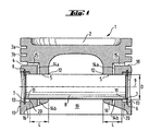
- Fig. 1
- einen Vertikalschnitt durch einen erfindungsgemäßen Kolben,
- Fig. 2
- die Seitenansicht des in Fig. 1 gezeigten Kolbens,
- Fig. 3
- einen Vertikalschnitt durch einen Kolben gemäß des Standes der Technik.
- In der Fig. 1 ist ein Kolben 1 mit einer Brennraummulde 2, Kolbenringnuten 3a,b sowie einer Nut 4 für den Ölabstreifring dargestellt. Das Kolbenauge 16 weist eine Bolzenbohrung 5 auf, die gegenüber der Außenfläche 17 des Kolbens 1 zurückversetzt angeordnet ist. Zwischen der Außenfläche 17 und der Bolzenbohrung 5 ist ein durchmessergrößerer ringförmiger Einstich 13 angeordnet, so daß der Bolzen 8 mit seiner Außenkante 11 in diesen durch den Einstich gebildeten Freiraum vorsteht. Der Abstand der äußeren Enden der beiden Bolzenbohrungen 5 des Kolbens 1 ist kürzer als die Länge des eingesetzten Bolzens. Die Außenkante 11 des Bolzens 8 liegt somit frei und kann sich unter Belastung nicht in die Bolzenbohrung 5 eingraben, wie dies beim Stand der Technik der Fall ist. Die Länge L der Bolzenbohrung wird dadurch verringert werden und ist in der hier gezeigten Darstellung kleiner als der Durchmesser D der Bolzenbohrung 5.
- Die Rille 6 für den Sicherungsring 7 ist in dem ringförmigen Einstich 13, angeordnet, so daß zwischen dem Sicherungsring 7 und der Bolzenbohrung 5 ein ringförmiger Freiraum 20 gebildet wird, in dem sich ein Ölreservoir für die Schmierung der Bolzenbohrung 5 bilden kann.
- Als Bolzensicherungsring 7 kann ein ovaler Sprengring vorgesehen sein, der aufgrund der Tatsache, daß er nicht in die gesamte Rille 6 eingreift (s. Fig. 2), den Ölfluß von außen in Richtung Bolzenbohrung 5 begünstigt.
- Zusätzlich ist ein vertikaler Ölzuführungskanal 14a vorgesehen, der vertikal von oben in die Bolzenbohrung 5 mündet und über einen horizontalen Verbindungskanal 15 mit der Nut 4 für den Ölabstreifring (nicht dargestellt) in Verbindung steht. Das vom Ölabstreifring in die Nut 4 beförderte Öl wird somit über den Verbindungskanal 15 und den vertikalen Ölzuführungskanal 14a unmittelbar der Bolzenbohrung 5 bzw. dem Bolzen 8 zugeführt, wodurch die Ölschmierung in diesem Bereich erheblich verbessert wird.
- Gegenüberliegend ist im Kolbenauge16 ein Ölablaßkanal 14b angeordnet, durch den überschüssiges Öl im Bereich der Bolzenbohrung 5 in den Innenraum 19 des Kolbens 1 abfließen kann. Das Vorsehen eines Ölablaßkanals 14b bietet auch den Vorteil, daß das Einbringen des Ölzuführungskanals 14a herstellungstechnisch vereinfacht wird.
- In der Fig. 2 ist eine Seitenansicht des in Fig. 1 gezeigten Kolbens 1 dargestellt. Es ist deutlich zu sehen, daß der Bolzensicherungsring 7 eine ovale Form aufweist und somit zusätzliche Freiräume 21 zwischen dem Bolzensicherungsring 7 und dem ringförmigen Einstich 13 zum Durchtritt von Öl vorhanden sind. Der Verbindungskanal 15 ist derart angeordnet, daß er mit der unteren Nutfläche 18 der Nut 4 fluchtet, wodurch die Ölzuführung verbessert wird.
-
- 1
- Kolben
- 1'
- Kolben
- 2
- Brennraummulde
- 3a,b
- Ringnut
- 4
- Ringnut für Ölabstreifring
- 5
- Bolzenbohrung
- 5'
- Bolzenbohrung
- 6
- Rille für Sicherungsring
- 7
- Bolzensicherungsring
- 7'
- Bolzensicherungsring
- 8
- Kolbenbolzen
- 9
- Augenachse
- 10
- Kolbenachse unter Belastung
- 11
- Bolzenkante
- 12
- Kolbenkante
- 13
- ringförmiger Einstich
- 14a
- vertikaler Zuführkanal
- 14b
- Ölablaßkanal
- 15
- horizontaler Verbindungskanal
- 16
- Kolbenauge
- 17
- Kolbenaußenfläche
- 18
- untere Nutfläche
- 19
- Innenraum
- 20
- ringförmiger Freiraum
- 21
- Freiraum
Claims (9)
- Kolbenanordnung für Brennkraftmaschinen mit zwei Bolzenbohrungen (5), in denen ein Kolbenbolzen (8) gelagert ist, wobei die Bolzenbohrungen (5) zwei Rillen (6) für jeweils einen Bolzensicherungsring (7) sowie Ringnuten (3a, 3b, 4) in der Kolbenringzone für Kolbenringe und Ölabstreifring aufweist und wobei die Bolzenbohrung (5) beiderseits jeweils unter Ausbildung eines durchmessergrößeren Einstichs (13) gegenüber der Kolbenaußenfläche (17) zurückversetzt ist und die Rillen (6) für den Bolzensicherungsring (7) in den Einstichen (13) angeordnet sind, dadurch gekennzeichnet, dass der Kolbenbolzen (8) beiderseits gegenüber den Bolzenbohrungen (5) nach außen vorsteht, so dass die äußeren Bolzenkanten frei liegen.
- Kolbenanordnung nach Anspruch 1, dadurch gekennzeichnet, dass der Einstich (13) ringförmig ist.
- Kolbenanordnung nach Anspruch 1 oder 2, dadurch gekennzeichnet, dass die Rille (6) in Richtung der Augenachse (9) beabstandet zur Bolzenbohrung (5) angeordnet ist.
- Kolbenanordnung nach einem der Ansprüche 1 bis 3, dadurch gekennzeichnet, dass die Länge L der Bolzenbohrung (5) kleiner gleich ihres Durchmessers D ist.
- Kolbenanordnung nach einem der Ansprüche 1 bis 4, dadurch gekennzeichnet, dass jedes Kolbenauge (16) mindestens einen Ölzuführkanal (14a) aufweist, der einerseits in die Kolbenbohrung (5) mündet und andererseits mit der Nut (4) für den Ölabstreifring in Verbindung steht.
- Kolbenanordnung nach Anspruch 5, dadurch gekennzeichnet, dass der Ölzufuhrkanal (14a) über einen horizontalen Verbindungskanal (15) mit der Nut (4) in Verbindung steht.
- Kolbenanordnung nach einem der Ansprüche 1 bis 6, dadurch gekennzeichnet, dass der Verbindungskanal (15) mit der unteren Nutfläche (18) der Nut (4) fluchtet
- Kolbenanordnung nach einem der Ansprüche 1 bis 6, dadurch gekennzeichnet, dass dem vertikalen Ölzuführungskanal (14a) ein vertikaler Ölauslaßkanal (14b) gegenübersteht.
- Kolbenanordnung nach einem der Ansprüche 1 bis 8, dadurch gekennzeichnet, dass der Kolbenbolzen (8) mit ovalen Bolzensicherungsringen (7) gesichert ist
Applications Claiming Priority (2)
| Application Number | Priority Date | Filing Date | Title |
|---|---|---|---|
| DE19955197 | 1999-11-16 | ||
| DE1999155197 DE19955197C2 (de) | 1999-11-16 | 1999-11-16 | Kolben für Brennkraftmaschinen |
Publications (3)
| Publication Number | Publication Date |
|---|---|
| EP1101923A2 EP1101923A2 (de) | 2001-05-23 |
| EP1101923A3 EP1101923A3 (de) | 2002-02-06 |
| EP1101923B1 true EP1101923B1 (de) | 2006-01-04 |
Family
ID=7929282
Family Applications (1)
| Application Number | Title | Priority Date | Filing Date |
|---|---|---|---|
| EP20000123900 Expired - Lifetime EP1101923B1 (de) | 1999-11-16 | 2000-11-03 | Kolben für Brennkraftmaschinen |
Country Status (2)
| Country | Link |
|---|---|
| EP (1) | EP1101923B1 (de) |
| DE (2) | DE19955197C2 (de) |
Families Citing this family (3)
| Publication number | Priority date | Publication date | Assignee | Title |
|---|---|---|---|---|
| DE10255732A1 (de) | 2002-11-29 | 2004-06-09 | Mahle Gmbh | Bolzennabe eines Kolbens für einen Verbrennungsmotor |
| FR2927666A3 (fr) * | 2008-02-15 | 2009-08-21 | Renault Sas | Piston pour moteur a combustion. |
| DE102019211336B4 (de) * | 2019-07-30 | 2023-02-02 | Federal-Mogul Nürnberg GmbH | Kolben mit Sicherungsringnut in der Bolzenbohrung für einen Verbrennungsmotor |
Family Cites Families (11)
| Publication number | Priority date | Publication date | Assignee | Title |
|---|---|---|---|---|
| GB356612A (en) * | 1930-12-31 | 1931-09-10 | Thomas Craig English | Improvements in trunk pistons |
| GB757226A (en) * | 1953-11-17 | 1956-09-19 | Bristol Pneumatic Tools Ltd | Improved means for mounting a gudgeon pin in a piston |
| FR1300937A (fr) * | 1961-06-30 | 1962-08-10 | Axe élastique pour piston | |
| US3494262A (en) * | 1967-08-09 | 1970-02-10 | Trw Inc | Piston |
| US3515035A (en) * | 1968-07-05 | 1970-06-02 | Brunswick Corp | Piston pin lubrication |
| JPH063263B2 (ja) * | 1986-07-07 | 1994-01-12 | 日本特殊陶業株式会社 | ピストンピンとスナツプリングとの潤滑機構 |
| US4796517A (en) * | 1986-07-08 | 1989-01-10 | Ngk Spark Plug Co., Ltd. | Metal piston and ceramic piston pin assembly |
| DE8815283U1 (de) * | 1988-12-08 | 1989-02-16 | Scheufler, Roland, 7107 Neckarsulm, De | |
| DE4210056A1 (de) * | 1992-03-27 | 1993-09-30 | Mahle Gmbh | Hubkolben eines Verbrennungsmotors |
| DE4438703C2 (de) * | 1994-10-29 | 2003-12-18 | Mahle Gmbh | Leichtmetallkolben mit Kühlkanal für Verbrennungsmotoren |
| US5694829A (en) * | 1995-04-25 | 1997-12-09 | Yamaha Hatsudoki Kabushiki Kaisha | Piston and piston pin arrangement for reciprocating machine |
-
1999
- 1999-11-16 DE DE1999155197 patent/DE19955197C2/de not_active Expired - Lifetime
-
2000
- 2000-11-03 DE DE50012012T patent/DE50012012D1/de not_active Expired - Fee Related
- 2000-11-03 EP EP20000123900 patent/EP1101923B1/de not_active Expired - Lifetime
Also Published As
| Publication number | Publication date |
|---|---|
| DE19955197A1 (de) | 2001-05-23 |
| EP1101923A3 (de) | 2002-02-06 |
| EP1101923A2 (de) | 2001-05-23 |
| DE19955197C2 (de) | 2003-09-18 |
| DE50012012D1 (de) | 2006-03-30 |
Similar Documents
| Publication | Publication Date | Title |
|---|---|---|
| DE3929486C2 (de) | Kaltgeformter Schwinghebel | |
| DE4133033C2 (de) | Schwinghebel | |
| DE4336360C2 (de) | Kipphebel zur Betätigung von zwei Ventilen | |
| DE19828847B4 (de) | Kolbenbolzenbuchse | |
| EP1521929B1 (de) | Kolben für einen verbrennungsmotor | |
| DE102004048939A1 (de) | Pleuelstange mit Schmiermittelrohr | |
| EP2841722B1 (de) | Nockenwelle mit durch drucköl beölbare, verstellbare nocken | |
| DE4309776C2 (de) | Kolben für Brennkraftmaschinen | |
| WO2016066599A1 (de) | Kühlkanalabdeckung sowie mit einer kühlkanalabdeckung versehener kolben | |
| DE3534536C2 (de) | ||
| DE10300514A1 (de) | Durchflußwegstruktur eines Hohlrohrs | |
| WO2012116687A1 (de) | Kolben für einen verbrennungsmotor | |
| EP2236800A1 (de) | Zylinder mit Mitteln zur Verteilung von Schmiermittel | |
| EP0643244B1 (de) | Ventil | |
| EP1999360A1 (de) | Kolben für einen verbrennungsmotor | |
| EP1101923B1 (de) | Kolben für Brennkraftmaschinen | |
| EP3762638B1 (de) | Plattenventil sowie verfahren zum betrieb desselben | |
| DE8102660U1 (de) | Flachdichtung, insbesondere Zylinderkopfdichtung für Verbrennungskraftmaschinen | |
| DE102018117198B4 (de) | Mehrteiliger Ölabstreif-Kolbenring mit verringerter Reibung | |
| WO2020011767A1 (de) | Kolben für einen verbrennungsmotor | |
| DE19944668A1 (de) | Vorrichtung zur Veränderung der Verdichtung einer Hubkolbenbrennkraftmaschine | |
| EP2090757B1 (de) | Kipphebelanordnung mit einer Nuten aufweisenden Lagerschale | |
| DE102009018981A1 (de) | Kolben für eine Hubkolbenmaschine | |
| DE60018029T2 (de) | Hydraulisches Spielausgleichselement | |
| DE602004007424T2 (de) | Lagerstruktur einer Nockenwelle |
Legal Events
| Date | Code | Title | Description |
|---|---|---|---|
| PUAI | Public reference made under article 153(3) epc to a published international application that has entered the european phase |
Free format text: ORIGINAL CODE: 0009012 |
|
| AK | Designated contracting states |
Kind code of ref document: A2 Designated state(s): DE FR GB IT SE Kind code of ref document: A2 Designated state(s): AT BE CH CY DE DK ES FI FR GB GR IE IT LI LU MC NL PT SE TR |
|
| AX | Request for extension of the european patent |
Free format text: AL;LT;LV;MK;RO;SI |
|
| PUAL | Search report despatched |
Free format text: ORIGINAL CODE: 0009013 |
|
| AK | Designated contracting states |
Kind code of ref document: A3 Designated state(s): AT BE CH CY DE DK ES FI FR GB GR IE IT LI LU MC NL PT SE TR |
|
| AX | Request for extension of the european patent |
Free format text: AL;LT;LV;MK;RO;SI |
|
| RIC1 | Information provided on ipc code assigned before grant |
Free format text: 7F 02F 3/00 A, 7F 16J 1/18 B, 7F 16J 1/08 B |
|
| 17P | Request for examination filed |
Effective date: 20020130 |
|
| AKX | Designation fees paid |
Free format text: DE FR GB IT SE |
|
| 17Q | First examination report despatched |
Effective date: 20041125 |
|
| GRAP | Despatch of communication of intention to grant a patent |
Free format text: ORIGINAL CODE: EPIDOSNIGR1 |
|
| RIN1 | Information on inventor provided before grant (corrected) |
Inventor name: HOPPE-BOEKEN, PETER-CLEMENS |
|
| GRAS | Grant fee paid |
Free format text: ORIGINAL CODE: EPIDOSNIGR3 |
|
| GRAA | (expected) grant |
Free format text: ORIGINAL CODE: 0009210 |
|
| AK | Designated contracting states |
Kind code of ref document: B1 Designated state(s): DE FR GB IT SE |
|
| PG25 | Lapsed in a contracting state [announced via postgrant information from national office to epo] |
Ref country code: IT Free format text: LAPSE BECAUSE OF FAILURE TO SUBMIT A TRANSLATION OF THE DESCRIPTION OR TO PAY THE FEE WITHIN THE PRESCRIBED TIME-LIMIT;WARNING: LAPSES OF ITALIAN PATENTS WITH EFFECTIVE DATE BEFORE 2007 MAY HAVE OCCURRED AT ANY TIME BEFORE 2007. THE CORRECT EFFECTIVE DATE MAY BE DIFFERENT FROM THE ONE RECORDED. Effective date: 20060104 |
|
| REG | Reference to a national code |
Ref country code: GB Ref legal event code: FG4D Free format text: NOT ENGLISH |
|
| REG | Reference to a national code |
Ref country code: SE Ref legal event code: TRGR |
|
| REF | Corresponds to: |
Ref document number: 50012012 Country of ref document: DE Date of ref document: 20060330 Kind code of ref document: P |
|
| GBT | Gb: translation of ep patent filed (gb section 77(6)(a)/1977) |
Effective date: 20060309 |
|
| ET | Fr: translation filed | ||
| RAP2 | Party data changed (patent owner data changed or rights of a patent transferred) |
Owner name: FEDERAL-MOGUL WIESBADEN GMBH |
|
| PLBE | No opposition filed within time limit |
Free format text: ORIGINAL CODE: 0009261 |
|
| STAA | Information on the status of an ep patent application or granted ep patent |
Free format text: STATUS: NO OPPOSITION FILED WITHIN TIME LIMIT |
|
| 26N | No opposition filed |
Effective date: 20061005 |
|
| PGFP | Annual fee paid to national office [announced via postgrant information from national office to epo] |
Ref country code: IT Payment date: 20081124 Year of fee payment: 9 Ref country code: SE Payment date: 20081107 Year of fee payment: 9 |
|
| PGFP | Annual fee paid to national office [announced via postgrant information from national office to epo] |
Ref country code: FR Payment date: 20081106 Year of fee payment: 9 |
|
| PGFP | Annual fee paid to national office [announced via postgrant information from national office to epo] |
Ref country code: DE Payment date: 20081128 Year of fee payment: 9 |
|
| PGFP | Annual fee paid to national office [announced via postgrant information from national office to epo] |
Ref country code: GB Payment date: 20081008 Year of fee payment: 9 |
|
| EUG | Se: european patent has lapsed | ||
| GBPC | Gb: european patent ceased through non-payment of renewal fee |
Effective date: 20091103 |
|
| REG | Reference to a national code |
Ref country code: FR Ref legal event code: ST Effective date: 20100730 |
|
| PG25 | Lapsed in a contracting state [announced via postgrant information from national office to epo] |
Ref country code: FR Free format text: LAPSE BECAUSE OF NON-PAYMENT OF DUE FEES Effective date: 20091130 |
|
| PG25 | Lapsed in a contracting state [announced via postgrant information from national office to epo] |
Ref country code: DE Free format text: LAPSE BECAUSE OF NON-PAYMENT OF DUE FEES Effective date: 20100601 |
|
| PG25 | Lapsed in a contracting state [announced via postgrant information from national office to epo] |
Ref country code: GB Free format text: LAPSE BECAUSE OF NON-PAYMENT OF DUE FEES Effective date: 20091103 |
|
| PG25 | Lapsed in a contracting state [announced via postgrant information from national office to epo] |
Ref country code: IT Free format text: LAPSE BECAUSE OF NON-PAYMENT OF DUE FEES Effective date: 20091103 |
|
| PG25 | Lapsed in a contracting state [announced via postgrant information from national office to epo] |
Ref country code: SE Free format text: LAPSE BECAUSE OF NON-PAYMENT OF DUE FEES Effective date: 20091104 |