EP1101923A2 - Kolben für Brennkraftmaschinen - Google Patents
Kolben für Brennkraftmaschinen Download PDFInfo
- Publication number
- EP1101923A2 EP1101923A2 EP00123900A EP00123900A EP1101923A2 EP 1101923 A2 EP1101923 A2 EP 1101923A2 EP 00123900 A EP00123900 A EP 00123900A EP 00123900 A EP00123900 A EP 00123900A EP 1101923 A2 EP1101923 A2 EP 1101923A2
- Authority
- EP
- European Patent Office
- Prior art keywords
- piston
- pin
- ring
- groove
- bolt
- Prior art date
- Legal status (The legal status is an assumption and is not a legal conclusion. Google has not performed a legal analysis and makes no representation as to the accuracy of the status listed.)
- Granted
Links
Images


Classifications
-
- F—MECHANICAL ENGINEERING; LIGHTING; HEATING; WEAPONS; BLASTING
- F16—ENGINEERING ELEMENTS AND UNITS; GENERAL MEASURES FOR PRODUCING AND MAINTAINING EFFECTIVE FUNCTIONING OF MACHINES OR INSTALLATIONS; THERMAL INSULATION IN GENERAL
- F16J—PISTONS; CYLINDERS; SEALINGS
- F16J1/00—Pistons; Trunk pistons; Plungers
- F16J1/10—Connection to driving members
- F16J1/14—Connection to driving members with connecting-rods, i.e. pivotal connections
- F16J1/16—Connection to driving members with connecting-rods, i.e. pivotal connections with gudgeon-pin; Gudgeon-pins
- F16J1/18—Securing of gudgeon-pins
-
- F—MECHANICAL ENGINEERING; LIGHTING; HEATING; WEAPONS; BLASTING
- F02—COMBUSTION ENGINES; HOT-GAS OR COMBUSTION-PRODUCT ENGINE PLANTS
- F02F—CYLINDERS, PISTONS OR CASINGS, FOR COMBUSTION ENGINES; ARRANGEMENTS OF SEALINGS IN COMBUSTION ENGINES
- F02F3/00—Pistons
Definitions
- the invention relates to a piston for internal combustion engines with two Pin bores for the bearing of a piston pin, with two grooves for one pin retaining ring each and ring grooves in the piston ring zone for piston rings and oil control ring.
- Such a piston is known for example from DE 44 38 703 A1, wherein the groove for the locking ring is arranged in the bolt hole. The ends of the piston pin are completely in the pin bore, which can cause storage problems in operation.
- FIG. 3 shows a vertical section through a piston 1 '
- the piston 1 ' has a combustion chamber trough 2, two grooves 3a, b for the piston rings and a groove 4 for the oil control ring in the region of the piston ring zone.
- a pin bore 5 ′ is arranged in the piston eye 16, in which the piston pin 8 is mounted. If necessary, a bearing bush (not shown) can also be arranged in the bolt bore 5 '.
- a groove 6 is adjacent to the outer end of the bolt bore 5 ' Recording a bolt retaining ring 7 arranged, the bolt 8 in the Bolt hole 5 'secures.
- round Seeger rings are used for this or wire snap rings.
- the pin axis is in the unloaded state identical to the eye axis 9. Under load during the operation of the Piston 1 ', however, the bolt 8 bends, causing the bolt axis 10 shows the course - shown exaggerated in FIG. 3.
- the deflection of the bolt 8 causes the outer bolt edge 11th digs into the bore 5 'and the oil flow between the bolt bore and affected the bolt. At the same time, the piston edge 12 also digs from the top in the bolt 8, which is also the oil exchange and so that the lubrication of the pin adversely affects.
- This piston has the advantage that the pin ends compared to the The bolt hole protrudes outwards and thus the outer bolt edge exposed. A degree inevitably due to the manufacturing process The outer edge of the bolt cannot affect the bolt bearing. On Another advantage of this arrangement is that the sagging Bolt no longer supported within the bearing point and the risk of hub breakage thereby being reduced. Because the groove for the pin retaining ring not in the bolt hole but in a preferably ring-shaped one Puncture is arranged between the locking ring and a space is formed between the pin bore.
- the groove is preferably spaced apart in the direction of the eye axis Bolt hole arranged so that the space serve as an oil reservoir can and thus the oil lubrication in the area of the bore additionally improved.
- the length of the bolt bore is advantageously less than or equal to yours Diameter. This reduces the load in the end area of the bolt hole significantly reduced compared to conventional bolt holes.
- each piston eye preferably at least one has vertical oil supply channel, which opens out on the one hand in the bolt bore and on the other hand communicates with the groove for the oil control ring.
- the Oil stripped from the oil scraper ring thus gets directly into the Bolt hole, which achieves a targeted improvement in oil lubrication becomes.
- the oil supply channel is preferably above a horizontal one Connection channel in connection with this groove.
- the Connection channel with the lower groove surface of the groove for the oil control ring. This measure facilitates the oil flow into the bolt hole.
- the oil supply channel is advantageously a preferably vertical one Oil outlet channel opposite.
- the oil outlet channel leads to the bottom of the Bolt the oil supplied from above down into the interior of the piston from. With every stroke movement from the oil control ring into the oil feed channel, discharged oil is thus easily removed.
- the piston pin is preferably with an oval pin locking ring secured.
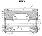
- the piston eye 16 has a bolt bore 5 which is opposite to the outer surface 17 of the Piston 1 is arranged set back. Between the outer surface 17 and the Bolt bore 5 is an annular recess 13 of larger diameter arranged so that the bolt 8 with its outer edge 11 in this by the Recess formed formed protrudes.
- the distance of the outer ends of the two pin bores 5 of the piston 1 is shorter than the length of the used bolt.
- the outer edge 11 of the bolt 8 is thus exposed and can not dig into the pin bore 5 under load, like this is the case with the prior art.
- the length L of the bolt hole becomes thereby be reduced and is smaller than in the illustration shown here the diameter D of the pin bore 5.
- the groove 6 for the locking ring 7 is in the annular recess 13, arranged so that between the locking ring 7 and the pin hole 5 an annular free space 20 is formed in which an oil reservoir for can form the lubrication of the pin bore 5.
- An oval snap ring can be provided as the bolt securing ring 7 due to the fact that it does not engage in the entire groove 6 (see FIG. 2), favors the oil flow from the outside in the direction of the pin bore 5.
- a vertical oil supply passage 14a is provided, which is vertical from above into the bolt hole 5 and a horizontal Connection channel 15 with the groove 4 for the oil control ring (not shown) in Connection is established.
- the oil conveyed into the groove 4 by the oil control ring becomes thus via the connection duct 15 and the vertical oil supply duct 14a directly fed to the bolt bore 5 or the bolt 8, whereby the Oil lubrication in this area is significantly improved.
- An oil drain channel 14b is arranged opposite in the piston eye 16, through the excess oil in the area of the pin bore 5 into the interior 19 of the piston 1 can flow off.
- the provision of an oil drain channel 14b provides also the advantage that the introduction of the oil supply channel 14a manufacturing technology is simplified.
- FIG. 2 is a side view of the piston 1 shown in FIG. 1 shown. It can clearly be seen that the pin retaining ring 7 is an oval Has shape and thus additional spaces 21 between the Bolt locking ring 7 and the annular recess 13 for the passage of Oil are present.
- the connecting channel 15 is arranged such that it with the lower groove surface 18 of the groove 4 is aligned, whereby the oil supply is improved.
Abstract
Description
Der Kolben 1' besitzt eine Brennraummulde 2, zwei Nuten 3a,b für die Kolbenringe und eine Nut 4 für den Ölabstreifring im Bereich der Kolbenringzone. Im Kolbenauge 16 ist eine Bolzenbohrung 5' angeordnet, in der der Kolbenbolzen 8 gelagert ist. Gegebenenfalls kann in der Bolzenbohrung 5' auch eine Lagerbuchse (nicht dargestellt) angeordnet sein.
- Fig. 1
- einen Vertikalschnitt durch einen erfindungsgemäßen Kolben,
- Fig. 2
- die Seitenansicht des in Fig. 1 gezeigten Kolbens,
- Fig. 3
- einen Vertikalschnitt durch einen Kolben gemäß des Standes der Technik.
- 1
- Kolben
- 1'
- Kolben
- 2
- Brennraummulde
- 3a,b
- Ringnut
- 4
- Ringnut für Ölabstreifring
- 5
- Bolzenbohrung
- 5'
- Bolzenbohrung
- 6
- Rille für Sicherungsring
- 7
- Bolzensicherungsring
- 7'
- Bolzensicherungsring
- 8
- Kolbenbolzen
- 9
- Augenachse
- 10
- Kolbenachse unter Belastung
- 11
- Bolzenkante
- 12
- Kolbenkante
- 13
- ringförmiger Einstich
- 14a
- vertikaler Zuführkanal
- 14b
- Ölablaßkanal
- 15
- horizontaler Verbindungskanal
- 16
- Kolbenauge
- 17
- Kolbenaußenfläche
- 18
- untere Nutfläche
- 19
- Innenraum
- 20
- ringförmiger Freiraum
- 21
- Freiraum
Claims (10)
- Kolben für Brennkraftmaschinen mit zwei Bolzenbohrungen für die Lagerung eines Kolbenbolzens, mit zwei Rillen für jeweils einen Bolzensicherungsring sowie mit Ringnuten in der Kolbenringzone für Kolbenringe und Ölabstreifring, dadurch gekennzeichnet,daß die Bolzenbohrung (5) beidseitig jeweils unter Ausbildung eines durchmessergrößeren Einstichs (13) gegenüber der Kolbenaußenfläche (17) zurückversetzt ist, unddaß die Rillen (6) für den Bolzensicherungsring (7) in den Einstichen (13) angeordnet sind.
- Kolbennach Anspruch 1, dadurch gekennzeichnet, daß der Einstich (13) ringförmig ist.
- Kolben nach Anspruch 1 oder 2, dadurch gekennzeichnet, daß die Rille (6) in Richtung der Augenachse (9) beabstandet zur Bolzenbohrung (5) angeordnet ist.
- Kolben nach einem der Ansprüche 1 bis 3, dadurch gekennzeichnet, daß die Länge L der Bolzenbohrung (5) kleiner gleich ihres Durchmessers D ist.
- Kolben nach einem der Ansprüche 1 bis 4, dadurch gekennzeichnet, daß jedes Kolbenauge (16) mindestens einen Ölzuführkanal (14a) aufweist, der einerseits in die Kolbenbohrung (5) mündet und andererseits mit der Nut (4) für den Ölabstreifring in Verbindung steht.
- Kolben nach einem der Ansprüche 1 bis 5, dadurch gekennzeichnet, daß der Ölzuführkanal (14a) über einen horizontalen Verbindungskanal (15) mit der Nut (4) in Verbindung steht.
- Kolben nach einem der Ansprüche 1 bis 6, dadurch gekennzeichnet, daß der Verbindungskanal (15) mit der unteren Nutfläche (18) der Nut (4) fluchtet.
- Kolben nach einem der Ansprüche 1 bis 6, dadurch gekennzeichnet, daß dem vertikalen Ölzuführungskanal (14a) ein vertikaler Ölauslaßkanal (14b) gegenüberliegt.
- Kolben nach einem der Ansprüche 1 bis 8 mit einem Kolbenbolzen, dadurch gekennzeichnet, daß der Kolbenbolzen (8) beidseitig gegenüber den Bolzenbohrungen (5) vorsteht.
- Kolben nach einem der Ansprüche 1 bis 9, dadurch gekennzeichnet, daß der Kolbenbolzen (8) mit ovalen Bolzensicherungsringen (7) gesichert ist.
Applications Claiming Priority (2)
| Application Number | Priority Date | Filing Date | Title |
|---|---|---|---|
| DE19955197 | 1999-11-16 | ||
| DE1999155197 DE19955197C2 (de) | 1999-11-16 | 1999-11-16 | Kolben für Brennkraftmaschinen |
Publications (3)
| Publication Number | Publication Date |
|---|---|
| EP1101923A2 true EP1101923A2 (de) | 2001-05-23 |
| EP1101923A3 EP1101923A3 (de) | 2002-02-06 |
| EP1101923B1 EP1101923B1 (de) | 2006-01-04 |
Family
ID=7929282
Family Applications (1)
| Application Number | Title | Priority Date | Filing Date |
|---|---|---|---|
| EP20000123900 Expired - Lifetime EP1101923B1 (de) | 1999-11-16 | 2000-11-03 | Kolben für Brennkraftmaschinen |
Country Status (2)
| Country | Link |
|---|---|
| EP (1) | EP1101923B1 (de) |
| DE (2) | DE19955197C2 (de) |
Cited By (2)
| Publication number | Priority date | Publication date | Assignee | Title |
|---|---|---|---|---|
| DE10255732A1 (de) * | 2002-11-29 | 2004-06-09 | Mahle Gmbh | Bolzennabe eines Kolbens für einen Verbrennungsmotor |
| FR2927666A3 (fr) * | 2008-02-15 | 2009-08-21 | Renault Sas | Piston pour moteur a combustion. |
Families Citing this family (1)
| Publication number | Priority date | Publication date | Assignee | Title |
|---|---|---|---|---|
| DE102019211336B4 (de) * | 2019-07-30 | 2023-02-02 | Federal-Mogul Nürnberg GmbH | Kolben mit Sicherungsringnut in der Bolzenbohrung für einen Verbrennungsmotor |
Citations (2)
| Publication number | Priority date | Publication date | Assignee | Title |
|---|---|---|---|---|
| DE4210056A1 (de) | 1992-03-27 | 1993-09-30 | Mahle Gmbh | Hubkolben eines Verbrennungsmotors |
| DE4438703A1 (de) | 1994-10-29 | 1996-05-02 | Mahle Gmbh | Leichtmetallkolben mit Kühlkanal für Verbrennungsmotoren |
Family Cites Families (9)
| Publication number | Priority date | Publication date | Assignee | Title |
|---|---|---|---|---|
| GB356612A (en) * | 1930-12-31 | 1931-09-10 | Thomas Craig English | Improvements in trunk pistons |
| GB757226A (en) * | 1953-11-17 | 1956-09-19 | Bristol Pneumatic Tools Ltd | Improved means for mounting a gudgeon pin in a piston |
| FR1300937A (fr) * | 1961-06-30 | 1962-08-10 | Axe élastique pour piston | |
| US3494262A (en) * | 1967-08-09 | 1970-02-10 | Trw Inc | Piston |
| US3515035A (en) * | 1968-07-05 | 1970-06-02 | Brunswick Corp | Piston pin lubrication |
| JPH063263B2 (ja) * | 1986-07-07 | 1994-01-12 | 日本特殊陶業株式会社 | ピストンピンとスナツプリングとの潤滑機構 |
| US4796517A (en) * | 1986-07-08 | 1989-01-10 | Ngk Spark Plug Co., Ltd. | Metal piston and ceramic piston pin assembly |
| DE8815283U1 (de) * | 1988-12-08 | 1989-02-16 | Scheufler, Roland, 7107 Neckarsulm, De | |
| US5694829A (en) * | 1995-04-25 | 1997-12-09 | Yamaha Hatsudoki Kabushiki Kaisha | Piston and piston pin arrangement for reciprocating machine |
-
1999
- 1999-11-16 DE DE1999155197 patent/DE19955197C2/de not_active Expired - Lifetime
-
2000
- 2000-11-03 DE DE50012012T patent/DE50012012D1/de not_active Expired - Fee Related
- 2000-11-03 EP EP20000123900 patent/EP1101923B1/de not_active Expired - Lifetime
Patent Citations (2)
| Publication number | Priority date | Publication date | Assignee | Title |
|---|---|---|---|---|
| DE4210056A1 (de) | 1992-03-27 | 1993-09-30 | Mahle Gmbh | Hubkolben eines Verbrennungsmotors |
| DE4438703A1 (de) | 1994-10-29 | 1996-05-02 | Mahle Gmbh | Leichtmetallkolben mit Kühlkanal für Verbrennungsmotoren |
Cited By (3)
| Publication number | Priority date | Publication date | Assignee | Title |
|---|---|---|---|---|
| DE10255732A1 (de) * | 2002-11-29 | 2004-06-09 | Mahle Gmbh | Bolzennabe eines Kolbens für einen Verbrennungsmotor |
| US7278390B2 (en) | 2002-11-29 | 2007-10-09 | Mahle Gmbh | Piston-pin boss of a piston for an internal combustion engine |
| FR2927666A3 (fr) * | 2008-02-15 | 2009-08-21 | Renault Sas | Piston pour moteur a combustion. |
Also Published As
| Publication number | Publication date |
|---|---|
| DE19955197A1 (de) | 2001-05-23 |
| EP1101923A3 (de) | 2002-02-06 |
| EP1101923B1 (de) | 2006-01-04 |
| DE19955197C2 (de) | 2003-09-18 |
| DE50012012D1 (de) | 2006-03-30 |
Similar Documents
| Publication | Publication Date | Title |
|---|---|---|
| DE102004048939B4 (de) | Pleuelstange mit Schmiermittelrohr | |
| DE60220925T2 (de) | Einstückiger kolben für dieselmotoren | |
| DE19828847B4 (de) | Kolbenbolzenbuchse | |
| DE4133033A1 (de) | Kipphebel | |
| DE102005030307B4 (de) | Kurbelwellenhauptlager und Massenausgleichsgetriebelager | |
| DE19942105B4 (de) | Schmiervorrichtung für Verbrennungskraftmaschine | |
| DE3534536A1 (de) | Kolben fuer eine brennkraftmaschine | |
| EP2236800B1 (de) | Zylinder mit Mitteln zur Verteilung von Schmiermittel | |
| EP1278951B1 (de) | Verbrennungsmotor mit einem gebauten kolben | |
| DE3722435A1 (de) | Schmiereinrichtung fuer eine brennkraftmaschine | |
| DE102006013905A1 (de) | Kolben für einen Verbrennungsmotor | |
| DE10130253B4 (de) | Gleitlager, insbesondere einer Pleuelstange für Hubkolbenbrennkraftmaschinen | |
| CH615253A5 (en) | Crosshead journal bearing for piston machines, in particular for diesel internal combustion engines | |
| EP1101923B1 (de) | Kolben für Brennkraftmaschinen | |
| DE19641811A1 (de) | Ventilanordnung für Verbrennungsmotoren | |
| EP2758678B1 (de) | Pleuel | |
| EP1101904B1 (de) | Kolbenmaschine und Verteilelement | |
| DE3707462C2 (de) | ||
| DE102009018981A1 (de) | Kolben für eine Hubkolbenmaschine | |
| DE4325903C1 (de) | Kolbenbolzenlagerung | |
| DE60007503T2 (de) | Ventilsteuerungseinrichtung für eine Brennkraftmaschine | |
| EP2094997B1 (de) | Kolben für einen verbrennungsmotor | |
| EP1034390B1 (de) | Kolbeneinheit | |
| DE19544418C1 (de) | Kolben-Pleuelverbindung | |
| DE2604038A1 (de) | Kolben fuer verbrennungskraftmaschinen |
Legal Events
| Date | Code | Title | Description |
|---|---|---|---|
| PUAI | Public reference made under article 153(3) epc to a published international application that has entered the european phase |
Free format text: ORIGINAL CODE: 0009012 |
|
| AK | Designated contracting states |
Kind code of ref document: A2 Designated state(s): DE FR GB IT SE Kind code of ref document: A2 Designated state(s): AT BE CH CY DE DK ES FI FR GB GR IE IT LI LU MC NL PT SE TR |
|
| AX | Request for extension of the european patent |
Free format text: AL;LT;LV;MK;RO;SI |
|
| PUAL | Search report despatched |
Free format text: ORIGINAL CODE: 0009013 |
|
| AK | Designated contracting states |
Kind code of ref document: A3 Designated state(s): AT BE CH CY DE DK ES FI FR GB GR IE IT LI LU MC NL PT SE TR |
|
| AX | Request for extension of the european patent |
Free format text: AL;LT;LV;MK;RO;SI |
|
| RIC1 | Information provided on ipc code assigned before grant |
Free format text: 7F 02F 3/00 A, 7F 16J 1/18 B, 7F 16J 1/08 B |
|
| 17P | Request for examination filed |
Effective date: 20020130 |
|
| AKX | Designation fees paid |
Free format text: DE FR GB IT SE |
|
| 17Q | First examination report despatched |
Effective date: 20041125 |
|
| GRAP | Despatch of communication of intention to grant a patent |
Free format text: ORIGINAL CODE: EPIDOSNIGR1 |
|
| RIN1 | Information on inventor provided before grant (corrected) |
Inventor name: HOPPE-BOEKEN, PETER-CLEMENS |
|
| GRAS | Grant fee paid |
Free format text: ORIGINAL CODE: EPIDOSNIGR3 |
|
| GRAA | (expected) grant |
Free format text: ORIGINAL CODE: 0009210 |
|
| AK | Designated contracting states |
Kind code of ref document: B1 Designated state(s): DE FR GB IT SE |
|
| PG25 | Lapsed in a contracting state [announced via postgrant information from national office to epo] |
Ref country code: IT Free format text: LAPSE BECAUSE OF FAILURE TO SUBMIT A TRANSLATION OF THE DESCRIPTION OR TO PAY THE FEE WITHIN THE PRESCRIBED TIME-LIMIT;WARNING: LAPSES OF ITALIAN PATENTS WITH EFFECTIVE DATE BEFORE 2007 MAY HAVE OCCURRED AT ANY TIME BEFORE 2007. THE CORRECT EFFECTIVE DATE MAY BE DIFFERENT FROM THE ONE RECORDED. Effective date: 20060104 |
|
| REG | Reference to a national code |
Ref country code: GB Ref legal event code: FG4D Free format text: NOT ENGLISH |
|
| REG | Reference to a national code |
Ref country code: SE Ref legal event code: TRGR |
|
| REF | Corresponds to: |
Ref document number: 50012012 Country of ref document: DE Date of ref document: 20060330 Kind code of ref document: P |
|
| GBT | Gb: translation of ep patent filed (gb section 77(6)(a)/1977) |
Effective date: 20060309 |
|
| ET | Fr: translation filed | ||
| RAP2 | Party data changed (patent owner data changed or rights of a patent transferred) |
Owner name: FEDERAL-MOGUL WIESBADEN GMBH |
|
| PLBE | No opposition filed within time limit |
Free format text: ORIGINAL CODE: 0009261 |
|
| STAA | Information on the status of an ep patent application or granted ep patent |
Free format text: STATUS: NO OPPOSITION FILED WITHIN TIME LIMIT |
|
| 26N | No opposition filed |
Effective date: 20061005 |
|
| PGFP | Annual fee paid to national office [announced via postgrant information from national office to epo] |
Ref country code: IT Payment date: 20081124 Year of fee payment: 9 Ref country code: SE Payment date: 20081107 Year of fee payment: 9 |
|
| PGFP | Annual fee paid to national office [announced via postgrant information from national office to epo] |
Ref country code: FR Payment date: 20081106 Year of fee payment: 9 |
|
| PGFP | Annual fee paid to national office [announced via postgrant information from national office to epo] |
Ref country code: DE Payment date: 20081128 Year of fee payment: 9 |
|
| PGFP | Annual fee paid to national office [announced via postgrant information from national office to epo] |
Ref country code: GB Payment date: 20081008 Year of fee payment: 9 |
|
| EUG | Se: european patent has lapsed | ||
| GBPC | Gb: european patent ceased through non-payment of renewal fee |
Effective date: 20091103 |
|
| REG | Reference to a national code |
Ref country code: FR Ref legal event code: ST Effective date: 20100730 |
|
| PG25 | Lapsed in a contracting state [announced via postgrant information from national office to epo] |
Ref country code: FR Free format text: LAPSE BECAUSE OF NON-PAYMENT OF DUE FEES Effective date: 20091130 |
|
| PG25 | Lapsed in a contracting state [announced via postgrant information from national office to epo] |
Ref country code: DE Free format text: LAPSE BECAUSE OF NON-PAYMENT OF DUE FEES Effective date: 20100601 |
|
| PG25 | Lapsed in a contracting state [announced via postgrant information from national office to epo] |
Ref country code: GB Free format text: LAPSE BECAUSE OF NON-PAYMENT OF DUE FEES Effective date: 20091103 |
|
| PG25 | Lapsed in a contracting state [announced via postgrant information from national office to epo] |
Ref country code: IT Free format text: LAPSE BECAUSE OF NON-PAYMENT OF DUE FEES Effective date: 20091103 |
|
| PG25 | Lapsed in a contracting state [announced via postgrant information from national office to epo] |
Ref country code: SE Free format text: LAPSE BECAUSE OF NON-PAYMENT OF DUE FEES Effective date: 20091104 |