EP1101622A1 - Dispositif d'impression et procédé pour diminuer la charge de l'alimentation de puissance pour le dispositif d'impression - Google Patents
Dispositif d'impression et procédé pour diminuer la charge de l'alimentation de puissance pour le dispositif d'impression Download PDFInfo
- Publication number
- EP1101622A1 EP1101622A1 EP00310194A EP00310194A EP1101622A1 EP 1101622 A1 EP1101622 A1 EP 1101622A1 EP 00310194 A EP00310194 A EP 00310194A EP 00310194 A EP00310194 A EP 00310194A EP 1101622 A1 EP1101622 A1 EP 1101622A1
- Authority
- EP
- European Patent Office
- Prior art keywords
- electric power
- distance
- pertains
- printing
- Prior art date
- Legal status (The legal status is an assumption and is not a legal conclusion. Google has not performed a legal analysis and makes no representation as to the accuracy of the status listed.)
- Granted
Links
Images


Classifications
-
- B—PERFORMING OPERATIONS; TRANSPORTING
- B41—PRINTING; LINING MACHINES; TYPEWRITERS; STAMPS
- B41J—TYPEWRITERS; SELECTIVE PRINTING MECHANISMS, i.e. MECHANISMS PRINTING OTHERWISE THAN FROM A FORME; CORRECTION OF TYPOGRAPHICAL ERRORS
- B41J13/00—Devices or arrangements of selective printing mechanisms, e.g. ink-jet printers or thermal printers, specially adapted for supporting or handling copy material in short lengths, e.g. sheets
- B41J13/0009—Devices or arrangements of selective printing mechanisms, e.g. ink-jet printers or thermal printers, specially adapted for supporting or handling copy material in short lengths, e.g. sheets control of the transport of the copy material
- B41J13/0027—Devices or arrangements of selective printing mechanisms, e.g. ink-jet printers or thermal printers, specially adapted for supporting or handling copy material in short lengths, e.g. sheets control of the transport of the copy material in the printing section of automatic paper handling systems
-
- B—PERFORMING OPERATIONS; TRANSPORTING
- B41—PRINTING; LINING MACHINES; TYPEWRITERS; STAMPS
- B41J—TYPEWRITERS; SELECTIVE PRINTING MECHANISMS, i.e. MECHANISMS PRINTING OTHERWISE THAN FROM A FORME; CORRECTION OF TYPOGRAPHICAL ERRORS
- B41J11/00—Devices or arrangements of selective printing mechanisms, e.g. ink-jet printers or thermal printers, for supporting or handling copy material in sheet or web form
- B41J11/0005—Curl smoothing, i.e. smoothing down corrugated printing material, e.g. by pressing means acting on wrinkled printing material
-
- B—PERFORMING OPERATIONS; TRANSPORTING
- B41—PRINTING; LINING MACHINES; TYPEWRITERS; STAMPS
- B41J—TYPEWRITERS; SELECTIVE PRINTING MECHANISMS, i.e. MECHANISMS PRINTING OTHERWISE THAN FROM A FORME; CORRECTION OF TYPOGRAPHICAL ERRORS
- B41J11/00—Devices or arrangements of selective printing mechanisms, e.g. ink-jet printers or thermal printers, for supporting or handling copy material in sheet or web form
- B41J11/007—Conveyor belts or like feeding devices
-
- B—PERFORMING OPERATIONS; TRANSPORTING
- B41—PRINTING; LINING MACHINES; TYPEWRITERS; STAMPS
- B41J—TYPEWRITERS; SELECTIVE PRINTING MECHANISMS, i.e. MECHANISMS PRINTING OTHERWISE THAN FROM A FORME; CORRECTION OF TYPOGRAPHICAL ERRORS
- B41J11/00—Devices or arrangements of selective printing mechanisms, e.g. ink-jet printers or thermal printers, for supporting or handling copy material in sheet or web form
- B41J11/36—Blanking or long feeds; Feeding to a particular line, e.g. by rotation of platen or feed roller
- B41J11/42—Controlling printing material conveyance for accurate alignment of the printing material with the printhead; Print registering
Definitions
- the present invention relates to a printing apparatus and power supply load reduction method for a printing apparatus and, more particularly, to a printing apparatus having a plurality of full-line print heads each having a print element array corresponding to the width of a recording medium, and a power supply load reduction method for that printing apparatus.
- an information output device for, e.g., a wordprocessor, personal computer, facsimile apparatus, and the like, a printer that prints information such as desired characters, images, and the like on a sheet-like print medium such as a paper sheet, film, or the like is known.
- a full-line printing apparatus which has a print head comprising a print element (nozzle) array corresponding to a printing region, and prints while conveying a print medium, is prevalently used since it can achieve a higher-speed print process.
- a plurality of print heads that eject different color inks line up in the convey direction of the print medium and are controlled to simultaneously eject inks, thus preventing any printing speed drop even in a color print process.
- a printing apparatus having a full-line print head requires a power supply capacity that can simultaneously drive all nozzles of the print head since data corresponding to one raster are to be printed simultaneously.
- a printing apparatus that achieves a color print process using a plurality of full-line print heads requires a still larger power supply capacity, i.e., a power supply capacity that can drive all nozzles of a plurality of print heads so as to prevent any printing speed drop.
- the present invention has been made in consideration of the above situation, and has as a concern to provide a printing apparatus which can prevent deterioration of image quality and extreme drop of the printing speed without unwantedly increasing the power supply capacity, and a power supply load reduction method for the printing apparatus.
- a printing apparatus having a plurality of full-line print heads each having a print element array corresponding to a width of a print medium, convey means for conveying the print medium to a position where the print heads can print, print electric power computation means for computing a numerical value that pertains to electric power to be supplied to the print heads upon printing print data when print data that uses a plurality of print media is received, determination means for determining if the numerical value that pertains to the electric power is larger than a predetermined value, distance setting means for setting a distance between the plurality of print media in accordance with the determination by the determination means, and convey control means for controlling the convey means to make the distance between the print media be the distance set by the distance setting means upon conveying the plurality of print media.
- the invention provides, a power supply load reduction method for a printing apparatus having a plurality of full-line print heads each having a print element array corresponding to a width of a print medium, the method comprising the convey step of conveying the print medium to a position where the print heads can print, the print electric power computation step of computing a numerical value that pertains to electric power to be supplied to the print heads upon printing print data when print data that uses a plurality of print media is received, the determination step of determining if the numerical value that pertains to the electric power is larger than a predetermined value, the distance setting step of setting a distance between the plurality of print media in accordance with the determination in the determination step, and the convey control step of controlling the convey step to make the distance between the print media be the distance set in the distance setting step upon conveying the plurality of print media.
- a print duty or the like as the number of print elements used in a print process with respect to the total number of print elements is computed as a numerical value that pertains to electric power to be supplied to the print heads upon recording the received print data, and the computed value is compared with a predetermined value to determine a distance between neighboring print media, and the print media are controlled to be conveyed at the set print medium distance.
- the distance between the neighboring print media is increased so that the numerical value that pertains to electric power becomes equal to or smaller than the predetermined value.
- a ratio of the number of print elements to be driven upon printing the print data to the number of all the print elements of the print heads is preferably used.
- the distance setting means selects and sets the distance between the print media from a plurality of pre-set values, thus simplifying processes.
- the apparatus preferably further comprises means for changing the predetermined value in correspondence with a size of the print medium and a print region of the print data.
- the apparatus preferably further comprises table creation means for storing the predetermined value corresponding to the size of the print medium and the print region of the print data.
- the printing apparatus preferably further comprises memory means for storing the print data in units of pages, and the print electric power computation means computes the numerical value that pertains to the electric power when print data of the next page to be printed is stored in the memory means.
- Figs. 1 and 2 are sectional views showing the internal structure of an ink-jet printing apparatus according to a preferred embodiment of the present invention, in which Fig. 1 is a sectional view showing the overall arrangement of the printing apparatus, and Fig. 2 is a sectional view showing the structure of a sheet convey section 3 of the printing apparatus.
- the printing apparatus of this embodiment has an automatic sheet feeder, and comprises a sheet feed section 2, sheet convey section 3, exhaust section 4, and print head section 7. An outline of the printing apparatus will be explained in turn below in units of these sections.
- (I) Sheet Feed Section, (II) Sheet Convey Section, (III) Print Head Section, and (IV) Exhaust Section will be described in turn using Figs. 1 and 2.
- the sheet feed section 2 is constructed by attaching a pressing plate 21 on which print paper sheets P as print medium are stacked, and a rotary sheet feed member 22 for feeding a print paper sheet P to a base 20.
- the pressing plate 21 is rotatable about a rotation shaft a which is coupled to the base 20, and is biased against the rotary sheet feed member 22 by a pressing plate spring 24.
- a separation pad 25 which is formed of a material having a large coefficient of friction such as synthetic leather or the like is provided on the pressing plate 21 at a position opposing the rotary sheet feed member 22 so as to prevent multiple feed of print paper sheets P.
- the base 20 has a separation pawl 26 which covers a corner of print paper sheets P in one direction, and separates print paper sheets one by one, and a release cam (not shown) for releasing a contact between the pressing plate 21 and rotary sheet feed member 22.
- the release cam presses the pressing plate 21 down to a predetermined position in a standby state. As a result, the contact between the pressing plate 21 and rotary sheet feed member 22 is released.
- the release cam separates from the pressing plate 21, which moves upward, and the rotary sheet feed member 22 is brought into contact with a print paper sheet P.
- the print paper sheet P is picked up and begins to be fed.
- the print paper sheet P is separated by the separation pawl 26 one by one, and is fed to the sheet convey section 3.
- the rotary sheet feed member 22 rotates until it feeds the print paper sheet P into the sheet convey section 3, and the standby state in which the contact between the print paper sheet P and rotary sheet feed member 22 is released is set again, thus turning off the driving force from the convey roller 32.
- Reference numeral 90 denotes a rotary sheet feed member used when a sheet is manually inserted.
- a print paper sheet P set on a manual insert tray 91 is picked up by the rotary sheet feed member 90 in accordance with a print command signal from a computer, and is conveyed to the convey roller 32.
- the sheet convey section 3 has a conveyor belt 31 which attracts and conveys a print paper sheet P, and a PE sensor (not shown).
- the conveyor belt 31 is driven by a driving roller 34, and is supported by the convey roller 32 and a pressure roller 35 as driven rollers so as to form a loop.
- a pinch roller 33 which is driven by the conveyor belt 31 is provided at a position opposing the convey roller 32 to be in contact with the conveyor belt 31.
- the pinch roller 33 is pressed against the conveyor belt 31 by a spring (not shown) to guide a print paper sheet P to a print section.
- upper and lower guides 27 and 28 which guide a print paper sheet P are provided at an entrance of the sheet convey section 3 that receives the print paper sheet P.
- the upper guide 27 has a PE sensor lever 29 which informs the PE sensor (not shown) of detection of the leading and trailing ends of a print paper sheet P.
- the print head section 7 for forming an image on the basis of image information is provided downstream the convey roller 32 in the convey direction of a print paper sheet.
- a print paper sheet P fed to the sheet convey section 3 is fed to a roller pair, i.e., the convey roller 32 and pinch roller 33 while being guided by the upper and lower guides 27 and 28.
- the PE sensor lever 29 detects the leading end of the incoming print paper sheet P, thus obtaining the print position of the print paper sheet P.
- the print paper sheet P is conveyed by rotating the conveyor belt 31 via the convey roller 32 by an ultrasonic motor to be described later.
- the print head section 7 of this embodiment uses full-line ink-jet print heads each having an array of a plurality of nozzles each of which constitutes a print element extending in a direction perpendicular to the convey direction of a print paper sheet P. These heads are arranged at a given spacing in the order of 7K (black), 7C (cyan), 7M (magenta), and 7Y (yellow) from the upstream side of the convey direction of the print paper sheet P, and the print head section 7 is attached to a head holder 7A.
- Each print head 7 can apply heat to ink within each nozzles using heaters or the like.
- the ink causes film boiling due to this heat, and is ejected from each nozzle 70 of the print head 7 by a change in pressure caused by growth or shrinkage of bubbles resulting from the film boiling, thus forming an image on the print paper sheet P.
- the electrothermal transducer such as the heater is employed as an ink ejecting element which constitutes the print element with the nozzle.
- the ink ejecting element is not limited to this construction.
- a piezoelectric element can also be employed as the ink ejecting element.
- One end of the print head section 7 is pivotally supported by a shaft 71, and a projection 7A formed on the other end of the print head section 7 engages with a rail 72, thus defining a spacing (sheet spacing) between the nozzle surface and print paper sheet P.
- an ink tank that stores ink and each print head may be integrally formed to constitute an exchangeable ink cartridge.
- these ink tank and print head may be independently arranged, and the ink tank alone may be exchanged when ink is used up.
- the exhaust section 4 is comprised of an exhaust roller 41 and spur 42.
- a print paper sheet P that has undergone image formation in the print section is conveyed while being clamped between the exhaust roller 41 and spur 42, and is exhausted onto an exhaust tray 43.
- Reference numeral 31 denotes a conveyor belt which moves while attracting and holding a print paper sheet P, is made up of a synthetic resin such as polyethylene, polycarbonate, or the like having a thickness of about 0.1 to 0.2 mm, and has an endless belt shape.
- Reference numeral 36 denotes an attractive force generation means, which is fixed at a position opposing the print head section 7, and applies a voltage of around 0.5 kV to 10 kV to generate an attractive force on the conveyor belt 31 corresponding to the print region of the print head section 7.
- the means 36 is connected to a high-voltage power supply (not shown) that generates a predetermined high voltage.
- reference numerals 32, 34, and 35 denote rollers which support the conveyor belt 31 and give an appropriate tension to that belt.
- the roller 34 is coupled to a sheet feed motor 50.
- a sheet pressing member 39 as pressing means for pressing the print paper sheet P against the conveyor belt side is attached to have a rotation shaft of the pinch roller 33 as the center of rotation, and is biased toward the conveyor belt 31 by a biasing means (not shown).
- the sheet pressing member 39 is formed of a conductive metal plate.
- Reference numeral 38 denotes a pair of cleaning rollers which pinch the belt 31, and can absorb ink to remove soil such as ink attached to the belt 31. Also, these rollers 38 are formed of open cell sponge having a small cell diameter (preferably 10 ⁇ m to 30 ⁇ m) to prevent poor durability.
- a print paper sheet P is guided to the print section while being clamped between the pinch roller 33 and conveyor belt 31, and enters an attractive force generation portion while being pressed against the conveyor roller 31 by the sheet pressing member 39.
- the print paper sheet P is attracted by a flat portion of the conveyor belt 31 by an attractive force supplied from the attractive force generation means 36, and is conveyed in the direction of an arrow a by the sheet feed motor 50 and roller 34 while undergoing the print process by the print head section.
- the print process can be done while the ejection nozzles at the end portion of the print head section and the end portion of the print paper sheet P are close to each other, thus obtaining a high-precision print image.
- the print paper sheet P When ink is ejected in large quantity on the print paper sheet P, the print paper sheet P swells and crinkles. In this case, since the print paper sheet P is attracted on the conveyor belt 31 by the attractive force of the attractive force generation means 36 and the pressing force of the sheet pressing member 39, the print paper sheet P can be prevented from floating toward the head section 7. Therefore, the head section 7 does not contact the print paper sheet P, thus allowing a stable print process. Even when the end portion of the print paper sheet P crinkles or curls due to changes in environment including temperature, humidity, or the like, the sheet pressing member 39 can press the print paper sheet P against the conveyor belt 31, and can convey it to the attractive force generation portion while removing crinkling and curl, thus allowing stable attraction in the print section.
- Fig. 3 is a block diagram showing the arrangement of a controller of the ink-jet printing apparatus according to the present invention, and devices controlled by the controller.
- the conveyor belt position sensor 102 is provided on the back surface side of the conveyor belt at a position between the convey roller 32 and pressure roller 35 although it is not shown in Figs. 1 and 2.
- Reference numeral 80 denotes a controller.
- Reference numeral 80a denotes a CPU; 80b, a ROM for storing a program; 80c, a work memory required for control; and 80d, a gate array. These components 80a to 80d are connected to each other via a system bus.
- the gate array 80d outputs control signals for the driving roller motor and rotary sheet feed member motor, a control signal for the cleaning roller solenoid, an image signal to the print heads, and a control signal for the print heads, and reads information from a sensor for detecting soil on the conveyor belt and the PE sensor.
- Figs. 4A to 4C show the print processes on a print paper sheet conveyed by the conveyor belt 31 in the ink-jet printing apparatus of this embodiment. As shown in Figs. 4A to 4C, the number of print heads to be driven simultaneously changes depending on the positional relationship between print paper sheets P1 and P2, and the print heads.
- the number of print heads to be driven simultaneously is 3.
- the print heads 7K and 7Y are respectively located above the print paper sheets P1 and P2, and other print heads fall outside these print paper sheets. Therefore, the number of print heads to be driven simultaneously is 2. In this manner, the number of print heads to be simultaneously driven changes along with an elapse of time depending on the position of the print paper sheet relative to the print heads.
- a print sheet distance d2 as the distance between two print paper sheets P1 and P2 to be conveyed successively is larger than a print sheet distance d1 shown in Figs. 4A and 4B.
- the positional relationship between the print head 7K and print paper sheet P2 is the same as that in Fig. 4B, but the positional relationship between the print head 7Y and print paper sheet P1 is different from Fig. 4B, i.e., the print head 7Y falls outside the print paper sheet P1 like the print heads 7C and 7M.
- the number of print heads to be driven simultaneously is only one. In this manner, the number of print heads to be driven simultaneously also changes depending on the print sheet distance.
- Figs. 5A to 5C are graphs showing a change in print duty when a predetermined print image is successively printed on two pages in the ink-jet printing apparatus of this embodiment.
- the ordinate plots the print duty (%)
- the abscissa plots the relative position (raster) from the leading end of the print paper sheet with reference to the print head 7K.
- the print duty is the ratio of the number of nozzles to be actually driven to the total number of nozzles of all the print heads of the ink-jet printing apparatus.
- Figs. 5A, 5B, and 5C respectively show the print duties when the print sheet distances of 60 mm, 80 mm, and 100 mm are set.
- the maximum values of the print duties are respectively 9.6%, 7.6%, and 6.8%. That is, even when the print image to be printed remains the same, the maximum value of the print duty changes largely if the print sheet distance changes.
- the power supply load of the printing apparatus is controlled to become equal to or smaller than a predetermined value by exploiting the relationship between the print sheet distance and print duty.
- an allowable print duty acquisition process shown in Fig. 6 is launched to acquire an allowable print duty, which represents the print duty that allows the print process using the built-in power supply of the ink-jet printing apparatus.
- an allowable electric power capacity that the built-in power supply of the ink-jet printing apparatus can supply to drive the print heads is read out from the ROM 80B (step S101). Then, the allowable print duty is computed based on consumption power per ejection nozzle of the print head, and the total number of nozzles of all the print heads and is saved in the memory 80c (step S102).
- the print sheet distance control process shown in Fig. 7 is launched during the print process of an image, which starts in response to a print request from the host. As for the timing, this process is launched when all next print images to be printed are stored in the memory 80c of the ink-jet printing apparatus in a printable data format, and a print paper sheet on which the print images are printed has reached the position of a registration roller immediately before it is supplied to the conveyor belt 31.
- the registration roller (not shown) is disposed upstream the pinch roller 33, and is used to adjust the supply timing of a print paper sheet to the conveyor belt 31.
- step S201 the allowable print duty saved by the allowable print duty acquisition process is read out from the memory 80c (step S201). Subsequently, an allowable print sheet distance as a maximum value of the print sheet distance is acquired from the ROM 80b (step S202), and a normal print sheet distance is acquired from the ROM 80b (step S203).
- Transition data of the print duty shown in Figs. 5A to 5C is analyzed on the basis of the current print image, the next print image, and the acquired print sheet distance (step S204), and the maximum value of the print duty is extracted from this transition data and is set as a maximum print duty (step S205).
- step S206 It is then checked if the acquired maximum print duty is equal to or smaller than the allowable print duty.
- the current print sheet distance is saved in the memory 80c as information for the print sheet supply timing of the registration roller (step S210), thus ending the process.
- the process for driving the registration roller and supplying a print paper sheet to the conveyor belt 31 is done by a sheet feed control process as another control program executed by the CPU 80a.
- step S206 If it is determined in step S206 that the maximum print duty has exceeded the allowable print duty, the print sheet distance is increased by a predetermined length (step S207), and after it is confirmed that the new print sheet distance does not exceed the allowable print sheet distance acquired in step S202 (step S208), the flow returns to step S204. Then, the print sheet distance is increased by a predetermined length until the maximum print duty becomes equal to or smaller than the allowable print duty.
- step S208 If the condition that the print duty becomes equal to or smaller than the allowable print duty cannot be found even after the processes in steps S204 to S208 are repeated, the print sheet distance eventually becomes larger than the allowable print sheet distance in step S208. In this case, a normal print sheet distance is read out from the ROM 80b (step S209), and is saved in the memory 80c so that it can be used in determination of the print paper sheet supply timing in the sheet feed control process (step S210), thus ending the process.
- control programs and data stored in the ROM 80b are loaded onto the memory 80c upon execution.
- control programs and data recorded on a storage medium such as a flexible disk or the like may be recorded from a host computer 112a to which an external storage device 112b is connected to a flash ROM 80b provided to an ink-jet printing apparatus 112c, and may then be loaded from the flash ROM 80b onto the memory 80c.
- Fig. 8 shows a case wherein a flexible disk drive is used as the external storage device 112b connected to the host computer 112a, and control programs and data are stored in a flexible disk 113.
- a storage medium that stores the control programs and data is not limited to the flexible disk, but may be a CD-ROM, IC memory card, and the like.
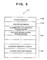
- Fig. 9- shows a memory map when the flexible disk 113 is used as the storage medium for storing the control programs and data.
- the memory map has a volume information storage area 113a, a directory information storage area 113b, a control program storage area 113c for storing predetermined control programs (the allowable duty acquisition process program, print sheet distance control program, and the like), and a data storage area 113d for storing data (the allowable power supply capacity, allowable print sheet distance, the number of nozzles of the print heads, and the like) used in these control programs.
- predetermined control programs the allowable duty acquisition process program, print sheet distance control program, and the like
- data storage area 113d for storing data (the allowable power supply capacity, allowable print sheet distance, the number of nozzles of the print heads, and the like) used in these control programs.
- the flexible disk 113 with such memory map is read by the flexible disk drive 112b connected to the host computer 112a to download the control programs and data to the ink-jet printing apparatus.
- a stable print process can be done even using a low-cost power supply without any deterioration of print quality and extreme drop of the print speed.
- a computation is made with reference to the total number of nozzles of the print heads upon acquiring the allowable print duty.
- the ink-jet printing apparatus does not print on the entire surface of a print sheet having a maximum size, and the region to be printed is normally smaller than the print sheet size or a print sheet size is smaller than the maximum sheet. For this reason, in case of the full-line print head, the number of nozzles normally used in a print process is smaller than the total number of nozzles of the print heads.
- the step of computing the number of nozzles used as a reference upon computing the allowable print duty (to be referred to as the reference number of nozzles) on the basis of the print size and effective print region, and setting the reference number of nozzles to be a value that matches an actual print process is added immediately before step S102 in Fig. 6.
- the reference number of nozzles can be set to be a value that matches an actual print request every time the print request is sent.
- a plurality of allowable print duties computed in advance are stored so as to shorten the computation time of the allowable print duty.
- the allowable print duty is computed before the print process starts.
- values computed in advance may be stored in the ROM 80b.
- a table that stores some print region widths and a plurality of allowable print duties computed in advance in correspondence with each other may be recorded in the ROM 80b.
- the print sheet distance is controlled in correspondence with the number of print heads used in a print process.
- the print sheet distance that sets the number of print heads to be driven simultaneously to be 1 changes at the timing across two print paper sheets, as shown in Fig. 4C.
- the print sheet is employed as a print medium.
- the print medium for the present invention is not limited to the print sheet.
- an OHP sheet or a woven fabric can be employed as a print medium.
- droplets discharged from the printing head are ink droplets, and a liquid stored in the ink tank is ink.
- the liquid to be stored in the ink tank is not limited to ink.
- a treatment solution to be discharged onto a printing medium so as to improve the fixing property or water resistance of a printed image or its image quality may be stored in the ink tank.
- the embodiment described above has exemplified a printer, which comprises means (e.g., an electrothermal transducer, laser beam generator, and the like) for generating heat energy as energy utilized upon execution of ink discharge, and causes a change in state of an ink by the heat energy, among the ink-jet printers.
- means e.g., an electrothermal transducer, laser beam generator, and the like
- heat energy as energy utilized upon execution of ink discharge
- causes a change in state of an ink by the heat energy among the ink-jet printers.
- signals disclosed in U.S. Patent Nos. 4,463,359 and 4,345,262 are suitable. Note that further excellent printing can be performed by using the conditions described in U.S. Patent No. 4,313,124 of the invention which relates to the temperature rise rate of the heat acting surface.
- the arrangement using U.S. Patent Nos. 4,558,333 and 4,459,600 which disclose the arrangement having a heat acting portion arranged in a flexed region is also included in the present invention.
- the present invention can be effectively applied to an arrangement based on Japanese Patent Laid-Open No. 59-123670 which discloses the arrangement using a slot common to a plurality of electrothermal transducers as a discharge portion of the electrothermal transducers, or Japanese Patent Laid-Open No. 59-138461 which discloses the arrangement having an opening for absorbing a pressure wave of heat energy in correspondence with a discharge portion.
- a full line type printing head having a length corresponding to the width of a maximum printing medium which can be printed by the printer, either the arrangement which satisfies the full-line length by combining a plurality of printing heads as disclosed in the above specification or the arrangement as a single printing head obtained by forming printing heads integrally can be used.
- an exchangeable chip type printing head as described in the above embodiment, which can be electrically connected to the apparatus main unit and can receive an ink from the apparatus main unit upon being mounted on the apparatus main unit but also a cartridge type printing head in which an ink tank is integrally arranged on the printing head itself can be applicable to the present invention.
- recovery means for the printing head, preliminary auxiliary means, and the like provided as an arrangement of the printer of the present invention since the printing operation can be further stabilized.
- examples of such means include, for the printing head, capping means, cleaning means, pressurization or suction means, and preliminary heating means using electrothermal transducers, another heating element, or a combination thereof. It is also effective for stable printing to provide a preliminary discharge mode which performs discharge independently of printing.
- a printing mode of the printer not only a printing mode using only a primary color such as black or the like, but also at least one of a multi-color mode using a plurality of different colors or a full-color mode achieved by color mixing can be implemented in the printer either by using an integrated printing head or by combining a plurality of printing heads.
- the ink is a liquid.
- the present invention may employ an ink which is solid at room temperature or less and softens or liquefies at room temperature, or an ink which liquefies upon application of a use printing signal, since it is a general practice to perform temperature control of the ink itself within a range from 30°C to 70°C in the ink-jet system, so that the ink viscosity can fall within a stable discharge range.
- an ink which is solid in a non-use state and liquefies upon heating may be used.
- an ink which liquefies upon application of heat energy according to a printing signal and is discharged in a liquid state, an ink which begins to solidify when it reaches a printing medium, or the like, is applicable to the present invention.
- an ink may be situated opposite electrothermal transducers while being held in a liquid or solid state in recess portions of a porous sheet or through holes, as described in Japanese Patent Laid-Open No. 54-56847 or 60-71260.
- the above-mentioned film boiling system is most effective for the above-mentioned inks.
- the recording apparatus of the present invention may be used in the form of a copying machine combined with a reader, and the like, or a facsimile apparatus having a transmission/reception function in addition to an image output terminal of an information processing equipment such as a computer.
- the present invention can be applied to a system constituted by a plurality of devices (e.g., host computer, interface, reader, printer) or to an apparatus comprising a single device (e.g., copying machine, facsimile machine).
- devices e.g., host computer, interface, reader, printer
- apparatus comprising a single device (e.g., copying machine, facsimile machine).
- the object of the present invention can also be achieved by providing a storage medium storing program codes for performing the aforesaid processes to a computer system or apparatus (e.g., a personal computer), reading the program codes, by a CPU or MPU of the computer system or apparatus, from the storage medium, then executing the program.
- a computer system or apparatus e.g., a personal computer
- the storage medium such as a floppy disk, a hard disk, an optical disk, a magneto-optical disk, CD-ROM, CD-R, a magnetic tape, a non-volatile type memory card, and ROM can be used for providing the program codes.
- the present invention includes a case where an OS (operating system) or the like working on the computer performs a part or entire processes in accordance with designations of the program codes and realizes functions according to the above embodiments.
- the present invention also includes a case where, after the program codes read from the storage medium are written in a function expansion card which is inserted into the computer or in a memory provided in a function expansion unit which is connected to the computer, CPU or the like contained in the function expansion card or unit performs a part or entire process in accordance with designations of the program codes and realizes functions of the above embodiments.
Landscapes
- Ink Jet (AREA)
- Accessory Devices And Overall Control Thereof (AREA)
Applications Claiming Priority (2)
| Application Number | Priority Date | Filing Date | Title |
|---|---|---|---|
| JP32736699 | 1999-11-17 | ||
| JP32736699 | 1999-11-17 |
Publications (2)
| Publication Number | Publication Date |
|---|---|
| EP1101622A1 true EP1101622A1 (fr) | 2001-05-23 |
| EP1101622B1 EP1101622B1 (fr) | 2006-03-01 |
Family
ID=18198349
Family Applications (1)
| Application Number | Title | Priority Date | Filing Date |
|---|---|---|---|
| EP00310194A Expired - Lifetime EP1101622B1 (fr) | 1999-11-17 | 2000-11-16 | Dispositif d'impression et procédé pour diminuer la charge de l'alimentation de puissance pour le dispositif d'impression |
Country Status (3)
| Country | Link |
|---|---|
| US (1) | US6568776B1 (fr) |
| EP (1) | EP1101622B1 (fr) |
| DE (1) | DE60026252T2 (fr) |
Cited By (1)
| Publication number | Priority date | Publication date | Assignee | Title |
|---|---|---|---|---|
| EP1955848A2 (fr) * | 2007-02-06 | 2008-08-13 | Samsung Electronics Co., Ltd. | Procédé d'imprimante par jet d'encre |
Families Citing this family (7)
| Publication number | Priority date | Publication date | Assignee | Title |
|---|---|---|---|---|
| US8488184B2 (en) * | 2004-03-18 | 2013-07-16 | Riso Kagaku Corporation | Image forming apparatus having a plurality of individually controlled recording heads |
| JP2005271286A (ja) * | 2004-03-23 | 2005-10-06 | Canon Inc | プリンタ装置 |
| WO2006033689A2 (fr) * | 2004-06-18 | 2006-03-30 | The University Of Montana | Diffusion de genes a destination de cellules cochleaires a mediation par aav |
| JP4285534B2 (ja) * | 2006-12-06 | 2009-06-24 | セイコーエプソン株式会社 | 液体吐出装置 |
| JP2009040007A (ja) * | 2007-08-10 | 2009-02-26 | Brother Ind Ltd | 画像記録装置 |
| US9033450B2 (en) | 2011-10-18 | 2015-05-19 | Hewlett-Packard Development Company, L.P. | Printer and method for controlling power consumption thereof |
| WO2020046353A1 (fr) | 2018-08-31 | 2020-03-05 | Hewlett-Packard Development Company, L.P. | Attribution d'énergie dans des dispositifs d'impression |
Citations (9)
| Publication number | Priority date | Publication date | Assignee | Title |
|---|---|---|---|---|
| US4313124A (en) | 1979-05-18 | 1982-01-26 | Canon Kabushiki Kaisha | Liquid jet recording process and liquid jet recording head |
| US4345262A (en) | 1979-02-19 | 1982-08-17 | Canon Kabushiki Kaisha | Ink jet recording method |
| US4459600A (en) | 1978-10-31 | 1984-07-10 | Canon Kabushiki Kaisha | Liquid jet recording device |
| JPS59123670A (ja) | 1982-12-28 | 1984-07-17 | Canon Inc | インクジエツトヘツド |
| US4463359A (en) | 1979-04-02 | 1984-07-31 | Canon Kabushiki Kaisha | Droplet generating method and apparatus thereof |
| US4558333A (en) | 1981-07-09 | 1985-12-10 | Canon Kabushiki Kaisha | Liquid jet recording head |
| US4723129A (en) | 1977-10-03 | 1988-02-02 | Canon Kabushiki Kaisha | Bubble jet recording method and apparatus in which a heating element generates bubbles in a liquid flow path to project droplets |
| EP0917961A2 (fr) * | 1997-11-20 | 1999-05-26 | Canon Kabushiki Kaisha | Dispositif d'impression et son système de manipulation de supports d'impression |
| JPH11188942A (ja) * | 1997-12-26 | 1999-07-13 | Canon Inc | 記録装置及びその制御方法 |
Family Cites Families (9)
| Publication number | Priority date | Publication date | Assignee | Title |
|---|---|---|---|---|
| JPS5936879B2 (ja) | 1977-10-14 | 1984-09-06 | キヤノン株式会社 | 熱転写記録用媒体 |
| JPS59138461A (ja) | 1983-01-28 | 1984-08-08 | Canon Inc | 液体噴射記録装置 |
| JPS6071260A (ja) | 1983-09-28 | 1985-04-23 | Erumu:Kk | 記録装置 |
| DE69025124T2 (de) * | 1989-10-19 | 1996-07-04 | Seiko Epson Corp | Tintenstrahldrucker |
| JPH04101865A (ja) * | 1990-08-20 | 1992-04-03 | Matsushita Electric Ind Co Ltd | プリンタ駆動装置 |
| US5349905A (en) * | 1992-03-24 | 1994-09-27 | Xerox Corporation | Method and apparatus for controlling peak power requirements of a printer |
| US5489926A (en) * | 1993-04-30 | 1996-02-06 | Hewlett-Packard Company | Adaptive control of second page printing to reduce smear in an inkjet printer |
| US5717837A (en) * | 1994-06-08 | 1998-02-10 | Asahi Kogaku Kogyo Kabushiki Kaisha | Thermal printer and thermal printer head driving system |
| JP3402914B2 (ja) | 1996-03-27 | 2003-05-06 | キヤノン株式会社 | 印刷制御装置及び方法 |
-
2000
- 2000-11-16 DE DE60026252T patent/DE60026252T2/de not_active Expired - Lifetime
- 2000-11-16 EP EP00310194A patent/EP1101622B1/fr not_active Expired - Lifetime
- 2000-11-17 US US09/714,172 patent/US6568776B1/en not_active Expired - Fee Related
Patent Citations (10)
| Publication number | Priority date | Publication date | Assignee | Title |
|---|---|---|---|---|
| US4723129A (en) | 1977-10-03 | 1988-02-02 | Canon Kabushiki Kaisha | Bubble jet recording method and apparatus in which a heating element generates bubbles in a liquid flow path to project droplets |
| US4740796A (en) | 1977-10-03 | 1988-04-26 | Canon Kabushiki Kaisha | Bubble jet recording method and apparatus in which a heating element generates bubbles in multiple liquid flow paths to project droplets |
| US4459600A (en) | 1978-10-31 | 1984-07-10 | Canon Kabushiki Kaisha | Liquid jet recording device |
| US4345262A (en) | 1979-02-19 | 1982-08-17 | Canon Kabushiki Kaisha | Ink jet recording method |
| US4463359A (en) | 1979-04-02 | 1984-07-31 | Canon Kabushiki Kaisha | Droplet generating method and apparatus thereof |
| US4313124A (en) | 1979-05-18 | 1982-01-26 | Canon Kabushiki Kaisha | Liquid jet recording process and liquid jet recording head |
| US4558333A (en) | 1981-07-09 | 1985-12-10 | Canon Kabushiki Kaisha | Liquid jet recording head |
| JPS59123670A (ja) | 1982-12-28 | 1984-07-17 | Canon Inc | インクジエツトヘツド |
| EP0917961A2 (fr) * | 1997-11-20 | 1999-05-26 | Canon Kabushiki Kaisha | Dispositif d'impression et son système de manipulation de supports d'impression |
| JPH11188942A (ja) * | 1997-12-26 | 1999-07-13 | Canon Inc | 記録装置及びその制御方法 |
Non-Patent Citations (1)
| Title |
|---|
| PATENT ABSTRACTS OF JAPAN vol. 1999, no. 12 29 October 1999 (1999-10-29) * |
Cited By (2)
| Publication number | Priority date | Publication date | Assignee | Title |
|---|---|---|---|---|
| EP1955848A2 (fr) * | 2007-02-06 | 2008-08-13 | Samsung Electronics Co., Ltd. | Procédé d'imprimante par jet d'encre |
| EP1955848A3 (fr) * | 2007-02-06 | 2010-01-20 | Samsung Electronics Co., Ltd. | Procédé d'imprimante par jet d'encre |
Also Published As
| Publication number | Publication date |
|---|---|
| EP1101622B1 (fr) | 2006-03-01 |
| DE60026252D1 (de) | 2006-04-27 |
| DE60026252T2 (de) | 2006-08-17 |
| US6568776B1 (en) | 2003-05-27 |
Similar Documents
| Publication | Publication Date | Title |
|---|---|---|
| EP0676296B1 (fr) | Appareil d'enregistrement à jet d'encre et moyens de transport de feuilles | |
| JP3763726B2 (ja) | インクジェット記録装置 | |
| US7360857B2 (en) | Ink jet printing apparatus and ink jet printing method | |
| US20100149299A1 (en) | Image forming apparatus | |
| US7506947B2 (en) | Ink jet printing apparatus and method using media shape detection | |
| US6623093B2 (en) | Ink jet printing apparatus and ink jet printing method | |
| JP4323611B2 (ja) | インクジェット記録装置およびインクジェット記録装置の吐出回復方法 | |
| EP0693381B1 (fr) | Appareil pour transporter de feuilles | |
| EP1101622B1 (fr) | Dispositif d'impression et procédé pour diminuer la charge de l'alimentation de puissance pour le dispositif d'impression | |
| JP3397426B2 (ja) | インクジェット記録装置 | |
| EP0830944A2 (fr) | Dispositif d'impression à jet d'encre avec tête à tambour | |
| US6685291B1 (en) | Printing apparatus and printing method | |
| JP2002113851A (ja) | インクジェット記録装置及び該記録装置の回復処理制御方法 | |
| JP3507430B2 (ja) | 記録装置および記録装置の電源負荷低減方法 | |
| JP2002113847A (ja) | インクジェット記録装置及び該記録装置の電源負荷低減方法 | |
| JP2001270156A (ja) | 記録装置、記録装置の電源負荷低減方法および該方法を格納した記憶媒体 | |
| JP2001219548A (ja) | インクジェット記録装置 | |
| JPH0516474A (ja) | ロール紙カートリツジおよび該ロール紙カートリツジを備えた記録装置 | |
| JPH07276736A (ja) | 記録装置 | |
| JP2002113848A (ja) | インクジェット記録装置及び該記録装置の電源負荷低減方法 | |
| JP2002067445A (ja) | 記録装置および記録方法 | |
| JPH0516476A (ja) | ロール紙カートリツジおよび該ロール紙カートリツジを備えた記録装置 | |
| JPH07256943A (ja) | 情報入出力装置 | |
| JPH0967057A (ja) | シート搬送装置および画像読取装置および画像形成装置 | |
| JP2002248744A (ja) | 画像記録装置およびその制御方法 |
Legal Events
| Date | Code | Title | Description |
|---|---|---|---|
| PUAI | Public reference made under article 153(3) epc to a published international application that has entered the european phase |
Free format text: ORIGINAL CODE: 0009012 |
|
| AK | Designated contracting states |
Kind code of ref document: A1 Designated state(s): DE ES FR GB IT NL |
|
| AX | Request for extension of the european patent |
Free format text: AL;LT;LV;MK;RO;SI |
|
| 17P | Request for examination filed |
Effective date: 20011008 |
|
| AKX | Designation fees paid |
Free format text: DE ES FR GB IT NL |
|
| GRAP | Despatch of communication of intention to grant a patent |
Free format text: ORIGINAL CODE: EPIDOSNIGR1 |
|
| GRAS | Grant fee paid |
Free format text: ORIGINAL CODE: EPIDOSNIGR3 |
|
| GRAA | (expected) grant |
Free format text: ORIGINAL CODE: 0009210 |
|
| AK | Designated contracting states |
Kind code of ref document: B1 Designated state(s): DE ES FR GB IT NL |
|
| PG25 | Lapsed in a contracting state [announced via postgrant information from national office to epo] |
Ref country code: NL Free format text: LAPSE BECAUSE OF FAILURE TO SUBMIT A TRANSLATION OF THE DESCRIPTION OR TO PAY THE FEE WITHIN THE PRESCRIBED TIME-LIMIT Effective date: 20060301 Ref country code: IT Free format text: LAPSE BECAUSE OF FAILURE TO SUBMIT A TRANSLATION OF THE DESCRIPTION OR TO PAY THE FEE WITHIN THE PRESCRIBED TIME-LIMIT;WARNING: LAPSES OF ITALIAN PATENTS WITH EFFECTIVE DATE BEFORE 2007 MAY HAVE OCCURRED AT ANY TIME BEFORE 2007. THE CORRECT EFFECTIVE DATE MAY BE DIFFERENT FROM THE ONE RECORDED. Effective date: 20060301 |
|
| REG | Reference to a national code |
Ref country code: GB Ref legal event code: FG4D |
|
| REF | Corresponds to: |
Ref document number: 60026252 Country of ref document: DE Date of ref document: 20060427 Kind code of ref document: P |
|
| PG25 | Lapsed in a contracting state [announced via postgrant information from national office to epo] |
Ref country code: ES Free format text: LAPSE BECAUSE OF FAILURE TO SUBMIT A TRANSLATION OF THE DESCRIPTION OR TO PAY THE FEE WITHIN THE PRESCRIBED TIME-LIMIT Effective date: 20060612 |
|
| NLV1 | Nl: lapsed or annulled due to failure to fulfill the requirements of art. 29p and 29m of the patents act | ||
| PLBE | No opposition filed within time limit |
Free format text: ORIGINAL CODE: 0009261 |
|
| STAA | Information on the status of an ep patent application or granted ep patent |
Free format text: STATUS: NO OPPOSITION FILED WITHIN TIME LIMIT |
|
| 26N | No opposition filed |
Effective date: 20061204 |
|
| EN | Fr: translation not filed | ||
| PG25 | Lapsed in a contracting state [announced via postgrant information from national office to epo] |
Ref country code: FR Free format text: LAPSE BECAUSE OF FAILURE TO SUBMIT A TRANSLATION OF THE DESCRIPTION OR TO PAY THE FEE WITHIN THE PRESCRIBED TIME-LIMIT Effective date: 20060301 |
|
| PGFP | Annual fee paid to national office [announced via postgrant information from national office to epo] |
Ref country code: GB Payment date: 20091204 Year of fee payment: 10 |
|
| PGFP | Annual fee paid to national office [announced via postgrant information from national office to epo] |
Ref country code: DE Payment date: 20091130 Year of fee payment: 10 |
|
| GBPC | Gb: european patent ceased through non-payment of renewal fee |
Effective date: 20101116 |
|
| REG | Reference to a national code |
Ref country code: DE Ref legal event code: R119 Ref document number: 60026252 Country of ref document: DE Effective date: 20110601 Ref country code: DE Ref legal event code: R119 Ref document number: 60026252 Country of ref document: DE Effective date: 20110531 |
|
| PG25 | Lapsed in a contracting state [announced via postgrant information from national office to epo] |
Ref country code: DE Free format text: LAPSE BECAUSE OF NON-PAYMENT OF DUE FEES Effective date: 20110531 |
|
| PG25 | Lapsed in a contracting state [announced via postgrant information from national office to epo] |
Ref country code: GB Free format text: LAPSE BECAUSE OF NON-PAYMENT OF DUE FEES Effective date: 20101116 |