EP1099832A2 - Stellelement - Google Patents
Stellelement Download PDFInfo
- Publication number
- EP1099832A2 EP1099832A2 EP00116986A EP00116986A EP1099832A2 EP 1099832 A2 EP1099832 A2 EP 1099832A2 EP 00116986 A EP00116986 A EP 00116986A EP 00116986 A EP00116986 A EP 00116986A EP 1099832 A2 EP1099832 A2 EP 1099832A2
- Authority
- EP
- European Patent Office
- Prior art keywords
- cover
- housing
- membrane
- channel
- flange
- Prior art date
- Legal status (The legal status is an assumption and is not a legal conclusion. Google has not performed a legal analysis and makes no representation as to the accuracy of the status listed.)
- Granted
Links
Images

Classifications
-
- F—MECHANICAL ENGINEERING; LIGHTING; HEATING; WEAPONS; BLASTING
- F16—ENGINEERING ELEMENTS AND UNITS; GENERAL MEASURES FOR PRODUCING AND MAINTAINING EFFECTIVE FUNCTIONING OF MACHINES OR INSTALLATIONS; THERMAL INSULATION IN GENERAL
- F16K—VALVES; TAPS; COCKS; ACTUATING-FLOATS; DEVICES FOR VENTING OR AERATING
- F16K31/00—Actuating devices; Operating means; Releasing devices
- F16K31/12—Actuating devices; Operating means; Releasing devices actuated by fluid
- F16K31/36—Actuating devices; Operating means; Releasing devices actuated by fluid in which fluid from the circuit is constantly supplied to the fluid motor
- F16K31/365—Actuating devices; Operating means; Releasing devices actuated by fluid in which fluid from the circuit is constantly supplied to the fluid motor the fluid acting on a diaphragm
-
- F—MECHANICAL ENGINEERING; LIGHTING; HEATING; WEAPONS; BLASTING
- F01—MACHINES OR ENGINES IN GENERAL; ENGINE PLANTS IN GENERAL; STEAM ENGINES
- F01N—GAS-FLOW SILENCERS OR EXHAUST APPARATUS FOR MACHINES OR ENGINES IN GENERAL; GAS-FLOW SILENCERS OR EXHAUST APPARATUS FOR INTERNAL-COMBUSTION ENGINES
- F01N3/00—Exhaust or silencing apparatus having means for purifying, rendering innocuous, or otherwise treating exhaust
- F01N3/08—Exhaust or silencing apparatus having means for purifying, rendering innocuous, or otherwise treating exhaust for rendering innocuous
- F01N3/10—Exhaust or silencing apparatus having means for purifying, rendering innocuous, or otherwise treating exhaust for rendering innocuous by thermal or catalytic conversion of noxious components of exhaust
- F01N3/18—Exhaust or silencing apparatus having means for purifying, rendering innocuous, or otherwise treating exhaust for rendering innocuous by thermal or catalytic conversion of noxious components of exhaust characterised by methods of operation; Control
- F01N3/22—Control of additional air supply only, e.g. using by-passes or variable air pump drives
-
- F—MECHANICAL ENGINEERING; LIGHTING; HEATING; WEAPONS; BLASTING
- F16—ENGINEERING ELEMENTS AND UNITS; GENERAL MEASURES FOR PRODUCING AND MAINTAINING EFFECTIVE FUNCTIONING OF MACHINES OR INSTALLATIONS; THERMAL INSULATION IN GENERAL
- F16K—VALVES; TAPS; COCKS; ACTUATING-FLOATS; DEVICES FOR VENTING OR AERATING
- F16K31/00—Actuating devices; Operating means; Releasing devices
- F16K31/12—Actuating devices; Operating means; Releasing devices actuated by fluid
- F16K31/126—Actuating devices; Operating means; Releasing devices actuated by fluid the fluid acting on a diaphragm, bellows, or the like
-
- G—PHYSICS
- G05—CONTROLLING; REGULATING
- G05D—SYSTEMS FOR CONTROLLING OR REGULATING NON-ELECTRIC VARIABLES
- G05D16/00—Control of fluid pressure
- G05D16/04—Control of fluid pressure without auxiliary power
- G05D16/06—Control of fluid pressure without auxiliary power the sensing element being a flexible membrane, yielding to pressure, e.g. diaphragm, bellows, capsule
- G05D16/063—Control of fluid pressure without auxiliary power the sensing element being a flexible membrane, yielding to pressure, e.g. diaphragm, bellows, capsule the sensing element being a membrane
- G05D16/0644—Control of fluid pressure without auxiliary power the sensing element being a flexible membrane, yielding to pressure, e.g. diaphragm, bellows, capsule the sensing element being a membrane the membrane acting directly on the obturator
- G05D16/0672—Control of fluid pressure without auxiliary power the sensing element being a flexible membrane, yielding to pressure, e.g. diaphragm, bellows, capsule the sensing element being a membrane the membrane acting directly on the obturator using several spring-loaded membranes
Definitions
- the invention relates to an actuator with a membrane according to the preamble of the claim 1.
- Such an actuator is used, for example, for a combination valve for secondary air blowers in internal combustion engines (DE 43 07 798 A1).
- the pressure prevailing at the valve inlet supports the opening of the valve.
- the pressure prevailing at the valve inlet is led into a control pressure chamber via a housing and a cover flange.
- the object of the invention is to find measures with which is a generic control element without an exact alignment of the membrane can be made.
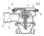
- Fig. 1 shows a section of an actuator 1 with a membrane 2, the outer Edge 3 is clamped between a housing and a cover flange 4 and 5 and the an existing control pressure chamber 7 in the cover 6 limits its control pressure via a housing and a cover channel 8 and 9 and one of both channels 8 and 9 connecting membrane edge recess 10 takes place.
- This control element 1 is suitable, for example, for a switching valve in the supply line for so-called Secondary air of an internal combustion engine provided and in by an air pump the exhaust is promoted.
- the pressure at the valve inlet that occurs when the pump is started is via the housing and cover channels 8 and 9 guided into the control pressure chamber 7, whereby the valve opens.
- groove recesses 11, 12 on both sides of the membrane edge 3 are arranged, in which case a membrane insert, for example made of metal, is to be provided would.
- the cover 6 can have a cover channel 9, which uses deep-drawing technology is molded into the cover flange 5.
Landscapes
- Engineering & Computer Science (AREA)
- General Engineering & Computer Science (AREA)
- Mechanical Engineering (AREA)
- Physics & Mathematics (AREA)
- Chemical & Material Sciences (AREA)
- Automation & Control Theory (AREA)
- General Physics & Mathematics (AREA)
- Health & Medical Sciences (AREA)
- Fluid Mechanics (AREA)
- Chemical Kinetics & Catalysis (AREA)
- Toxicology (AREA)
- Combustion & Propulsion (AREA)
- Exhaust Gas After Treatment (AREA)
- Fluid-Driven Valves (AREA)
- Measuring Fluid Pressure (AREA)
Abstract
Description
Hierzu ist es notwendig, daß der am Ventileinlaß herrschende Druck über einen Gehäuse- und einen Deckelflansch in eine Steuerdruckkammer geführt wird.
einen Schnitt durch ein Stellelement eines Schaltventils;
eine alternative Ausführung des Stellelements nach Fig. 1.
Claims (5)
- Stellelement mit einer Membrane, deren äußerer Rand zwischen einem Gehäuse- und einem Deckelflansch eingespannt ist und die eine im Deckel bestehende Steuerdruckkammer begrenzt, deren Steuerdruckbeaufschlagung über einen Gehäuse- und einen Deckelkanal sowie eine beide Kanäle verbindende Membranrandausnehmung erfolgt, dadurch gekennzeichnet, daß zwischen dem Gehäusekanal (8) und der Membranrandausnehmung (10) und dieser und dem Deckelkanal (9) umlaufende Nutausnehmungen (11, 12) angeordnet sind.
- Stellelement nach Anspruch 1, dadurch gekennzeichnet, daß die Nutausnehmungen (11, 12) in dem Gehäuseflansch (4) und dem Deckelflansch (5) angeordnet sind.
- Stellelement nach Anspruch 1, dadurch gekennzeichnet, daß die Nutausnehmungen (11, 12) beiderseits des Membranrandes (3) angeordnet sind.
- Stellelement nach Anspruch 1, dadurch gekennzeichnet, daß die Nutausnehmungen (11, 12) in dem Gehäuseflansch (4) und in der dem Deckel (6) zugewandten Seite des Membranrandes (3) angeordnet sind.
- Stellelement nach Anspruch 4, dadurch gekennzeichnet, daß der Deckel (6) einen Deckelkanal (9) aufweist, der in Tiefziehtechnik in den Deckelflansch (5) eingeformt ist.
Applications Claiming Priority (2)
| Application Number | Priority Date | Filing Date | Title |
|---|---|---|---|
| DE19954472 | 1999-11-12 | ||
| DE19954472A DE19954472A1 (de) | 1999-11-12 | 1999-11-12 | Stellelement |
Publications (3)
| Publication Number | Publication Date |
|---|---|
| EP1099832A2 true EP1099832A2 (de) | 2001-05-16 |
| EP1099832A3 EP1099832A3 (de) | 2003-07-02 |
| EP1099832B1 EP1099832B1 (de) | 2004-04-14 |
Family
ID=7928817
Family Applications (1)
| Application Number | Title | Priority Date | Filing Date |
|---|---|---|---|
| EP00116986A Expired - Lifetime EP1099832B1 (de) | 1999-11-12 | 2000-08-08 | Stellelement |
Country Status (2)
| Country | Link |
|---|---|
| EP (1) | EP1099832B1 (de) |
| DE (2) | DE19954472A1 (de) |
Citations (1)
| Publication number | Priority date | Publication date | Assignee | Title |
|---|---|---|---|---|
| DE4307798A1 (de) | 1993-03-12 | 1994-09-15 | Bosch Gmbh Robert | Kombiventil |
Family Cites Families (2)
| Publication number | Priority date | Publication date | Assignee | Title |
|---|---|---|---|---|
| GB2251918A (en) * | 1991-01-19 | 1992-07-22 | Ford Motor Co | Gas flow control valve |
| DE19702917A1 (de) * | 1997-01-28 | 1998-07-30 | Pierburg Ag | Ventil für eine Gasleitung |
-
1999
- 1999-11-12 DE DE19954472A patent/DE19954472A1/de not_active Withdrawn
-
2000
- 2000-08-08 EP EP00116986A patent/EP1099832B1/de not_active Expired - Lifetime
- 2000-08-08 DE DE50006053T patent/DE50006053D1/de not_active Expired - Lifetime
Patent Citations (1)
| Publication number | Priority date | Publication date | Assignee | Title |
|---|---|---|---|---|
| DE4307798A1 (de) | 1993-03-12 | 1994-09-15 | Bosch Gmbh Robert | Kombiventil |
Also Published As
| Publication number | Publication date |
|---|---|
| DE50006053D1 (de) | 2004-05-19 |
| DE19954472A1 (de) | 2001-05-17 |
| EP1099832A3 (de) | 2003-07-02 |
| EP1099832B1 (de) | 2004-04-14 |
Similar Documents
| Publication | Publication Date | Title |
|---|---|---|
| DE1576769C3 (de) | Einrichtung zur Nachverbrennung der Abgase von Brennkraftmaschinen | |
| DE102004044439B4 (de) | Abblaseventil für einen Turbolader | |
| WO2017016684A1 (de) | Vorrichtung zum abscheiden von öl, lüftungssystem, zylinderkopfhaube und verbrennungsmotor | |
| EP0740064A1 (de) | Abgasrückführsteuerventil | |
| EP1591641A2 (de) | Klappenanordnung im Flanschbereich eines Ansaugsystems einer Brennkraftmaschine | |
| DE102008050252B4 (de) | Ventilvorrichtung für Brennkraftmaschinen, insbesondere Sekundärluftventil | |
| EP1717501A1 (de) | Ventil | |
| DE2255297A1 (de) | Ventil fuer abgasleitungen von brennkraftmaschinen | |
| EP1099832B1 (de) | Stellelement | |
| EP1342907B1 (de) | Ventileinrichtung | |
| DE2556738A1 (de) | Ausfallsicheres entlastungsventil | |
| EP0897059A2 (de) | Heissgas-Kraftmaschine mit einem nockengesteuerten, schaftgeführten Einlassventil | |
| DE2627359A1 (de) | Sekundaerluft-zufuhrsystem fuer brennkraftmaschinen | |
| DE4208045B4 (de) | Ventil mit zwei Verschlussgliedern | |
| EP1462624B1 (de) | Sekundärluftventil | |
| DE19504348C5 (de) | Abgasrückführsteuerventil | |
| DE10332915B4 (de) | Abgasrückführsystem für eine selbstzündende Verbrennungskraftmaschine mit einem Turbolader | |
| WO2016102256A1 (de) | Ventil zur steuerung eines gasstroms, flüssigkeitsabscheider, entlüftungssystem und verbrennungsmotor mit einem derartigen ventil | |
| DE102014102524A1 (de) | Anordnung zur Befestigung eines Regelventils an einem Strömungskanalgehäuse eines Verbrennungsmotors | |
| DE102019202380A1 (de) | Brennkraftmaschine mit einem Abgaskrümmer und einem Abgasturbolader | |
| DE102019130776B3 (de) | Luftzuführsystem für eine Verbrennungskraftmaschine | |
| DE10148384A1 (de) | Sekundärluftventil | |
| DE3731594C1 (de) | Rueckschlagventil fuer eine Gasleitung | |
| DE102006020531B3 (de) | Verbrennungsmotor | |
| EP1138926B1 (de) | Luftansaugkanalsystem für eine Brennkraftmaschine |
Legal Events
| Date | Code | Title | Description |
|---|---|---|---|
| PUAI | Public reference made under article 153(3) epc to a published international application that has entered the european phase |
Free format text: ORIGINAL CODE: 0009012 |
|
| 17P | Request for examination filed |
Effective date: 20000808 |
|
| AK | Designated contracting states |
Kind code of ref document: A2 Designated state(s): AT BE CH CY DE DK ES FI FR GB GR IE IT LI LU MC NL PT SE |
|
| AX | Request for extension of the european patent |
Free format text: AL;LT;LV;MK;RO;SI |
|
| RAP1 | Party data changed (applicant data changed or rights of an application transferred) |
Owner name: PIERBURG GMBH |
|
| PUAL | Search report despatched |
Free format text: ORIGINAL CODE: 0009013 |
|
| AK | Designated contracting states |
Designated state(s): AT BE CH CY DE DK ES FI FR GB GR IE IT LI LU MC NL PT SE |
|
| AX | Request for extension of the european patent |
Extension state: AL LT LV MK RO SI |
|
| RIC1 | Information provided on ipc code assigned before grant |
Ipc: 7F 01N 3/22 A Ipc: 7F 16K 31/126 B Ipc: 7F 16K 15/16 B |
|
| GRAP | Despatch of communication of intention to grant a patent |
Free format text: ORIGINAL CODE: EPIDOSNIGR1 |
|
| GRAS | Grant fee paid |
Free format text: ORIGINAL CODE: EPIDOSNIGR3 |
|
| GRAA | (expected) grant |
Free format text: ORIGINAL CODE: 0009210 |
|
| AKX | Designation fees paid |
Designated state(s): DE FR GB IT |
|
| AK | Designated contracting states |
Kind code of ref document: B1 Designated state(s): DE FR GB IT |
|
| REG | Reference to a national code |
Ref country code: GB Ref legal event code: FG4D Free format text: NOT ENGLISH |
|
| REF | Corresponds to: |
Ref document number: 50006053 Country of ref document: DE Date of ref document: 20040519 Kind code of ref document: P |
|
| REG | Reference to a national code |
Ref country code: IE Ref legal event code: FG4D Free format text: GERMAN |
|
| GBT | Gb: translation of ep patent filed (gb section 77(6)(a)/1977) |
Effective date: 20040723 |
|
| REG | Reference to a national code |
Ref country code: IE Ref legal event code: FD4D |
|
| ET | Fr: translation filed | ||
| PLBE | No opposition filed within time limit |
Free format text: ORIGINAL CODE: 0009261 |
|
| STAA | Information on the status of an ep patent application or granted ep patent |
Free format text: STATUS: NO OPPOSITION FILED WITHIN TIME LIMIT |
|
| 26N | No opposition filed |
Effective date: 20050117 |
|
| PGFP | Annual fee paid to national office [announced via postgrant information from national office to epo] |
Ref country code: FR Payment date: 20060817 Year of fee payment: 7 |
|
| PGFP | Annual fee paid to national office [announced via postgrant information from national office to epo] |
Ref country code: GB Payment date: 20060824 Year of fee payment: 7 |
|
| GBPC | Gb: european patent ceased through non-payment of renewal fee |
Effective date: 20070808 |
|
| REG | Reference to a national code |
Ref country code: FR Ref legal event code: ST Effective date: 20080430 |
|
| PG25 | Lapsed in a contracting state [announced via postgrant information from national office to epo] |
Ref country code: FR Free format text: LAPSE BECAUSE OF NON-PAYMENT OF DUE FEES Effective date: 20070831 |
|
| PG25 | Lapsed in a contracting state [announced via postgrant information from national office to epo] |
Ref country code: GB Free format text: LAPSE BECAUSE OF NON-PAYMENT OF DUE FEES Effective date: 20070808 |
|
| PGFP | Annual fee paid to national office [announced via postgrant information from national office to epo] |
Ref country code: DE Payment date: 20091026 Year of fee payment: 10 |
|
| PGFP | Annual fee paid to national office [announced via postgrant information from national office to epo] |
Ref country code: IT Payment date: 20090826 Year of fee payment: 10 |
|
| PG25 | Lapsed in a contracting state [announced via postgrant information from national office to epo] |
Ref country code: IT Free format text: LAPSE BECAUSE OF NON-PAYMENT OF DUE FEES Effective date: 20100808 |
|
| REG | Reference to a national code |
Ref country code: DE Ref legal event code: R119 Ref document number: 50006053 Country of ref document: DE Effective date: 20110301 |
|
| PG25 | Lapsed in a contracting state [announced via postgrant information from national office to epo] |
Ref country code: DE Free format text: LAPSE BECAUSE OF NON-PAYMENT OF DUE FEES Effective date: 20110301 |