EP1098060A1 - Apparatus preventing loosening of window- or door-frames - Google Patents
Apparatus preventing loosening of window- or door-frames Download PDFInfo
- Publication number
- EP1098060A1 EP1098060A1 EP00440290A EP00440290A EP1098060A1 EP 1098060 A1 EP1098060 A1 EP 1098060A1 EP 00440290 A EP00440290 A EP 00440290A EP 00440290 A EP00440290 A EP 00440290A EP 1098060 A1 EP1098060 A1 EP 1098060A1
- Authority
- EP
- European Patent Office
- Prior art keywords
- panel
- frame
- blade
- heaving
- heaving device
- Prior art date
- Legal status (The legal status is an assumption and is not a legal conclusion. Google has not performed a legal analysis and makes no representation as to the accuracy of the status listed.)
- Withdrawn
Links
Images
Classifications
-
- E—FIXED CONSTRUCTIONS
- E06—DOORS, WINDOWS, SHUTTERS, OR ROLLER BLINDS IN GENERAL; LADDERS
- E06B—FIXED OR MOVABLE CLOSURES FOR OPENINGS IN BUILDINGS, VEHICLES, FENCES OR LIKE ENCLOSURES IN GENERAL, e.g. DOORS, WINDOWS, BLINDS, GATES
- E06B5/00—Doors, windows, or like closures for special purposes; Border constructions therefor
- E06B5/10—Doors, windows, or like closures for special purposes; Border constructions therefor for protection against air-raid or other war-like action; for other protective purposes
- E06B5/11—Doors, windows, or like closures for special purposes; Border constructions therefor for protection against air-raid or other war-like action; for other protective purposes against burglary
- E06B5/116—Arrangements preventing the removal of glazing panels
-
- E—FIXED CONSTRUCTIONS
- E06—DOORS, WINDOWS, SHUTTERS, OR ROLLER BLINDS IN GENERAL; LADDERS
- E06B—FIXED OR MOVABLE CLOSURES FOR OPENINGS IN BUILDINGS, VEHICLES, FENCES OR LIKE ENCLOSURES IN GENERAL, e.g. DOORS, WINDOWS, BLINDS, GATES
- E06B3/00—Window sashes, door leaves, or like elements for closing wall or like openings; Layout of fixed or moving closures, e.g. windows in wall or like openings; Features of rigidly-mounted outer frames relating to the mounting of wing frames
- E06B3/54—Fixing of glass panes or like plates
- E06B3/5409—Means for locally spacing the pane from the surrounding frame
Definitions
- the invention relates to an anti-heaving device for door, window, window or similar joinery, having an outer side and an inner side, and defined by at minus a fixed or movable frame inside which is embedded a panel, in particular a glazing, coming on the wall, on its side outside the door, window or the like, against a shoulder that includes said frame.
- the present invention will find its application in the field the manufacture of joinery such as doors, windows, display cases or the like and relates, more in particular, a device intended to prevent the heaving of a panel, in particular a glazing, out of sound frame.
- such a framework usually comprises, a shoulder against which bears the external side of said panel when placed in said frame. This last receives, in particular by clipping, a barrier capable of cooperating with the internal side of said panel to ensure immobilization and finalize the mounting of the latter in said frame.
- a panel under the effect of a strong wind, a panel, more particularly glazing, tends to deform and exert pressure on said barrier which is likely to become detached from the frame which results in a loosening of said panel.
- Such heaving can, also, to intervene because of the deliberate action of a sharpening during a break-in attempt.
- Another solution is to interpose, between the song end of said panel and the frame rebate, an angle reinforcement, associated with the latter, and comprising a wing perpendicular extending to the rear of said panel, on the side internal of the latter. It will be observed that the establishment of said angle requires maintaining a certain clearance between the edge edge of said panel and the frame rebate. To to hide the presence of this angle, the frame receives, still, a barrier against the rear of said panel.
- the glazing in the anterior solution presents relative mobility with respect to the support angle so that the heaving with respect to the latter remains possible.
- the present invention overcomes the disadvantages of state of the art devices through a new particularly clever anti-heaving device.
- the present invention relates to an anti-heaving device for door, window, display cabinet or similar, having an outer side and an inner side, and defined by at least one fixed or movable frame inside which is embedded a panel, in particular a glazing, coming in applies, on its outer side against a shoulder that has said frame, characterized in that said device is consisting of a pre-frame adopting the shape of at least one blade made integral, by gluing, of said panel, at the edge peripheral of the latter and on the internal side, said blade being extended on this internal side by at least one tab capable of secure said device to the frame.
- said fixing lug has an orifice for the passage of a fixing member, in particular a screw or the like, on the one hand, accessible from the side internal door or other and, on the other hand, intended for cooperate with said frame, in particular with a metal reinforcement that internally, the latter.
- a fixing member in particular a screw or the like
- said fixing lug comprises means for fixing, in particular of the clip-on type, capable of cooperating with additional fixing means that the frame of the door or the like.
- said fixing lug extends, from said blade, substantially perpendicular to the latter and to the plane of said panel, said fixing lug comprising a return at which said orifice is formed, this return extending, on the one hand, parallel to the plane of said panel and in a direction opposite to the latter, and, on the other hand, to the rear of the frame and on the inner side of the door or the like.
- An additional feature of the present invention relates to the fact that said blade comprises, at its free end, a return oriented towards said panel.
- said blade is completed by a wing extending, on the one hand, so perpendicular, from this blade, in one direction opposite to that of the bracket and, on the other hand, in direction of the external side of the door or other and at the level of edge edge of the peripheral border of said panel.
- this wing has a width greater than the thickness of said panel so that its free end protrudes from the front of said panel, on the outside of the door, or analogous, and constitutes a stop capable of cooperating with the shoulder of said frame.
- An additional feature concerns the fact that the free end of said wing has an extending return parallel to the plane of the panel.
- said pre-frame is defined by at least one section portion comprising, at minus, a blade and a mounting bracket.
- said device can be completed and concealed by a covering profile, in particular in the form of a barrier or the like, capable of cooperating with said frame, on the internal side of the door or the like.
- this profile covering also defines sealing means in periphery between said panel and its frame.
- the present invention therefore consists of a panel, in particular glazing, to which a frame and component is attached, with the latter, a set intended to be embedded in a frame.
- This assembly abuts against a located shoulder, at said frame, on the external side of the door.
- the panel on its internal side, is glued against a rendered blade integral with said frame. It is, therefore, carried out a lateral support of said panel.
- the device according to the invention ensures a effective multidirectional holding of said panel inside of the frame and prevents its release, involuntary under the effect strong or willful wind breaking in.
- This device allows, however, a voluntary withdrawal of said sign authorizing an authorized person to access, from the internal side of said panel, to the fixing member of said device on the frame. By removing said organ from fixing, it is possible to remove the panel-frame assembly out of its scope to proceed with its replacement.
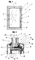
- Figure 1 is a schematic view in elevation of a door or the like comprising a frame in which is embedded a panel, the latter being associated with an anti-heaving device according to the invention.
- FIG. 2 corresponds to a schematic representation, partial and sectional view of the detail identified A in FIG. 1 and shows an anti-heaving device according to a first mode of production.
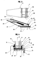
- FIG. 3 is a diagrammatic view, in perspective and in exploded, of the anti-heaving device shown in Figure 2.
- Figure 4 is a view similar to Figure 2 and corresponds to a second embodiment of an anti-heaving device.
- the present invention will find its application in the field the manufacture of joinery such as doors, windows, display cases or the like and relates, more in particular, a safety device able to equip these.
- such door 1, window or the like is usually present under the form of a sleeping frame 2 on which is mounted, articulated, a opening 3.
- the latter is usually defined by a frame 4 made of wood or resulting from the assembly of metal profiles 5 or synthetic material, and inside which is embedded a panel 6, in particular a glazing 7, extending in a plane P.
- the present invention also applies to a fixed frame such than a display case, which also has a frame inside which is embedded a panel defined by glazing.
- such a door 1 or other has an external side 8 as well as an internal side 9 oriented outward and inward, respectively of a building, a point of sale, a store or other equipped of such a door 1 or other.
- a panel 6 has been shown embedded in a frame 4.
- the latter comprises, on the outer side 8 of door 1 or other, a shoulder 10 against which said panel 6 is applied, especially when it is mounted in said frame 4.
- a shoulder 10 advantageously has a seal 11, attached to this frame 4 or coextruded with the latter, and coming to bear against said panel 6.
- the invention consists in that said door 1 or the like is fitted with a safety device 12 of the anti-heaving type, intended to oppose heaving, involuntary or maliciously, of panel 6 out of its frame 4 reception.
- Such an anti-heaving device 12 is, however, and advantageously, designed capable of allowing withdrawal voluntary, by an authorized operator, of said panel 6 outside of its frame 4, in particular with a view to its replacement.
- said anti-heaving device 12 is consisting of a frame 13 made integral, by gluing, of said panel 6, at the peripheral edge 14 of the latter and on the side internal 9 of door 1, window or the like.
- such a frame 13 has the shape of a blade 15 glued to said panel 6 and extended, on the internal side 9 of the door 1 or other, by at least one tab 16 intended to ensure fixing said anti-heaving device 12 to the frame 4.
- a tab attachment 16 extends, from said blade 15, to the rear said panel 6, on the internal side 9 of the door 1 or the like.
- said fixing lug 16 comprises fixing means suitable for cooperate with additional fixing means that presents said frame 4 of door 1 or other.
- Such fastening means can, for example, be of the type clip and / or step.
- said tab fixing 16 has an orifice 17 for the passage of a fixing member 18, in particular a screw or the like.
- said anti-heaving device 12 is designed in such a way that its attachment 18 can be accessible, for an authorized operator, on the internal side 9 of the door 1 or other, behind said panel 6.
- this fixing member 18 passes through said orifice 17 to cooperate with frame 4, in particular with a reinforcement metal 19 that internally comprises the latter.
- This blade 15 being glued to said panel 6, it extends in a plane substantially parallel to the plane P of said panel 6.
- said fixing lug 16 extends in a plane substantially perpendicular to that P of said panel 6 and, as visible in FIGS. 2 and 4, is preferably located in rebate 20 of said frame 4.
- said orifice 18 is formed directly at the level of said fixing lug 16 extending substantially perpendicular to plane P of panel 6, in particular in rebate of frame 4.
- said fixing lug 16 has a return 21 extending from of the free end 22 of said fixing lug 16, of parallel to the plane P of said panel 6, and in a opposite direction to the latter.
- a return 21 comes position at the rear of the frame 4, in particular against this last, and on the inner side 9 of the door or the like. It is, more particularly, at the level of this return 21 which is provided said orifice 17.
- the blade 15 of the anti-heaving device 12 has a free end 23 provided with an oriented return 24, in particular so perpendicular, towards said panel 6.
- Such a return 24 is designed, on the one hand, capable of ensuring a spacing 25 between panel 6 and blade 15 of the device anti-heaving 12, in this spacing 25 coming to take places a bead of glue 26 capable of ensuring the bonding of said blade 15 on the panel 6.
- This return 24 is, on the other hand, designed suitable for retaining the adhesive of the cord 26 so as to avoid its flow, in particular during the installation of said blade 15 on panel 6.
- Another characteristic of the present invention relates to the fact that said blade 15 is completed by a wing 27 extending perpendicularly from this blade 15, in a direction opposite to the fixing lug 16.
- said wing 27 is made integral with said panel 6, in particular through a portion of the adhesive bead 26. This portion ensures the bonding end edge 28 of said panel 6 on wing 27 of anti-heaving device 12.
- said wing 27 has a width 29 greater than the thickness 30 of said panel 6, if necessary corrected for spacing 25. Also, after the installation of said anti-heaving device 12 on the panel 6, said wing 27 extends in direction of the external side 8 of the door 1 or the like and has a free end 31 projecting from the front of said panel 6. As visible in FIG. 4, this free end 31 advantageously defines a stop capable of cooperating with the shoulder 10 of said frame 4 in order to guarantee the positioning, inside the latter 4, of said panel 6.
- FIG. 3 corresponding to a view exploded view of the panel 6 and of the anti-heaving device 12, before the installation of the latter at the edge peripheral 14 of said panel 6.
- the bead of glue 26 is located at the level of the blade 15 and / or of the wing 27.
- This the latter is supplemented by means 32 capable of ensuring spacing between the latter and the end edge 28 of said panel 6, this in order to allow the establishment of a appropriate amount of glue, suitable for fixing effective of the panel 6 on said wing 27, while avoiding its evacuation by crushing.
- Such means 32 can be constituted by a suitable shim.
- the free end 31 of said wing 27 can advantageously be fitted with a return 33 extending parallel to the plane P of said panel 6 and direction of the latter.
- Said return 33 is, in fact, designed suitable for retaining the adhesive of the cord 26 so as to avoid flow, at the free end 31 of said wing 27, likely to cause sticking of the anti-heaving device 12 on frame 4.
- an anti-heaving device 12 adopting the shape of a profile 34, in particular in aluminum, extending over the entire length of the panel 6 to equip. It is obvious that the present invention is not in no way limited to such an embodiment and that such anti-heaving device 12 can be in the form at least one section of profile, associated with said panel 6, and comprising, at least, a blade 15 as well as a fixing lug 16.
- the latter 16 may in fact be in the form a wing 35 extending at the rear of said blade 15 or else like one or more tabs.
- anti-heaving device 12 can also be completed with a covering profile 36, associated with said frame 4, located on the internal side 9 of door 1 or the like and behind said panel 6.
- Such a covering profile 36 makes it possible to conceal the presence of said anti-heaving device 12 and adopts, for example, the form of a barrier 37 or the like.
- this trim profile further defines sealing means at the periphery between said panel 6 and its frame 4.
Abstract
Description
L'invention a trait à un dispositif anti-déchaussement pour menuiserie de type porte, fenêtre, vitrine ou analogue, comportant un côté externe et un côté interne, et définie par au moins un cadre fixe ou mobile à l'intérieur duquel est enchâssé un panneau, notamment un vitrage, venant en applique, sur son côté externe à la porte, fenêtre ou analogue, contre un épaulement que comporte ledit cadre.The invention relates to an anti-heaving device for door, window, window or similar joinery, having an outer side and an inner side, and defined by at minus a fixed or movable frame inside which is embedded a panel, in particular a glazing, coming on the wall, on its side outside the door, window or the like, against a shoulder that includes said frame.
La présente invention trouvera son application dans le domaine de la fabrication de menuiseries telles que des portes, fenêtres, vitrines ou analogues et concerne, plus particulièrement, un dispositif destiné à empêcher le déchaussement d'un panneau, notamment un vitrage, hors de son cadre.The present invention will find its application in the field the manufacture of joinery such as doors, windows, display cases or the like and relates, more in particular, a device intended to prevent the heaving of a panel, in particular a glazing, out of sound frame.
L'on connaít, d'ores et déjà, des menuiseries comportant un cadre résultant, usuellement, de l'assemblage de profilés et, dans lequel est enchâssé un panneau, notamment un vitrage.We already know carpentry with a frame usually resulting from the assembly of profiles and, in which is embedded a panel, in particular a glazing.
A ce propos, on observera qu'un tel cadre comporte, usuellement, un épaulement contre lequel prend appui le côté externe dudit panneau lors de sa mise en place dans ledit cadre. Ce dernier reçoit, notamment par clipage, une pare-close apte à coopérer avec le côté interne dudit panneau pour assurer l'immobilisation et finaliser le montage de ce dernier dans ledit cadre.In this regard, it will be observed that such a framework usually comprises, a shoulder against which bears the external side of said panel when placed in said frame. This last receives, in particular by clipping, a barrier capable of cooperating with the internal side of said panel to ensure immobilization and finalize the mounting of the latter in said frame.
Il convient d'observer que, sous l'effet d'un vent fort, un panneau, plus particulièrement un vitrage, a tendance à se déformer et exerce une pression sur ladite pare-close qui est susceptible de se désolidariser du cadre ce qui se traduit par un déchaussement dudit panneau. Un tel déchaussement peut, également, intervenir du fait de l'action délibérée d'un aigrefin au cours d'une tentative d'effraction. It should be noted that, under the effect of a strong wind, a panel, more particularly glazing, tends to deform and exert pressure on said barrier which is likely to become detached from the frame which results in a loosening of said panel. Such heaving can, also, to intervene because of the deliberate action of a sharpening during a break-in attempt.
Afin de remédier à ce problème de déchaussement, il a été imaginé d'interposer un cordon de colle entre l'épaulement du cadre et ledit panneau. Ceci permet de résoudre efficacement le problème du déchaussement mais entraíne un certain nombre de nouveaux problèmes, notamment lorsqu'il s'agit de procéder au remplacement dudit panneau car, pour ce faire, il est nécessaire de découper ledit cordon de colle.In order to remedy this heaving problem, it was imagined to interpose a bead of glue between the shoulder of the frame and said panel. This effectively resolves the heaving problem but causes a number of new problems, especially when it comes to replacement of said panel because, to do this, it is necessary to cut said bead of glue.
A ce propos, on observera qu'un tel cordon est, généralement, complété par un joint d'étanchéité, là encore interposé entre le cadre et ledit panneau, et venant en appui contre ce dernier. Aussi, lors du découpage du cordon de colle, il est fréquent d'entailler ledit joint qui demande, alors, à être remplacé. Un tel remplacement peut être, soit envisageable, mais onéreux, lorsque ledit joint est de nature interchangeable, soit impossible lorsqu'un tel joint est obtenu par coextrusion avec le profilé définissant ledit cadre.In this regard, it will be observed that such a cord is, generally, completed by a seal, again interposed between the frame and said panel, and coming to bear against the latter. Also, when cutting the bead of glue, it is common to score said seal which then needs to be replaced. A such a replacement can be either possible, but expensive, when said seal is of an interchangeable nature, either impossible when such a joint is obtained by coextrusion with the profile defining said frame.
De plus, dans le cas particulier d'un châssis fixe non démontable pour assurer la fixation du nouveau panneau, il convient de mettre en place un nouveau cordon de colle qui a tendance à couler, notamment sous ledit panneau, ce qui réduit fortement toute possibilité de remplacement ultérieur de ce dernier.In addition, in the particular case of a fixed chassis not removable to secure the new panel, it should install a new bead of glue which has tendency to sink, especially under said panel, which reduces strongly any possibility of subsequent replacement of this latest.
Une autre solution consiste à interposer, entre le chant d'extrémité dudit panneau et la feuillure du cadre, une cornière de renfort, associée à ce dernier, et comportant une aile perpendiculaire s'étendant à l'arrière dudit panneau, du côté interne de ce dernier. On observera que la mise en place de ladite cornière nécessite de préserver un certain jeu entre le chant d'extrémité dudit panneau et la feuillure du cadre. Afin d'occulter la présence de cette cornière, le cadre reçoit, encore, une pare-close disposée à l'arrière dudit panneau. Another solution is to interpose, between the song end of said panel and the frame rebate, an angle reinforcement, associated with the latter, and comprising a wing perpendicular extending to the rear of said panel, on the side internal of the latter. It will be observed that the establishment of said angle requires maintaining a certain clearance between the edge edge of said panel and the frame rebate. To to hide the presence of this angle, the frame receives, still, a barrier against the rear of said panel.
Cette solution autorise un maintien latéral dudit panneau, ce dernier n'étant, cependant, aucunement maintenu dans le plan de la vitre du fait de la présence d'un jeu entre le panneau et la feuillure. Aussi, lors d'une tentative d'effraction, un malandrin est susceptible de soulever ledit panneau et d'en assurer le déchaussement, hors de ladite cornière.This solution allows lateral support of said panel, this the latter being, however, in no way maintained in the plan of the glass due to the presence of a clearance between the panel and the rabbet. Also, during a break-in attempt, a malandrin is likely to lift said panel and provide heaving, out of said angle.
Un tel inconvénient se retrouve, par exemple, dans le mode de réalisation tel que décrit dans le document DE-U-298 11 261.Such a drawback is found, for example, in the mode of realization as described in document DE-U-298 11 261.
En particulier, il s'agit d'une simple cornière qui, une fois le vitrage d'une porte, fenêtre ou similaire disposé dans son cadre, comporte une aile venant en applique du côté interne de ce vitrage, tandis que l'aile qui lui est perpendiculaire et qui s'étend du côté interne à l'habitation est perforée d'orifices pour le passage de vis de fixation venant se loger dans l'épaisseur de ce cadre. En particulier, lorsque celui-ci est conçu en PVC et comporte, intérieurement, un renfort métallique, les vis de fixation, préférentiellement du type auto-perçantes, sont définies aptes à venir en prise avec ce renfort métallique.In particular, it is a simple angle which, once the glazing of a door, window or the like arranged in its frame, has a wing that comes to apply on the internal side of this glazing, while the wing which is perpendicular to it and which extends from the internal side to the dwelling is perforated with orifices for the passage of fixing screws coming to be housed in the thickness of this frame. In particular, when this is designed in PVC and includes, internally, a metal reinforcement, the fixing screws, preferably of the self-piercing type, are defined capable of engaging with this metallic reinforcement.
Par conséquent, le vitrage dans la solution antérieure, présente une mobilité relative par rapport à la cornière de maintien de sorte que le déchaussement par rapport à cette dernière reste possible.Therefore, the glazing in the anterior solution, presents relative mobility with respect to the support angle so that the heaving with respect to the latter remains possible.
La présente invention permet de remédier aux inconvénients des dispositifs de l'état de la technique au travers d'un nouveau dispositif anti-déchaussement particulièrement astucieux.The present invention overcomes the disadvantages of state of the art devices through a new particularly clever anti-heaving device.
A cet effet, la présente invention concerne un dispositif anti-déchaussement pour menuiserie de type porte, fenêtre, vitrine ou analogue, comportant un côté externe et un côté interne, et définie par au moins un cadre fixe ou mobile à l'intérieur duquel est enchâssé un panneau, notamment un vitrage, venant en applique, sur son côté externe contre un épaulement que comporte ledit cadre, caractérisé par le fait que ledit dispositif est constitué par un précadre adoptant la forme d'au moins une lame rendue solidaire, par collage, dudit panneau, en bordure périphérique de ce dernier et du côté interne, ladite lame étant prolongée de ce côté interne par au moins une patte apte à assurer la fixation dudit dispositif sur le cadre.To this end, the present invention relates to an anti-heaving device for door, window, display cabinet or similar, having an outer side and an inner side, and defined by at least one fixed or movable frame inside which is embedded a panel, in particular a glazing, coming in applies, on its outer side against a shoulder that has said frame, characterized in that said device is consisting of a pre-frame adopting the shape of at least one blade made integral, by gluing, of said panel, at the edge peripheral of the latter and on the internal side, said blade being extended on this internal side by at least one tab capable of secure said device to the frame.
Selon une autre caractéristique, ladite patte de fixation comporte un orifice pour le passage d'un organe de fixation, notamment une vis ou analogue, d'une part, accessible du côté interne de la porte ou autre et, d'autre part, destiné à coopérer avec ledit cadre, notamment avec un renfort métallique que comporte, intérieurement, ce dernier.According to another characteristic, said fixing lug has an orifice for the passage of a fixing member, in particular a screw or the like, on the one hand, accessible from the side internal door or other and, on the other hand, intended for cooperate with said frame, in particular with a metal reinforcement that internally, the latter.
Une autre caractéristique de la présente invention concerne le fait que ladite patte de fixation comporte des moyens de fixation, notamment du type à cliper, aptes à coopérer avec des moyens de fixation complémentaires que comporte le cadre de la porte ou analogue.Another characteristic of the present invention relates to the the fact that said fixing lug comprises means for fixing, in particular of the clip-on type, capable of cooperating with additional fixing means that the frame of the door or the like.
Une caractéristique additionnelle concerne le fait que ledit orifice est ménagé au niveau d'une patte de fixation s'étendant, à partir de ladite lame, de manière sensiblement perpendiculaire à cette dernière et au plan dudit panneau, en feuillure du cadre.An additional characteristic concerns the fact that said orifice is provided at the level of an extending fixing tab, from said blade, substantially perpendicularly to the latter and to the plane of the said panel, in the rebate of the frame.
Selon une autre caractéristique, ladite patte de fixation s'étend, à partir de ladite lame, de manière sensiblement perpendiculaire à cette dernière et au plan dudit panneau, ladite patte de fixation comportant un retour au niveau duquel est ménagé ledit orifice, ce retour s'étendant, d'une part, parallèlement au plan dudit panneau et dans une direction opposée à ce dernier, et, d'autre part, à l'arrière du cadre et du côté interne de la porte ou analogue. According to another characteristic, said fixing lug extends, from said blade, substantially perpendicular to the latter and to the plane of said panel, said fixing lug comprising a return at which said orifice is formed, this return extending, on the one hand, parallel to the plane of said panel and in a direction opposite to the latter, and, on the other hand, to the rear of the frame and on the inner side of the door or the like.
Une caractéristique additionnelle de la présente invention concerne le fait que ladite lame comporte, au niveau de son extrémité libre, un retour orienté en direction dudit panneau.An additional feature of the present invention relates to the fact that said blade comprises, at its free end, a return oriented towards said panel.
Selon une caractéristique additionnelle, ladite lame est complétée par une aile s'étendant, d'une part, de manière perpendiculaire, à partir de cette lame, dans une direction opposée à celle de la patte de fixation et, d'autre part, en direction du côté externe de la porte ou autre et au niveau du chant d'extrémité de la bordure périphérique dudit panneau.According to an additional characteristic, said blade is completed by a wing extending, on the one hand, so perpendicular, from this blade, in one direction opposite to that of the bracket and, on the other hand, in direction of the external side of the door or other and at the level of edge edge of the peripheral border of said panel.
En fait, cette aile présente une largeur supérieure à l'épaisseur dudit panneau de sorte que son extrémité libre dépasse à l'avant dudit panneau, du côté externe de la porte ou analogue, et constitue une butée apte à coopérer avec l'épaulement dudit cadre.In fact, this wing has a width greater than the thickness of said panel so that its free end protrudes from the front of said panel, on the outside of the door, or analogous, and constitutes a stop capable of cooperating with the shoulder of said frame.
Une caractéristique additionnelle concerne le fait que l'extrémité libre de ladite aile comporte un retour s'étendant parallèlement au plan du panneau.An additional feature concerns the fact that the free end of said wing has an extending return parallel to the plane of the panel.
Selon une autre caractéristique dudit dispositif, ledit précadre est défini par au moins une portion de profilé comportant, au moins, une lame ainsi qu'une patte de fixation.According to another characteristic of said device, said pre-frame is defined by at least one section portion comprising, at minus, a blade and a mounting bracket.
Finalement, ledit dispositif peut être complété et occulté par un profilé d'habillage, notamment sous la forme d'une pare-close ou analogue, apte à coopérer avec ledit cadre, du côté interne de la porte ou analogue. Préférentiellement, ce profilé d'habillage définit, en outre, des moyens d'étanchéité en périphérie entre ledit panneau et son cadre.Finally, said device can be completed and concealed by a covering profile, in particular in the form of a barrier or the like, capable of cooperating with said frame, on the internal side of the door or the like. Preferably, this profile covering also defines sealing means in periphery between said panel and its frame.
La présente invention consiste, donc, en un panneau, notamment un vitrage, sur lequel est rapporté un précadre et constituant, avec ce dernier, un ensemble destiné à être enchâssé dans un cadre. Cet ensemble vient en butée contre un épaulement situé, au niveau dudit cadre, du côté externe de la porte. Le panneau, au niveau de son côté interne, est collé contre une lame rendue solidaire dudit cadre. Il est, par conséquent, réalisé un maintien latéral dudit panneau.The present invention therefore consists of a panel, in particular glazing, to which a frame and component is attached, with the latter, a set intended to be embedded in a frame. This assembly abuts against a located shoulder, at said frame, on the external side of the door. The panel, on its internal side, is glued against a rendered blade integral with said frame. It is, therefore, carried out a lateral support of said panel.
De plus, le fait, d'une part, de coller ledit panneau sur ledit dispositif anti-déchaussement et, d'autre part, de fixer ce dernier sur le cadre permet, avantageusement, de maintenir ledit panneau dans son plan.In addition, the fact, on the one hand, of sticking said panel on said anti-heaving device and, on the other hand, to fix this last on the frame advantageously allows to maintain said panel in his plan.
Ainsi, le dispositif selon l'invention permet d'assurer un maintien multidirectionnel efficace dudit panneau à l'intérieur du cadre et empêche son déchaussement, involontaire sous l'effet d'un vent fort ou volontaire par effraction.Thus, the device according to the invention ensures a effective multidirectional holding of said panel inside of the frame and prevents its release, involuntary under the effect strong or willful wind breaking in.
Ce dispositif permet, cependant, un retrait volontaire dudit panneau en autorisant, à une personne habilitée, un accès, à partir du côté interne dudit panneau, à l'organe de fixation dudit dispositif sur le cadre. En retirant ledit organe de fixation, il est possible de sortir l'ensemble panneau-précadre hors de son cadre pour procéder à son remplacement.This device allows, however, a voluntary withdrawal of said sign authorizing an authorized person to access, from the internal side of said panel, to the fixing member of said device on the frame. By removing said organ from fixing, it is possible to remove the panel-frame assembly out of its scope to proceed with its replacement.
D'autres buts et avantages de la présente invention apparaítront au cours de la description qui va suivre dont la compréhension sera facilitée en se référant aux dessins joints en annexe.Other objects and advantages of the present invention will become apparent during the description which follows whose understanding will be facilitated by referring to the attached drawings.
La figure 1 est une vue schématisée et en élévation d'une porte ou analogue comportant un cadre dans lequel est enchâssé un panneau, ce dernier étant associé à un dispositif anti-déchaussement selon l'invention.Figure 1 is a schematic view in elevation of a door or the like comprising a frame in which is embedded a panel, the latter being associated with an anti-heaving device according to the invention.
La figure 2 correspond à une représentation schématisée, partielle et en coupe du détail identifié A sur la figure 1 et montre un dispositif anti-déchaussement selon un premier mode de réalisation. FIG. 2 corresponds to a schematic representation, partial and sectional view of the detail identified A in FIG. 1 and shows an anti-heaving device according to a first mode of production.
La figure 3 est une vue schématisée, en perspective et en éclaté, du dispositif anti-déchaussement représenté figure 2.FIG. 3 is a diagrammatic view, in perspective and in exploded, of the anti-heaving device shown in Figure 2.
La figure 4 est une vue similaire à figure 2 et correspond à un second mode de réalisation d'un dispositif anti-déchaussement.Figure 4 is a view similar to Figure 2 and corresponds to a second embodiment of an anti-heaving device.
La présente invention trouvera son application dans le domaine de la fabrication des menuiseries telles que des portes, fenêtres, vitrines ou analogues et concerne, plus particulièrement, un dispositif de sécurité apte à équiper celles-ci.The present invention will find its application in the field the manufacture of joinery such as doors, windows, display cases or the like and relates, more in particular, a safety device able to equip these.
Tel que visible sur la figure 1 du dessin en annexe, une telle
porte 1, fenêtre ou analogue se présente, usuellement, sous la
forme d'un cadre dormant 2 sur lequel est monté, articulé, un
ouvrant 3. Ce dernier est défini, habituellement, par un cadre 4
en bois ou résultant de l'assemblage de profilés 5 métalliques
ou en matière synthétique, et à l'intérieur duquel est enchâssé
un panneau 6, notamment un vitrage 7, s'étendant dans un plan P.As shown in Figure 1 of the accompanying drawing, such
door 1, window or the like is usually present under the
form of a
Si, dans la suite de la description, il sera, plus particulièrement, fait référence à une porte 1 ou analogue, la présente invention s'applique, également, à un châssis fixe tel qu'une vitrine comportant, elle aussi, un cadre à l'intérieur duquel est enchâssé un panneau défini par un vitrage.If, in the following description, it will be more particularly, refers to a door 1 or the like, the present invention also applies to a fixed frame such than a display case, which also has a frame inside which is embedded a panel defined by glazing.
Tel que visible sur les figures 2 et 4, une telle porte 1 ou
autre présente un côté externe 8 ainsi qu'un côté interne 9
orientés, respectivement, vers l'extérieur et vers l'intérieur
d'un bâtiment, d'un point de vente, d'un magasin ou autre équipé
d'une telle porte 1 ou autre.As shown in Figures 2 and 4, such a door 1 or
other has an external side 8 as well as an
Sur ces mêmes figures, il a été représenté un panneau 6 enchâssé
dans un cadre 4. Ce dernier comporte, sur le côté externe 8 de
la porte 1 ou autre, un épaulement 10 contre lequel ledit
panneau 6 vient en applique, notamment lors de son montage dans
ledit cadre 4. Un tel épaulement 10 présente, avantageusement,
un joint d'étanchéité 11, rapporté sur ce cadre 4 ou coextrudé
avec ce dernier, et venant en applique contre ledit panneau 6.In these same figures, a
L'invention consiste en ce que ladite porte 1 ou analogue est
équipée d'un dispositif de sécurité 12 du type anti-déchaussement,
destiné à s'opposer au déchaussement,
involontaire ou par malveillance, du panneau 6 hors de son cadre
4 de réception.The invention consists in that said door 1 or the like is
fitted with a
Un tel dispositif anti-déchaussement 12 est, cependant et de
manière avantageuse, conçu apte à permettre le retrait
volontaire, par un opérateur autorisé, dudit panneau 6 hors de
son cadre 4, notamment en vue de son remplacement.Such an
Selon l'invention, ledit dispositif anti-déchaussement 12 est
constitué par un précadre 13 rendu solidaire, par collage, dudit
panneau 6, en bordure périphérique 14 de ce dernier et du côté
interne 9 de la porte 1, fenêtre ou analogue.According to the invention, said
D'ores et déjà, il y a lieu de préciser que la notion de précadre doit être vue dans un sens très large puisque, comme cela ressortira de la description qui va suivre, le précadre, objet de l'invention, peut se résumer à de simples tronçons de profilés, de longueur réduite, collés en périphérie sur le panneau 4.It should already be pointed out that the concept of precadre must be seen in a very broad sense since, as this will emerge from the description which follows, the preceding box, object of the invention can be summarized in simple sections of profiles, of reduced length, glued on the periphery on the panel 4.
En fait, un tel précadre 13 présente la forme d'une lame 15
collée sur ledit panneau 6 et prolongée, du côté interne 9 de la
porte 1 ou autre, par au moins une patte 16 destinée à assurer
la fixation dudit dispositif anti-déchaussement 12 sur le cadre
4. Tel que visible sur les figures 2 et 4, une telle patte de
fixation 16 s'étend, à partir de ladite lame 15, à l'arrière
dudit panneau 6, du côté interne 9 de la porte 1 ou autre. In fact, such a
Selon un premier mode de réalisation non représenté, ladite
patte de fixation 16 comporte des moyens de fixation aptes à
coopérer avec des moyens de fixation complémentaires que
présente ledit cadre 4 de la porte 1 ou autre.According to a first embodiment not shown, said
De tels moyens de fixation peuvent, par exemple, être du type à cliper et/ou à redans.Such fastening means can, for example, be of the type clip and / or step.
Cependant et selon un mode de réalisation préféré, ladite patte
de fixation 16 comporte un orifice 17 pour le passage d'un
organe de fixation 18, notamment une vis ou analogue.However and according to a preferred embodiment, said
Tel que visible sur les figures 2 et 4, ledit dispositif anti-déchaussement
12 est conçu de telle sorte que son organe de
fixation 18 puisse être accessible, pour un opérateur autorisé,
du côté interne 9 de la porte 1 ou autre, à l'arrière dudit
panneau 6.As shown in Figures 2 and 4, said
En fait, cet organe de fixation 18 traverse ledit orifice 17
pour venir coopérer avec le cadre 4, notamment avec un renfort
métallique 19 que comporte, intérieurement, ce dernier.In fact, this fixing
On observera qu'une telle coopération autorise une
immobilisation dudit panneau 6 par rapport à son cadre 4 et
empêche, tout particulièrement et de manière avantageuse, tout
mouvement dudit panneau 6 dans son plan P.It will be observed that such cooperation authorizes a
immobilization of said
En ce qui concerne, plus particulièrement, ladite patte de
fixation 16, celle-ci s'étend à partir de ladite lame 15, de
manière sensiblement perpendiculaire à cette dernière, à
l'arrière dudit panneau 6 et du côté interne 9 de la porte 1 ou
autre.With regard, more particularly, to said
Cette lame 15 étant collée sur ledit panneau 6, elle s'étend
dans un plan sensiblement parallèle au plan P dudit panneau 6.
Il en résulte que ladite patte de fixation 16 s'étend dans un
plan sensiblement perpendiculaire à celui P dudit panneau 6 et,
tel que visible figure 2 et 4, se situe, de préférence, en
feuillure 20 dudit cadre 4.This
Selon un premier mode de réalisation représenté figures 2 et 3,
ledit orifice 18 est ménagé directement au niveau de ladite
patte de fixation 16 s'étendant de manière sensiblement
perpendiculaire au plan P du panneau 6, notamment en feuillure
du cadre 4.According to a first embodiment shown in FIGS. 2 and 3,
said
Selon un autre mode de réalisation représenté figure 4, ladite
patte de fixation 16 comporte un retour 21 s'étendant, à partir
de l'extrémité libre 22 de ladite patte de fixation 16, de
manière parallèle au plan P dudit panneau 6, et dans une
direction opposée à ce dernier. En fait, un tel retour 21 vient
se positionner à l'arrière du cadre 4, notamment contre ce
dernier, et du côté interne 9 de la porte ou analogue. C'est,
plus particulièrement, au niveau de ce retour 21 qu'est ménagé
ledit orifice 17.According to another embodiment shown in Figure 4, said
fixing
Selon une caractéristique additionnelle de la présente invention
et tel que visible sur les figures 2 à 4, la lame 15 du
dispositif anti-déchaussement 12 présente une extrémité libre 23
pourvue d'un retour 24 orienté, notamment de manière
perpendiculaire, en direction dudit panneau 6.According to an additional feature of the present invention
and as visible in FIGS. 2 to 4, the
Un tel retour 24 est conçu, d'une part, apte à assurer un
espacement 25 entre le panneau 6 et la lame 15 du dispositif
anti-déchaussement 12, dans cet espacement 25 venant prendre
place un cordon de colle 26 apte à assurer le collage de ladite
lame 15 sur le panneau 6. Ce retour 24 est, d'autre part, conçu
apte à retenir la colle du cordon 26 de manière à éviter son
écoulement, notamment lors de la mise en place de ladite lame 15
sur le panneau 6.Such a
Une autre caractéristique de la présente invention concerne le
fait que ladite lame 15 est complétée par une aile 27
s'étendant, de manière perpendiculaire, à partir de cette lame
15, dans une direction opposée à la patte de fixation 16. En
fait, cette aile 27, après la mise en place dudit dispositif
anti-déchaussement 12 sur le panneau 6, s'étend en direction du
côté externe 8 de la porte 1 ou autre et au niveau du chant
d'extrémité 28 de la bordure périphérique 14 dudit panneau 6.Another characteristic of the present invention relates to the
the fact that said
Tel que visible sur les figures 2 et 4, ladite aile 27 est
rendue solidaire dudit panneau 6, notamment au travers d'une
portion du cordon de colle 26. Cette portion assure le collage
du chant d'extrémité 28 dudit panneau 6 sur l'aile 27 du
dispositif anti-déchaussement 12.As shown in Figures 2 and 4, said
Selon un mode de réalisation préféré de la présente invention,
ladite aile 27 présente une largeur 29 supérieure à l'épaisseur
30 dudit panneau 6, le cas échéant corrigée de l'espacement 25.
Aussi, après la mise en place dudit dispositif anti-déchaussement
12 sur le panneau 6, ladite aile 27 s'étend en
direction du côté externe 8 de la porte 1 ou analogue et
présente une extrémité libre 31 dépassant à l'avant dudit
panneau 6. Tel que visible figure 4, cette extrémité libre 31
définit, avantageusement, une butée apte à coopérer avec
l'épaulement 10 dudit cadre 4 en vue de garantir le
positionnement, à l'intérieur de ce dernier 4, dudit panneau 6.According to a preferred embodiment of the present invention,
said
L'on se réfère, à présent, à la figure 3 correspondant à une vue
en éclaté du panneau 6 et du dispositif anti-déchaussement 12,
avant la mise en place de ce dernier au niveau de la bordure
périphérique 14 dudit panneau 6.Reference is now made to FIG. 3 corresponding to a view
exploded view of the
Sur cette figure 3, l'on observera que le cordon de colle 26 est
localisé au niveau de la lame 15 et/ou de l'aile 27. Cette
dernière est complétée par des moyens 32 aptes à assurer un
espacement entre celle-ci et le chant d'extrémité 28 dudit
panneau 6, ceci en vue de permettre la mise en place d'une
quantité appropriée de colle, apte à assurer une fixation
efficace du panneau 6 sur ladite aile 27, tout en évitant son
évacuation par écrasement. De tels moyens 32 peuvent être
constitués par une cale adaptée.In this FIG. 3, it will be observed that the bead of
Comme visible sur la figure 4, l'extrémité libre 31 de ladite
aile 27 peut, avantageusement, être équipée d'un retour 33
s'étendant parallèlement au plan P dudit panneau 6 et en
direction de ce dernier. Ledit retour 33 est, en fait, conçu
apte à retenir la colle du cordon 26 de manière à éviter un
écoulement, au niveau de l'extrémité libre 31 de ladite aile 27,
susceptible d'occasionner le collage du dispositif anti-déchaussement
12 sur le cadre 4.As shown in Figure 4, the
Sur cette figure 3, il a été représenté un dispositif anti-déchaussement
12 adoptant la forme d'un profilé 34, notamment en
aluminium, s'étendant sur toute la longueur du panneau 6 à
équiper. Il est évident que la présente invention n'est
nullement limitée à un tel mode de réalisation et qu'un tel
dispositif anti-déchaussement 12 peut se présenter sous la forme
d'au moins un tronçon de profilé, associé audit panneau 6, et
comportant, au moins, une lame 15 ainsi qu'une patte de fixation
16.In this figure 3, there is shown an
Cette dernière 16 peut, en fait, se présenter sous la forme
d'une aile 35 s'étendant à l'arrière de ladite lame 15 ou encore
comme une ou plusieurs languettes.The latter 16 may in fact be in the form
a
Finalement le dispositif anti-déchaussement 12 selon l'invention
peut, encore, être complété par un profilé d'habillage 36,
associé audit cadre 4, implanté du côté interne 9 de la porte 1
ou analogue et à l'arrière dudit panneau 6.Finally the
Un tel profilé d'habillage 36 permet d'occulter la présence
dudit dispositif anti-déchaussement 12 et adopte, par exemple,
la forme d'un pare-close 37 ou analogue. Such a
Préférentiellement, ce profilé d'habillage définit, en outre,
des moyens d'étanchéité en périphérie entre ledit panneau 6 et
son cadre 4.Preferably, this trim profile further defines
sealing means at the periphery between said
Claims (12)
Applications Claiming Priority (2)
| Application Number | Priority Date | Filing Date | Title |
|---|---|---|---|
| FR9914088 | 1999-11-05 | ||
| FR9914088A FR2800793B1 (en) | 1999-11-05 | 1999-11-05 | ANTI-SLIPPING DEVICE FOR DOOR, WINDOW, SHOWCASE OR THE LIKE JOINERY |
Publications (1)
| Publication Number | Publication Date |
|---|---|
| EP1098060A1 true EP1098060A1 (en) | 2001-05-09 |
Family
ID=9551925
Family Applications (1)
| Application Number | Title | Priority Date | Filing Date |
|---|---|---|---|
| EP00440290A Withdrawn EP1098060A1 (en) | 1999-11-05 | 2000-10-27 | Apparatus preventing loosening of window- or door-frames |
Country Status (2)
| Country | Link |
|---|---|
| EP (1) | EP1098060A1 (en) |
| FR (1) | FR2800793B1 (en) |
Cited By (2)
| Publication number | Priority date | Publication date | Assignee | Title |
|---|---|---|---|---|
| EP3346085A1 (en) * | 2017-01-04 | 2018-07-11 | HÖRMANN Eckelhausen | Building closure element and method of mounting the same |
| EP3660256A1 (en) * | 2018-11-30 | 2020-06-03 | REHAU AG + Co | Wing for door or window, and door or window with such a wing |
Citations (9)
| Publication number | Priority date | Publication date | Assignee | Title |
|---|---|---|---|---|
| FR2444149A1 (en) * | 1979-05-09 | 1980-07-11 | Trotabas Jean | IMPROVEMENTS ON ADAPTATION PROFILES FOR INSULATING GLASS AND INSULATING GLASS OF SUCH PROFILES |
| FR2484519A1 (en) * | 1980-06-17 | 1981-12-18 | Margairaz Andre | Resin bonded split channel profiles to support double glazing - to eliminate heat loss via a thermally conductive bridge |
| EP0071502A2 (en) * | 1981-07-23 | 1983-02-09 | Conforglace S.A. | Process for manufacturing insulating glazing panes |
| GB2221713A (en) * | 1988-08-13 | 1990-02-14 | Bkl Extrusions Ltd | Glazing |
| GB2272244A (en) * | 1992-11-06 | 1994-05-11 | Bowater Windows Ltd | Window frame profile |
| GB2284005A (en) * | 1993-11-20 | 1995-05-24 | Graham Charles Taylor | A glazing clip and glazed unit |
| FR2750449A1 (en) * | 1996-06-28 | 1998-01-02 | Mainka Jean | Sealed glazing unit for double-glazed window |
| DE19741788A1 (en) * | 1996-10-11 | 1998-04-16 | Pip Ag | Safety window for bank, jeweller's shop, etc. |
| DE29811261U1 (en) * | 1998-06-24 | 1999-02-04 | Veka Ag | Hollow plastic profile for the production of glass windows or glass doors |
-
1999
- 1999-11-05 FR FR9914088A patent/FR2800793B1/en not_active Expired - Fee Related
-
2000
- 2000-10-27 EP EP00440290A patent/EP1098060A1/en not_active Withdrawn
Patent Citations (9)
| Publication number | Priority date | Publication date | Assignee | Title |
|---|---|---|---|---|
| FR2444149A1 (en) * | 1979-05-09 | 1980-07-11 | Trotabas Jean | IMPROVEMENTS ON ADAPTATION PROFILES FOR INSULATING GLASS AND INSULATING GLASS OF SUCH PROFILES |
| FR2484519A1 (en) * | 1980-06-17 | 1981-12-18 | Margairaz Andre | Resin bonded split channel profiles to support double glazing - to eliminate heat loss via a thermally conductive bridge |
| EP0071502A2 (en) * | 1981-07-23 | 1983-02-09 | Conforglace S.A. | Process for manufacturing insulating glazing panes |
| GB2221713A (en) * | 1988-08-13 | 1990-02-14 | Bkl Extrusions Ltd | Glazing |
| GB2272244A (en) * | 1992-11-06 | 1994-05-11 | Bowater Windows Ltd | Window frame profile |
| GB2284005A (en) * | 1993-11-20 | 1995-05-24 | Graham Charles Taylor | A glazing clip and glazed unit |
| FR2750449A1 (en) * | 1996-06-28 | 1998-01-02 | Mainka Jean | Sealed glazing unit for double-glazed window |
| DE19741788A1 (en) * | 1996-10-11 | 1998-04-16 | Pip Ag | Safety window for bank, jeweller's shop, etc. |
| DE29811261U1 (en) * | 1998-06-24 | 1999-02-04 | Veka Ag | Hollow plastic profile for the production of glass windows or glass doors |
Cited By (2)
| Publication number | Priority date | Publication date | Assignee | Title |
|---|---|---|---|---|
| EP3346085A1 (en) * | 2017-01-04 | 2018-07-11 | HÖRMANN Eckelhausen | Building closure element and method of mounting the same |
| EP3660256A1 (en) * | 2018-11-30 | 2020-06-03 | REHAU AG + Co | Wing for door or window, and door or window with such a wing |
Also Published As
| Publication number | Publication date |
|---|---|
| FR2800793A1 (en) | 2001-05-11 |
| FR2800793B1 (en) | 2002-03-15 |
Similar Documents
| Publication | Publication Date | Title |
|---|---|---|
| EP3297861A1 (en) | Laminated glazing comprising a profiled bead for snap-fitting with an additional polymer ribbon and profiled bead | |
| CA2973788A1 (en) | Laminated glazing comprising a profiled clipping bead | |
| FR3032680A1 (en) | GLAZING COMPRISING A PROFILE CLIPPING CORD WITH HOLE | |
| US6725620B2 (en) | Sealing mold arrangement for door and window frames | |
| FR3067738A1 (en) | CLIP FOR ASSEMBLING A CARPENTRY IN AN OPENING | |
| EP1098060A1 (en) | Apparatus preventing loosening of window- or door-frames | |
| EP1091075B1 (en) | Cladding system for door and window structures | |
| FR2458665A1 (en) | Fitting for edge hung pivotable door - prevents finger trapping using curved flange which extends to rear door face and retracts into fixed post | |
| EP2349759A1 (en) | Device for holding a sun blind for a window such as that of a vehicle | |
| FR3027620A1 (en) | WINDOW OR DOOR IN PARTICULAR WINDOW BLOCK | |
| FR2611799A1 (en) | ANTI-BREAKAGE SURVITRATION | |
| EP0882609B1 (en) | Vehicle door wiht integrated roller blind and corresponding roller blind | |
| FR3093030A1 (en) | GLASS WITH RETAINING CLIP FOR COVERING PART | |
| EP2186991A1 (en) | Wall-crossing support for a crank-operated operating device | |
| EP1614849A2 (en) | Fixing and assembling device for glazing bars | |
| FR2754302A1 (en) | DEVICE FOR MOUNTING A GLASS IN A SUPPORT CHASSIS FOR A DOOR, WINDOW OR THE LIKE | |
| EP0882616B1 (en) | Device for fixing a window pane | |
| FR2724971A1 (en) | Double-glazed window frame which is more convenient to manufacture. | |
| FR2801921A1 (en) | HINGE FITTING FOR DOOR, WINDOW OR THE LIKE | |
| FR2704595A1 (en) | Device for fixing a facing onto a profiled section of an opening | |
| FR2644506A1 (en) | Device for supporting glazing assemblies and in particular double glazing assemblies which are adaptable for metal doors and windows or others on a wooden frame for all openings and all types of construction | |
| EP3744940B1 (en) | Flange for connecting a roller shutter | |
| FR2794166A1 (en) | WINDOW OF THE TYPE WHOSE WOODEN CHASSIS IS ASSOCIATED WITH A COVER THAT PROTECTS THE EXPOSED PARTS OF THE SLEEPING AND OPENING OF THE SAME | |
| FR2667548A1 (en) | Section (strip) for window | |
| EP1219772A2 (en) | Pane retaining strip |
Legal Events
| Date | Code | Title | Description |
|---|---|---|---|
| PUAI | Public reference made under article 153(3) epc to a published international application that has entered the european phase |
Free format text: ORIGINAL CODE: 0009012 |
|
| AK | Designated contracting states |
Kind code of ref document: A1 Designated state(s): DE ES FR IT |
|
| AX | Request for extension of the european patent |
Free format text: AL;LT;LV;MK;RO;SI |
|
| 17P | Request for examination filed |
Effective date: 20010602 |
|
| AKX | Designation fees paid |
Free format text: DE ES FR IT |
|
| RBV | Designated contracting states (corrected) |
Designated state(s): DE ES FR IT |
|
| 17Q | First examination report despatched |
Effective date: 20040806 |
|
| STAA | Information on the status of an ep patent application or granted ep patent |
Free format text: STATUS: THE APPLICATION IS DEEMED TO BE WITHDRAWN |
|
| 18D | Application deemed to be withdrawn |
Effective date: 20041217 |