EP1097391B1 - Gps signal fault isolation monitor - Google Patents
Gps signal fault isolation monitor Download PDFInfo
- Publication number
- EP1097391B1 EP1097391B1 EP99930650A EP99930650A EP1097391B1 EP 1097391 B1 EP1097391 B1 EP 1097391B1 EP 99930650 A EP99930650 A EP 99930650A EP 99930650 A EP99930650 A EP 99930650A EP 1097391 B1 EP1097391 B1 EP 1097391B1
- Authority
- EP
- European Patent Office
- Prior art keywords
- satellite
- signal
- acceleration
- signals
- satellites
- Prior art date
- Legal status (The legal status is an assumption and is not a legal conclusion. Google has not performed a legal analysis and makes no representation as to the accuracy of the status listed.)
- Expired - Lifetime
Links
Images

Classifications
-
- G—PHYSICS
- G01—MEASURING; TESTING
- G01S—RADIO DIRECTION-FINDING; RADIO NAVIGATION; DETERMINING DISTANCE OR VELOCITY BY USE OF RADIO WAVES; LOCATING OR PRESENCE-DETECTING BY USE OF THE REFLECTION OR RERADIATION OF RADIO WAVES; ANALOGOUS ARRANGEMENTS USING OTHER WAVES
- G01S19/00—Satellite radio beacon positioning systems; Determining position, velocity or attitude using signals transmitted by such systems
- G01S19/01—Satellite radio beacon positioning systems transmitting time-stamped messages, e.g. GPS [Global Positioning System], GLONASS [Global Orbiting Navigation Satellite System] or GALILEO
- G01S19/13—Receivers
- G01S19/20—Integrity monitoring, fault detection or fault isolation of space segment
-
- G—PHYSICS
- G01—MEASURING; TESTING
- G01C—MEASURING DISTANCES, LEVELS OR BEARINGS; SURVEYING; NAVIGATION; GYROSCOPIC INSTRUMENTS; PHOTOGRAMMETRY OR VIDEOGRAMMETRY
- G01C21/00—Navigation; Navigational instruments not provided for in groups G01C1/00 - G01C19/00
- G01C21/10—Navigation; Navigational instruments not provided for in groups G01C1/00 - G01C19/00 by using measurements of speed or acceleration
- G01C21/12—Navigation; Navigational instruments not provided for in groups G01C1/00 - G01C19/00 by using measurements of speed or acceleration executed aboard the object being navigated; Dead reckoning
- G01C21/16—Navigation; Navigational instruments not provided for in groups G01C1/00 - G01C19/00 by using measurements of speed or acceleration executed aboard the object being navigated; Dead reckoning by integrating acceleration or speed, i.e. inertial navigation
- G01C21/165—Navigation; Navigational instruments not provided for in groups G01C1/00 - G01C19/00 by using measurements of speed or acceleration executed aboard the object being navigated; Dead reckoning by integrating acceleration or speed, i.e. inertial navigation combined with non-inertial navigation instruments
Definitions
- the present invention relates generally to aircraft navigation and more particularly to a system employing a Global Positioning System(GPS) and an Inertial Reference System (IRS) to allow for an early determination of when a satellite signal becomes undependable and when a newly acquired satellite signal is undependable.
- GPS Global Positioning System
- IRS Inertial Reference System
- GPS systems have been used to determine aircraft position by receiving signals from a plurality of satellites. These systems have more recently been used with inertial navigation systems.
- JP 10 104015A Yamamoto Denshi Kiki KK
- Patent Abstracts of Japan, vol. 098, no. 009, 31 July 1998 (“Navigation Apparatus”), describes a system in which an abnormality of a GPS system can be detected irrespective of the existence of radio waves from a GPS satellite by comparing acceleration information from an inertial navigation system with acceleration information determined from the GPS system.
- EP-A-0 838 660 discloses a velocity calculating apparatus having an acceleration sensor and a GPS receiver, in which an error caused by the acceleration sensor can be suppressed.
- the determined velocity may be used to determine a vehicle's position.
- the signals received from GPS satellites each have information as to the position of the satellites and the time of transmission so that the GPS receiver, on the aircraft, can calculate its own position. Since there are four variables (position in 3 axes and time), signals from at least 4 satellites are necessary for a determination of receiver position. If there are at least five satellites having good geometry each subset of four signals can be used for positioning and they can be compared with each other to determine if one of the signals is in error (Fail safe). If there are at least six satellites in view, then, when there is a faulty signal, it is possible to use the groupings to determine which signal is in error (Fail operational).
- RAIM Receiveiver Autonomous Integrity Monitor
- RAIM cannot detect an erroneous satellite signal with only four satellites or identify which signal is in error with only five satellites, the pilot cannot rely on the position information he receives in these situations and the GPS input must be disregarded. Accordingly, a need has arisen to provide a system which can produce a reliable output when only four satellites are in view.
- the present invention addresses these and other needs by:
- GPS receiver 12 is of a type well known in the art which operates to receive signals from a plurality of satellites, e.g. S1 - S6 in Figure 1, indicative of their positions and of the time of transmission. While 6 satellites have been shown, it will be understood, that more or less than 6 satellites may be in view of the GPS receiver 12 and that the number may change over a period of time. GPS receiver 12 operates on the signals from satellites S1 - S6 to determine the position of the receiver and to produce the GPS code based pseudo range measurements, pr, to each satellite.
- a system 10 for use in aircraft navigation comprising a GPS receiver 12 and an inertial reference unit 14.
- GPS receiver 12 is of a type well known in the art which operates to receive signals from a plurality of satellites, e.g. S1 - S6 in Figure 1, indicative of their positions and of the time of transmission. While 6 satellites have been shown, it will be understood, that more or less than 6 satellites may be in view of the GPS receiver 12 and that the number may change over
- the change of the pseudo range obtained by differencing the carrier count is accurate to within centimeters ( 0.01 meter ) while the pseudo range change formed by differencing the pseudo range measurements is accurate to within 2 to 5 meters.
- the code based change in pseudo range ⁇ pr, the carrier based change in pseudo range, ⁇ pc, or a combination thereof, referred to as a smoothed code measurement are used in the present invention as will be described below.
- the pr and pc signals are provided as outputs represented by a path 16 from GPS receiver 12 and, via paths 17 and 18 to a standard RAIM shown in box 20 which also receives a pressure altitude signal from an altitude sensing means 22 via a path 24.
- a deselect signal is presented from RAIM 20 as an output represented by a path 26. This occurs if there are at least 6 satellites in view with good geometry, in which case, groups of five satellite signals can be compared so as to determine which one, if any, of them is faulty.
- this information is passed (via path 26 and a path 28) to a satellite selection function represented by a box 30 which also receives the GPS pr and pc from path 16.
- the satellite selection function 30 eliminates the faulty satellite signal and passes the remaining valid signals as an output represented by a path 32 to a Position function represented by box 34.
- Position function 34 also receives a pressure altitude signal from an Altitude Sensing means 22 via path 24 and produces an output indicative of the aircraft position (as represented by a path 36) to downstream equipment such as indicators or flight management systems (not shown).
- the signal output represented by path 16 is provided via paths 17 and 18 to an acceleration monitor as represented by a box 44.
- the acceleration monitor 44 also receives an input from the inertial reference unit 14 (which is also well known in the art and comprises a plurality of gyros and accelerometers) that produces outputs as represented by a line 46 indicative of h (altitude), C, (attitude matrix), D (latitude, longitude, wander angle matrix), v (velocity) and ⁇ v (change of velocity).
- a minimum of 3 gyros and 3 accelerometers are employed, but to ensure fail safe or fail operational operation and high reliability, two or three redundant systems are preferably employed.
- the ⁇ v signal from path 46 and the pr, pc signals from paths 16, 17 and 18 are used by the Acceleration Monitor, 44, of the present invention by an operation which will be better understood with reference to Figure 2.
- the Acceleration Monitor 44 is shown receiving the inertial signals h, C , D v, and ⁇ v over a path shown by arrow 46 which corresponds to figure 1 and receiving the GPS input, pr and pc, over a path shown by arrow 18 which corresponds to Figure 1.
- the inertial signal ⁇ v consists of filtered, velocity increments at a 10 - 60 Hz rate which are provided to a function box 54 labeled "Transform to L frame".
- Function box 54 also receives the attitude input C, shown by arrow 46 and transforms the filtered velocity increments to the local vertical frame, L, and outputs the transformed increments to a function represented by a box 58 labeled "Form 2nd 1 Hz Time Difference".
- box 58 "double position difference signals” (i.e. signals representing the difference in the change of position in the current ⁇ t interval and the change of position in the previous ⁇ t interval) along each axis are formed by integrating the inertial acceleration (i.e. the transformed high rate velocity increments).
- the output of the function 58 reflects an inertially measured acceleration which contains earth rotation induced acceleration components that will not be present in the acceleration derived from the GPS signal (to be explained below). Accordingly, the output of function 58 is provided as input to a function represented by a box 60 labeled "Remove Earth Rotation Induced Acceleration" where the undesired earth rotation components are removed.
- the inertially based reference signal from function 60 is presented to a function represented by a box 62 labeled "Project Along Line Of Sight" which also receives a signal, LOS (unit vector along the line of sight to the satellite) shown by arrow 64 and the output of function 62 is an inertial double position difference projected along the line of sight to the satellite.
- This signal is presented to a function represented by box 66 labeled "Discriminator & time removal transformation" where the acceleration monitor discriminator is formed.
- the pseudo range measurements pr and accumulated carrier cycle counts pc for all tracked satellites are presented from path 18 to a function represented by a box 70 labeled "Form Range Difference" which also receives an initial GPS position, r init , shown on an input represented by arrow 72 which is the GPS position at the time of initialization and received from the position function 34 in figure 1.
- the signal, pc consists of accumulated carrier cycles (each cycle corresponds to about 0.19 m position change in the usual satellite signal) and the signal pr are code based pseudo range measurements.
- the signals pr, pc or any combination thereof include the motion of the satellite and function 70 operates to remove the satellite motion component and provide the result to a function represented by a box 74 labeled "Form 2nd 1 Hz Time Difference".
- the double difference signal i.e. the difference in the change of cycle count ( or smoothed pseudo range ) in the current ⁇ t interval and the change of cycle count ( or smoothed pseudo range ) in the previous ⁇ t interval
- function 76 an output which represents the acceleration of the GPS receiver (but which also contains components that relate to the change in the line of sight vector at the current position and the line of sight vector at the initial reference position) is provided to a function represented by a box 76 labeled "Line of Sight Compensation".
- the output formed by function 76 is one where the components related to the line of sight are removed.
- the output from function 76 is presented to a function represented by a box 78 labeled "Satellite Acceleration Compensation".
- the cycle count includes the motion of the satellite and function 78 operates to remove the satellite motion acceleration component.
- the final result is a GPS signal based double position difference along the line of sight and this is provided to the function represented by box 66.
- the "Discriminator & Time Removal Transformation" function 66 operates on the GPS and Inertial Reference acceleration signals from functions 78 and 62 respectively to form a discriminator by differencing the two signals.
- This function also subtracts an average (over all of the satellites) of all discriminators from each satellite specific discriminator thereby eliminating the receiver clock offset
- This signal is presented to a function represented by a box 80 where the discriminator output is averaged over time and compared to a fixed threshold value to produce a deselected signal on a line 82 which is used to deselect any satellite whose acceleration exceeds the threshold.
- An Acceptance Monitor 86 is shown in figure 1 receiving the GPS signal over paths 16, 17 and 18 and further receiving a pressure altitude signal from the Altitude box 22 over path 24.
- the Acceptance Monitor 86 is used in the art to detect GPS signals which are obviously incorrect because, for example the satellite pseudo range is far out of reasonable bounds.
- the Acceptance Monitor 86 produces a deselect signal to path 26 and via path 28 to the Select Satellite function 30 which then operates to prevent the erroneous signals from being used by the Positioning function 34.
- Z RAIM A new satellite drift monitor", or "Z RAIM” is shown as a box 92 which receives the GPS signals over paths 16, 17 and 18 and the pressure altitude signal over path 34.
- Z RAIM 92 provides an output indicative of the Horizontal Protection Limit, HPL, to the pilot or to downstream aircraft equipment such as the Flight Management System (not shown) over a path 95
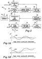
- the new satellite drift monitor or Z RAIM 92 of the present invention (which is claimed in the above referred to copending application) operates to determine if a drift has already begun when a signal from a new satellite is first acquired. This is explained with reference to Figures 3A and 3B.
- the RAIM discriminator Assuming that there are N satellites with good geometry, the RAIM discriminator, as known in the art for the nth satellite, is formed by the equation: Where b n / k is a well known satellite geometry dependent coefficient as seen in the above referred to publication, N is the number of satellites, k indicates the kth satellite and ⁇ pr k is the difference between the measured pseudo range (or smoothed pseudo range) and the predicted pseudo range for the kth satellite. Due to selective availability (SA, a deliberate noise signal superimposed on the output of the GPS by the DOD), the discriminator will vary as seen in Figure 3A.
- SA selective availability
- is the absolute value of the discriminator d n
- K md is the statistical sigma number corresponding to the missed detection probability P md
- ⁇ SA is the selective availability noise sigma
- is the absolute value of the satellite geometry dependent coefficient in equation (2) where the upper and lower indices are the same and equal to the satellite index, n.
- the discriminator will cross zero or reach a minimum value from time to time i.e. at least every 5 minutes.
- . and the estimated drift rate, r, at a 1-p md confidence level is r ⁇ min /t Where t is the time since the satellite was first received.
- HPL a required output in avionics equipment
- HPL n t hn SEL + K md rf ⁇ SA .
- K md the statistical sigma number corresponding to the missed detection probability P md
- rf is a reduction factor less than 1
- t hn t 2 n1 + t 2 n2
- t n1 and t n2 are elements of the least square solution matrix, T, that is well known in the art.
- the Acceleration Monitor 44 of the present invention should detect an acceleration. To achieve fail operation capability, a de-selection of a new satellite via paths 22, 23 and function 24 in figure 1 should be performed if the rate, r, exceeds a predetermined time dependent threshold. Only newly acquired satellites need to be monitored this way since satellites that are already used for positioning, are being monitored by the Acceleration Monitor 44.
Landscapes
- Engineering & Computer Science (AREA)
- Radar, Positioning & Navigation (AREA)
- Remote Sensing (AREA)
- Physics & Mathematics (AREA)
- General Physics & Mathematics (AREA)
- Automation & Control Theory (AREA)
- Computer Security & Cryptography (AREA)
- Computer Networks & Wireless Communication (AREA)
- Position Fixing By Use Of Radio Waves (AREA)
- Navigation (AREA)
- Gyroscopes (AREA)
Applications Claiming Priority (3)
| Application Number | Priority Date | Filing Date | Title |
|---|---|---|---|
| US09/118,046 US5969672A (en) | 1998-07-17 | 1998-07-17 | GPS signal fault isolation monitor |
| US118046 | 1998-07-17 | ||
| PCT/US1999/014282 WO2000004402A1 (en) | 1998-07-17 | 1999-06-25 | Gps signal fault isolation monitor |
Publications (2)
| Publication Number | Publication Date |
|---|---|
| EP1097391A1 EP1097391A1 (en) | 2001-05-09 |
| EP1097391B1 true EP1097391B1 (en) | 2002-11-27 |
Family
ID=22376208
Family Applications (1)
| Application Number | Title | Priority Date | Filing Date |
|---|---|---|---|
| EP99930650A Expired - Lifetime EP1097391B1 (en) | 1998-07-17 | 1999-06-25 | Gps signal fault isolation monitor |
Country Status (6)
| Country | Link |
|---|---|
| US (1) | US5969672A (https=) |
| EP (1) | EP1097391B1 (https=) |
| JP (1) | JP4446604B2 (https=) |
| CA (1) | CA2337876C (https=) |
| DE (1) | DE69904187T2 (https=) |
| WO (1) | WO2000004402A1 (https=) |
Families Citing this family (33)
| Publication number | Priority date | Publication date | Assignee | Title |
|---|---|---|---|---|
| US6353408B1 (en) * | 1998-03-31 | 2002-03-05 | U.S. Philips Corporation | Electronic navigation apparatus |
| US6924781B1 (en) * | 1998-09-11 | 2005-08-02 | Visible Tech-Knowledgy, Inc. | Smart electronic label employing electronic ink |
| DE19945121C2 (de) * | 1999-09-21 | 2001-12-13 | Mannesmann Vdo Ag | Verfahren zum Navigieren eines Fahrzeugs |
| JP4803862B2 (ja) * | 2000-03-30 | 2011-10-26 | 日本無線株式会社 | Gnss・慣性航法装置 |
| US6469660B1 (en) | 2000-04-13 | 2002-10-22 | United Parcel Service Inc | Method and system for displaying target icons correlated to target data integrity |
| US6466846B2 (en) | 2000-07-10 | 2002-10-15 | United Parcel Service Of America, Inc. | Method, apparatus, system, and computer software program product for determining position integrity in a system having a global navigation satellite system (GNSS) component |
| US6549829B1 (en) * | 2001-10-31 | 2003-04-15 | The Boeing Company | Skipping filter for inertially augmented landing system |
| AU2003287268A1 (en) * | 2002-10-29 | 2004-05-25 | Sirf Technology, Inc. | System and method for estimating clock acceleration and location determination |
| FR2852683B1 (fr) * | 2003-03-19 | 2005-05-20 | Airbus France | Procede et dispositif d'aide au pilotage d'un aeronef lors d'une approche de non precision pendant une phase d'atterrissage. |
| US6856905B2 (en) * | 2003-04-29 | 2005-02-15 | Garmin At, Inc. | Systems and methods for fault detection and exclusion in navigational systems |
| ATE505032T1 (de) | 2003-09-03 | 2011-04-15 | Visible Tech Knowledgy Inc | Elektronisch aktualisierbares label und display |
| US7102567B2 (en) * | 2003-10-29 | 2006-09-05 | Sirf Technology, Inc. | System and method for estimating clock acceleration and location determination |
| JP4736866B2 (ja) * | 2005-04-28 | 2011-07-27 | 株式会社デンソー | ナビゲーション装置 |
| US7501981B2 (en) * | 2005-11-18 | 2009-03-10 | Texas Instruments Incorporated | Methods and apparatus to detect and correct integrity failures in satellite positioning system receivers |
| DE102007006612B4 (de) * | 2007-02-06 | 2013-10-24 | Astrium Gmbh | Verfahren, Endgerät und Computerprogrammprodukt zum Erhöhen der Verfügbarkeit eines globalen Navigationssystems |
| EP1980867A3 (en) * | 2007-04-10 | 2009-11-25 | Qualcomm Incorporated | Multipath mitigation using sensors |
| US8359182B2 (en) * | 2007-04-25 | 2013-01-22 | Uti Limited Partnership | Methods and systems for evaluating the performance of MEMS-based inertial navigation systems |
| FR2916060B1 (fr) * | 2007-05-11 | 2009-07-10 | Airbus France Sa | Procede et dispositif de surveillance d'une position horizontale d'un avion roulant au sol. |
| US8457013B2 (en) | 2009-01-13 | 2013-06-04 | Metrologic Instruments, Inc. | Wireless dual-function network device dynamically switching and reconfiguring from a wireless network router state of operation into a wireless network coordinator state of operation in a wireless communication network |
| US8234507B2 (en) | 2009-01-13 | 2012-07-31 | Metrologic Instruments, Inc. | Electronic-ink display device employing a power switching mechanism automatically responsive to predefined states of device configuration |
| US9030356B2 (en) * | 2009-09-29 | 2015-05-12 | Texas Instruments Incorporated | Positioning system receiver sensor system coupled with measurement data output |
| FR2972810B1 (fr) * | 2011-03-16 | 2014-01-03 | Sagem Defense Securite | Detection et correction d'incoherence de phase porteuse en poursuite d'un signal de radionavigation |
| KR20140057662A (ko) | 2011-09-12 | 2014-05-13 | 콘티넨탈 테베스 아게 운트 코. 오하게 | 위성을 선택하기 위한 방법 |
| KR101877562B1 (ko) * | 2011-10-07 | 2018-08-10 | 한국전자통신연구원 | Gps 위성의 이상 상태 감시 장치 및 방법 |
| US9341718B2 (en) * | 2012-09-07 | 2016-05-17 | Honeywell International Inc. | Method and system for providing integrity for hybrid attitude and true heading |
| US9547086B2 (en) | 2013-03-26 | 2017-01-17 | Honeywell International Inc. | Selected aspects of advanced receiver autonomous integrity monitoring application to kalman filter based navigation filter |
| US9784844B2 (en) | 2013-11-27 | 2017-10-10 | Honeywell International Inc. | Architectures for high integrity multi-constellation solution separation |
| US10215862B2 (en) * | 2014-04-07 | 2019-02-26 | Honeywell International Inc. | Systems and methods for a code carrier divergence high-pass filter monitor |
| US9395384B1 (en) * | 2015-10-07 | 2016-07-19 | State Farm Mutual Automobile Insurance Company | Systems and methods for estimating vehicle speed and hence driving behavior using accelerometer data during periods of intermittent GPS |
| JP6750818B2 (ja) * | 2017-10-23 | 2020-09-02 | 国立研究開発法人宇宙航空研究開発機構 | 飛行体用航法装置および飛行体制御方法 |
| GB2600907A (en) * | 2020-08-10 | 2022-05-18 | Veeride Geo Ltd | Proximity-based navigation method |
| US12442936B2 (en) | 2021-06-14 | 2025-10-14 | Honeywell International Inc. | Inertial coasting position and velocity solution separation |
| CN115856952A (zh) * | 2022-12-05 | 2023-03-28 | 北京航空航天大学 | 一种复杂地形环境下araim可用性预测方法 |
Family Cites Families (7)
| Publication number | Priority date | Publication date | Assignee | Title |
|---|---|---|---|---|
| US5646843A (en) * | 1990-02-05 | 1997-07-08 | Caterpillar Inc. | Apparatus and method for surface based vehicle control system |
| US5606506A (en) * | 1993-04-05 | 1997-02-25 | Caterpillar Inc. | Method and apparatus for improving the accuracy of position estimates in a satellite based navigation system using velocity data from an inertial reference unit |
| US5787384A (en) * | 1995-11-22 | 1998-07-28 | E-Systems, Inc. | Apparatus and method for determining velocity of a platform |
| JP3338304B2 (ja) * | 1996-10-01 | 2002-10-28 | 横河電子機器株式会社 | 航法装置 |
| US5923286A (en) * | 1996-10-23 | 1999-07-13 | Honeywell Inc. | GPS/IRS global position determination method and apparatus with integrity loss provisions |
| JPH10132843A (ja) * | 1996-10-25 | 1998-05-22 | Murata Mfg Co Ltd | 速度演算装置 |
| US5757317A (en) * | 1997-03-17 | 1998-05-26 | Litton Systems, Inc. | Relative navigation utilizing inertial measurement units and a plurality of satellite transmitters |
-
1998
- 1998-07-17 US US09/118,046 patent/US5969672A/en not_active Expired - Lifetime
-
1999
- 1999-06-25 WO PCT/US1999/014282 patent/WO2000004402A1/en not_active Ceased
- 1999-06-25 CA CA002337876A patent/CA2337876C/en not_active Expired - Fee Related
- 1999-06-25 DE DE69904187T patent/DE69904187T2/de not_active Expired - Lifetime
- 1999-06-25 JP JP2000560468A patent/JP4446604B2/ja not_active Expired - Fee Related
- 1999-06-25 EP EP99930650A patent/EP1097391B1/en not_active Expired - Lifetime
Also Published As
| Publication number | Publication date |
|---|---|
| JP4446604B2 (ja) | 2010-04-07 |
| WO2000004402A1 (en) | 2000-01-27 |
| US5969672A (en) | 1999-10-19 |
| CA2337876A1 (en) | 2000-01-27 |
| CA2337876C (en) | 2005-09-20 |
| JP2002520625A (ja) | 2002-07-09 |
| EP1097391A1 (en) | 2001-05-09 |
| DE69904187T2 (de) | 2003-07-17 |
| DE69904187D1 (de) | 2003-01-09 |
Similar Documents
| Publication | Publication Date | Title |
|---|---|---|
| EP1097391B1 (en) | Gps signal fault isolation monitor | |
| EP1097390B1 (en) | Gps satellite drift monitor | |
| EP1456684B1 (en) | Fault detection and exclusion for gps systems | |
| US5760737A (en) | Navigation system with solution separation apparatus for detecting accuracy failures | |
| US6856905B2 (en) | Systems and methods for fault detection and exclusion in navigational systems | |
| US5631656A (en) | Fail safe system with common mode avoidance | |
| KR100203969B1 (ko) | 안정보장 감시 추정 항법장치 | |
| US5931889A (en) | Clock-aided satellite navigation receiver system for monitoring the integrity of satellite signals | |
| EP2113784B1 (en) | Systems and methods for determining location information using dual filters | |
| US7821454B2 (en) | Systems and methods for detecting GPS measurement errors | |
| JP2002520623A5 (https=) | ||
| US9983314B2 (en) | System for excluding a failure of a satellite in a GNSS system | |
| US20090182493A1 (en) | Navigation system with apparatus for detecting accuracy failures | |
| US20190377095A1 (en) | Signal fault detection for global navigation satellite system using multiple antennas | |
| WO2001020360A9 (en) | Solution separation method and apparatus for ground-augmented global positioning system | |
| CN114152958A (zh) | 一种基于多数据源的机载卫星导航欺骗式干扰检测方法 | |
| US6298316B1 (en) | Failure detection system | |
| EP3913403A1 (en) | Three-dimensional attitude determination system with multi-faceted integrity solution | |
| WO2004044608A1 (en) | Lock slip detection using inertial information | |
| US12111403B2 (en) | Error and integrity evaluation via motion prediction | |
| Kohli | GPS Integrity Monitoring Using an AHRS as Reference | |
| Ahlbrecht et al. | High Integrity Positioning: Lessons from the Aviation Industry |
Legal Events
| Date | Code | Title | Description |
|---|---|---|---|
| PUAI | Public reference made under article 153(3) epc to a published international application that has entered the european phase |
Free format text: ORIGINAL CODE: 0009012 |
|
| 17P | Request for examination filed |
Effective date: 20010116 |
|
| AK | Designated contracting states |
Kind code of ref document: A1 Designated state(s): DE FR GB |
|
| GRAG | Despatch of communication of intention to grant |
Free format text: ORIGINAL CODE: EPIDOS AGRA |
|
| GRAG | Despatch of communication of intention to grant |
Free format text: ORIGINAL CODE: EPIDOS AGRA |
|
| GRAH | Despatch of communication of intention to grant a patent |
Free format text: ORIGINAL CODE: EPIDOS IGRA |
|
| 17Q | First examination report despatched |
Effective date: 20020515 |
|
| GRAH | Despatch of communication of intention to grant a patent |
Free format text: ORIGINAL CODE: EPIDOS IGRA |
|
| GRAA | (expected) grant |
Free format text: ORIGINAL CODE: 0009210 |
|
| AK | Designated contracting states |
Kind code of ref document: B1 Designated state(s): DE FR GB |
|
| REG | Reference to a national code |
Ref country code: GB Ref legal event code: FG4D |
|
| REF | Corresponds to: |
Ref document number: 69904187 Country of ref document: DE Date of ref document: 20030109 |
|
| ET | Fr: translation filed | ||
| PLBE | No opposition filed within time limit |
Free format text: ORIGINAL CODE: 0009261 |
|
| STAA | Information on the status of an ep patent application or granted ep patent |
Free format text: STATUS: NO OPPOSITION FILED WITHIN TIME LIMIT |
|
| 26N | No opposition filed |
Effective date: 20030828 |
|
| REG | Reference to a national code |
Ref country code: FR Ref legal event code: PLFP Year of fee payment: 17 |
|
| PGFP | Annual fee paid to national office [announced via postgrant information from national office to epo] |
Ref country code: GB Payment date: 20150526 Year of fee payment: 17 |
|
| PGFP | Annual fee paid to national office [announced via postgrant information from national office to epo] |
Ref country code: FR Payment date: 20150528 Year of fee payment: 17 |
|
| PGFP | Annual fee paid to national office [announced via postgrant information from national office to epo] |
Ref country code: DE Payment date: 20150630 Year of fee payment: 17 |
|
| REG | Reference to a national code |
Ref country code: DE Ref legal event code: R119 Ref document number: 69904187 Country of ref document: DE |
|
| GBPC | Gb: european patent ceased through non-payment of renewal fee |
Effective date: 20160625 |
|
| REG | Reference to a national code |
Ref country code: FR Ref legal event code: ST Effective date: 20170228 |
|
| PG25 | Lapsed in a contracting state [announced via postgrant information from national office to epo] |
Ref country code: FR Free format text: LAPSE BECAUSE OF NON-PAYMENT OF DUE FEES Effective date: 20160630 Ref country code: DE Free format text: LAPSE BECAUSE OF NON-PAYMENT OF DUE FEES Effective date: 20170103 |
|
| PG25 | Lapsed in a contracting state [announced via postgrant information from national office to epo] |
Ref country code: GB Free format text: LAPSE BECAUSE OF NON-PAYMENT OF DUE FEES Effective date: 20160625 |
|
| P01 | Opt-out of the competence of the unified patent court (upc) registered |
Effective date: 20230525 |