EP1095849A2 - Vorrichtung zum Übertragen von Drehmomenten im Antriebsstrang von Wasserfahrzeugen, vorzugsweise mit Verbrennungsmotor - Google Patents
Vorrichtung zum Übertragen von Drehmomenten im Antriebsstrang von Wasserfahrzeugen, vorzugsweise mit Verbrennungsmotor Download PDFInfo
- Publication number
- EP1095849A2 EP1095849A2 EP00120193A EP00120193A EP1095849A2 EP 1095849 A2 EP1095849 A2 EP 1095849A2 EP 00120193 A EP00120193 A EP 00120193A EP 00120193 A EP00120193 A EP 00120193A EP 1095849 A2 EP1095849 A2 EP 1095849A2
- Authority
- EP
- European Patent Office
- Prior art keywords
- mass
- flywheel mass
- flywheel
- transmission
- ship
- Prior art date
- Legal status (The legal status is an assumption and is not a legal conclusion. Google has not performed a legal analysis and makes no representation as to the accuracy of the status listed.)
- Ceased
Links
- 230000005540 biological transmission Effects 0.000 title claims abstract description 18
- 238000002485 combustion reaction Methods 0.000 title claims description 3
- 230000008878 coupling Effects 0.000 claims abstract description 17
- 238000010168 coupling process Methods 0.000 claims abstract description 17
- 238000005859 coupling reaction Methods 0.000 claims abstract description 17
- 230000009977 dual effect Effects 0.000 claims description 2
- 230000010355 oscillation Effects 0.000 abstract 1
- 230000010360 secondary oscillation Effects 0.000 abstract 1
- 238000013016 damping Methods 0.000 description 5
- 238000010586 diagram Methods 0.000 description 2
- 230000000694 effects Effects 0.000 description 2
- 239000006096 absorbing agent Substances 0.000 description 1
- 230000006978 adaptation Effects 0.000 description 1
- 210000000078 claw Anatomy 0.000 description 1
- 230000006835 compression Effects 0.000 description 1
- 238000007906 compression Methods 0.000 description 1
- 230000001419 dependent effect Effects 0.000 description 1
- 210000003746 feather Anatomy 0.000 description 1
- 230000001360 synchronised effect Effects 0.000 description 1
Images

Classifications
-
- F—MECHANICAL ENGINEERING; LIGHTING; HEATING; WEAPONS; BLASTING
- F16—ENGINEERING ELEMENTS AND UNITS; GENERAL MEASURES FOR PRODUCING AND MAINTAINING EFFECTIVE FUNCTIONING OF MACHINES OR INSTALLATIONS; THERMAL INSULATION IN GENERAL
- F16F—SPRINGS; SHOCK-ABSORBERS; MEANS FOR DAMPING VIBRATION
- F16F15/00—Suppression of vibrations in systems; Means or arrangements for avoiding or reducing out-of-balance forces, e.g. due to motion
- F16F15/10—Suppression of vibrations in rotating systems by making use of members moving with the system
- F16F15/12—Suppression of vibrations in rotating systems by making use of members moving with the system using elastic members or friction-damping members, e.g. between a rotating shaft and a gyratory mass mounted thereon
- F16F15/131—Suppression of vibrations in rotating systems by making use of members moving with the system using elastic members or friction-damping members, e.g. between a rotating shaft and a gyratory mass mounted thereon the rotating system comprising two or more gyratory masses
- F16F15/133—Suppression of vibrations in rotating systems by making use of members moving with the system using elastic members or friction-damping members, e.g. between a rotating shaft and a gyratory mass mounted thereon the rotating system comprising two or more gyratory masses using springs as elastic members, e.g. metallic springs
- F16F15/134—Wound springs
- F16F15/13469—Combinations of dampers, e.g. with multiple plates, multiple spring sets, i.e. complex configurations
- F16F15/13476—Combinations of dampers, e.g. with multiple plates, multiple spring sets, i.e. complex configurations resulting in a staged spring characteristic, e.g. with multiple intermediate plates
-
- B—PERFORMING OPERATIONS; TRANSPORTING
- B63—SHIPS OR OTHER WATERBORNE VESSELS; RELATED EQUIPMENT
- B63H—MARINE PROPULSION OR STEERING
- B63H23/00—Transmitting power from propulsion power plant to propulsive elements
-
- B—PERFORMING OPERATIONS; TRANSPORTING
- B63—SHIPS OR OTHER WATERBORNE VESSELS; RELATED EQUIPMENT
- B63H—MARINE PROPULSION OR STEERING
- B63H23/00—Transmitting power from propulsion power plant to propulsive elements
- B63H23/32—Other parts
- B63H23/34—Propeller shafts; Paddle-wheel shafts; Attachment of propellers on shafts
-
- F—MECHANICAL ENGINEERING; LIGHTING; HEATING; WEAPONS; BLASTING
- F16—ENGINEERING ELEMENTS AND UNITS; GENERAL MEASURES FOR PRODUCING AND MAINTAINING EFFECTIVE FUNCTIONING OF MACHINES OR INSTALLATIONS; THERMAL INSULATION IN GENERAL
- F16F—SPRINGS; SHOCK-ABSORBERS; MEANS FOR DAMPING VIBRATION
- F16F15/00—Suppression of vibrations in systems; Means or arrangements for avoiding or reducing out-of-balance forces, e.g. due to motion
- F16F15/10—Suppression of vibrations in rotating systems by making use of members moving with the system
- F16F15/12—Suppression of vibrations in rotating systems by making use of members moving with the system using elastic members or friction-damping members, e.g. between a rotating shaft and a gyratory mass mounted thereon
- F16F15/131—Suppression of vibrations in rotating systems by making use of members moving with the system using elastic members or friction-damping members, e.g. between a rotating shaft and a gyratory mass mounted thereon the rotating system comprising two or more gyratory masses
- F16F15/13164—Suppression of vibrations in rotating systems by making use of members moving with the system using elastic members or friction-damping members, e.g. between a rotating shaft and a gyratory mass mounted thereon the rotating system comprising two or more gyratory masses characterised by the supporting arrangement of the damper unit
Definitions
- the device according to the invention for transmitting torques in the drive train of watercraft which are preferably driven by internal combustion engines, has a first flywheel arranged on the crankshaft and a second flywheel coupled to the shaft train of the ship's drive.
- the first and second flywheels are connected to one another in a torsionally elastic manner.
- the transmission behavior of the device according to the invention can be optimally adjusted for damping torsional vibrations via the parameters of the rigidity of the elastic connection, its damping and the coupled flywheel masses.
- the decisive step according to the invention is to arrange a second flywheel mass of high mass inertia on the driven side of the device and to allow a high angle of rotation between the first and second flywheel mass.
Landscapes
- Engineering & Computer Science (AREA)
- Mechanical Engineering (AREA)
- General Engineering & Computer Science (AREA)
- Chemical & Material Sciences (AREA)
- Combustion & Propulsion (AREA)
- Ocean & Marine Engineering (AREA)
- Physics & Mathematics (AREA)
- Acoustics & Sound (AREA)
- Aviation & Aerospace Engineering (AREA)
- Mechanical Operated Clutches (AREA)
- Shafts, Cranks, Connecting Bars, And Related Bearings (AREA)
Abstract
Description

Weiterhin ist es bereits vorbekannt, für die Wellenkupplung nach DE 43 09 745 A1 ein abtriebsseitig angeordnetes Kraftübertragungsglied mit erhöhtem Massenträgheitsmoment zu dimensionieren.
Neben einem hohen Antriebs- und Schaltkomfort kann durch niedrigeren Verschleiß und Verwenden von in der Automobilindustrie in Großserie eingeführten Bauteilen eine Kosteneinsparung erreicht werden.
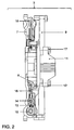
Das Zweimassenschwungrad 3 besteht aus einer fest mit der Kurbelwelle 2 des Motors 1 gekoppelten Primärschwungmasse 7 und einer mittels eines Kugellagers 12 drehbar auf deren Nabe 7 gelagerten Sekundärschwungmasse 9. Die Primärschwungmasse 7 trägt umfangsverteilt Federn 10, welche vorzugsweise als Druckfedern ausgebildet sind. In diese greifen, starr mit der Sekundärschwungmasse 9 verbundene, Koppelelemente 13 ein, welche damit unter Zwischenschalten der Federn 10 gegen die Primärschwungmasse 7 abgestützt sind.
Es erfolgt eine Kraftübertragung von der Kurbelwelle 2 zur Primärschwungmasse 7 und über die darin gehaltenen Federn 10 weiter zu den an der Sekundärschwungmasse 9 fest angeordneten Koppelelementen 13 und damit zur Sekundärschwungmasse 9. An dieser befindet sich ein auswechselbar angekoppelter Wellenadapter 11, über den die Kräfte weiter, auf die das Getriebe treibende Welle 4 übertragen werden. Über den Wellenadapter 11 ist die Anpassung der Verbindung zwischen Sekundärschwungmasse 9 und der Welle 4 des Getriebes 5 einfach gelöst.
Auf der Nabe 8 der Primärschwungmasse 7 ist mittels eines Kugellagers 12 die Sekundärschwungmasse 8 drehbar gelagert. Über Verbindungselemente 16 ist ein Koppelelement 13 fest mit der Sekundärschwungmasse 9 verbunden. Die Koppelelemente 13 greifen in die umfangsverteilten Federelemente 14 und 15, welche in der Primärschwungmasse 7 gehalten und radial gegen diese abgestützt sind. Ein Wellenadapter 11 ist zentrisch über Verbindungsemente 17 an der Sekundärschwungmasse 9 auswechselbar angeordnet. Er dient zum Ankoppeln der zum Getriebe 5 führenden Welle 4 - siehe Fig. 1 -.
- 1
- Schiffsmotor
- 2
- Kurbelwelle
- 3
- Zweimassenschwungrad
- 4
- Welle
- 5
- Getriebe
- 6
- Abtriebswelle
- 7
- Primärschwungmasse
- 8
- Nabe
- 9
- Sekundärschwungmasse
- 10
- Feder
- 11
- Wellenadapter
- 12
- Kugellager
- 13
- Koppelelement
- 14
- Federpackung
- 15
- Federpackung
- 16
- Verbindungselement
- 17
- Verbindungselement
- 18
- Fettpackung
Claims (5)
- Vorrichtung zum Übertragen von Drehmomenten im Antriebsstrang von Wasserfahrzeugen, vorzugsweise mit Verbrennungsmotoren, wobei zwischen der motorseitigen Primärschwungmasse und einem angekoppelten Abtrieb zu einem Getriebe, zum Antreiben eines Schiffspropellers, eine drehelastische Verbindung zwischengeschaltet ist
dadurch gekennzeichnet,
daß die drehelastische Verbindung auf der Seite ihres Abtriebes eine Sekundärschwungmasse (9) aufweist. - Vorrichtung nach Anspruch 1
dadurch gekennzeichnet,
daß die drehelastische Verbindung eine speziell für den Einsatz am Schiffsantrieb dimensionierte Sekundärschwungmasse eine, gegenüber den Antriebssträngen im Automobil, minimal um den Faktor 2 höhere Masse aufweist. - Vorrichtung nach Anspruch 1 o. 2
dadurch gekennzeichnet,
daß die Primärschwungmasse (7) des Motors (1), die drehelastische Verbindung und die Sekundärschwungmasse (9) durch ein an sich bekanntes Zweimassenschwungrad (3) gebildet wird. - Vorrichtung nach einem der vorherigen Ansprüche 1 o. 2
dadurch gekennzeichnet,
daß die drehelastische Verbindung zwischen der Primärschwungmasse (7) und der Sekundärschwungmasse (9) hohe Verdrehwinkel >30° zuläßt. - Vorrichtung nach Anspruch 1 o. 2
dadurch gekennzeichnet,
daß an der Sekundärschwungmasse (9) zentrisch ein auswechselbarer Wellenadapter (11) zum Ankoppeln einer Abtriebswelle (6) des Schiffsantriebs angeordnet ist.
Applications Claiming Priority (2)
| Application Number | Priority Date | Filing Date | Title |
|---|---|---|---|
| DE19952233A DE19952233B4 (de) | 1999-10-29 | 1999-10-29 | Vorrichtung zum Übertragen von Drehmomenten im Antriebsstrang von Wasserfahrzeugen, vorzugsweise mit Verbrennungsmotor |
| DE19952233 | 1999-10-29 |
Publications (2)
| Publication Number | Publication Date |
|---|---|
| EP1095849A2 true EP1095849A2 (de) | 2001-05-02 |
| EP1095849A3 EP1095849A3 (de) | 2003-06-04 |
Family
ID=7927373
Family Applications (1)
| Application Number | Title | Priority Date | Filing Date |
|---|---|---|---|
| EP00120193A Ceased EP1095849A3 (de) | 1999-10-29 | 2000-09-22 | Vorrichtung zum Übertragen von Drehmomenten im Antriebsstrang von Wasserfahrzeugen, vorzugsweise mit Verbrennungsmotor |
Country Status (3)
| Country | Link |
|---|---|
| US (1) | US6547612B1 (de) |
| EP (1) | EP1095849A3 (de) |
| DE (1) | DE19952233B4 (de) |
Families Citing this family (4)
| Publication number | Priority date | Publication date | Assignee | Title |
|---|---|---|---|---|
| JP5164731B2 (ja) * | 2008-08-08 | 2013-03-21 | 日本発條株式会社 | ダンパスプリング装置、フライホイール、クラッチディスク、ロックアップ機構用クラッチディスク |
| JP2012237258A (ja) * | 2011-05-12 | 2012-12-06 | Yamaha Motor Co Ltd | 船外機 |
| DE112015002307A5 (de) † | 2014-05-16 | 2017-02-09 | Schaeffler Technologies AG & Co. KG | Drehmomentübertragungsvorrichtung für Hybridfahrzeug |
| FR3036153B1 (fr) * | 2015-05-12 | 2017-06-09 | Messier Bugatti Dowty | Galet d'entrainement. |
Citations (2)
| Publication number | Priority date | Publication date | Assignee | Title |
|---|---|---|---|---|
| DE3915527A1 (de) | 1989-05-12 | 1990-11-15 | Hurth Masch Zahnrad Carl | Torsionsdaempfer fuer bootsgetriebe |
| DE4309745A1 (de) | 1993-03-26 | 1994-09-29 | Kirschey Centa Antriebe | Wellenkupplung |
Family Cites Families (10)
| Publication number | Priority date | Publication date | Assignee | Title |
|---|---|---|---|---|
| US1943517A (en) * | 1930-09-12 | 1934-01-16 | John F Daukus | Cushion flywheel |
| DE1096792B (de) * | 1958-11-05 | 1961-01-05 | Licentia Gmbh | Koerperschalldaempfung bei Schiffsantrieben, insbesondere bei Unterwasserfahrzeugen |
| DE3448510C2 (de) * | 1983-11-15 | 1996-12-05 | Luk Lamellen & Kupplungsbau | Vorrichtung zum Kompensieren von Drehstößen |
| JPH0612262Y2 (ja) * | 1985-08-20 | 1994-03-30 | アイシン精機株式会社 | トルク変動吸収装置 |
| JPH0792114B2 (ja) * | 1987-04-15 | 1995-10-09 | 株式会社大金製作所 | フライホイ−ル組立体 |
| JP2598799B2 (ja) * | 1987-11-30 | 1997-04-09 | 三信工業株式会社 | 船内外機用カップリング |
| US5065642A (en) * | 1989-02-28 | 1991-11-19 | Aisin Seiki Kabushiki Kaisha Kariya | Apparatus for absorbing torque variation |
| US5195396A (en) * | 1989-10-19 | 1993-03-23 | Aisin Seiki Kabushiki Kaisha | Torque variation absorbing device |
| EP0626523B1 (de) * | 1993-03-26 | 1996-12-11 | CENTA-ANTRIEBE KIRSCHEY GmbH | Zweistufige elastische Wellenkupplung |
| JPH10115347A (ja) * | 1996-10-11 | 1998-05-06 | Kawasaki Heavy Ind Ltd | 小型滑走艇の制振装置 |
-
1999
- 1999-10-29 DE DE19952233A patent/DE19952233B4/de not_active Expired - Fee Related
-
2000
- 2000-09-22 EP EP00120193A patent/EP1095849A3/de not_active Ceased
- 2000-10-27 US US09/698,731 patent/US6547612B1/en not_active Expired - Fee Related
Patent Citations (2)
| Publication number | Priority date | Publication date | Assignee | Title |
|---|---|---|---|---|
| DE3915527A1 (de) | 1989-05-12 | 1990-11-15 | Hurth Masch Zahnrad Carl | Torsionsdaempfer fuer bootsgetriebe |
| DE4309745A1 (de) | 1993-03-26 | 1994-09-29 | Kirschey Centa Antriebe | Wellenkupplung |
Also Published As
| Publication number | Publication date |
|---|---|
| EP1095849A3 (de) | 2003-06-04 |
| DE19952233A1 (de) | 2001-05-03 |
| DE19952233B4 (de) | 2009-02-26 |
| US6547612B1 (en) | 2003-04-15 |
Similar Documents
| Publication | Publication Date | Title |
|---|---|---|
| EP2753847B1 (de) | Fliehkraftpendel und kupplungsscheibe mit diesem | |
| DE102016204261B4 (de) | Zweimassenschwungrad mit Drehmomentbegrenzung und einem verdrehbaren Lagerflansch | |
| EP1304500A2 (de) | Antriebstrang mit einem Drehschwingungsdämpfer und einer drehelastischen Kupplung | |
| DE102018113585B4 (de) | Drehschwingungsdämpfer | |
| DE102013223753A1 (de) | Hydrodynamischer Drehmomentwandler | |
| DE3439701C2 (de) | ||
| DE102019118220A1 (de) | Antriebseinrichtung für einen hybridischen Antriebsstrang | |
| EP2923107A1 (de) | Wandlereinheit mit einem dämpfungssystem und mit einer drehmomentübertragungs-einheit | |
| DE19952233B4 (de) | Vorrichtung zum Übertragen von Drehmomenten im Antriebsstrang von Wasserfahrzeugen, vorzugsweise mit Verbrennungsmotor | |
| DE10319784A1 (de) | Integriertes Drehgeschwindigkeitsdämpfer-Bauteil für einen Antriebsstrang | |
| WO2012097988A1 (de) | Kraftfahrzeugantriebsstrang | |
| DE102012223950A1 (de) | Übertragungseinheit mit integriertem Dämpfersystem | |
| EP3156688B1 (de) | Torsionsschwingungsdämpfer für eine kurbelwelle | |
| DE102019107919A1 (de) | Hybrid-Dämpfer mit Drehmomentbegrenzer und Fliehkraftpendel | |
| DE102019118112A1 (de) | Wuchtaufspannung eines Zweimassenschwungrades mittels sekundärer Zusatzmasse | |
| DE19809425A1 (de) | Zweimassenschwungrad für eine Brennkraftmaschine | |
| EP1224410A1 (de) | Zweimassen-schwungrad | |
| DE102011104407B4 (de) | Schwingungsisolationsvorrichtung | |
| DE102017114445A1 (de) | Hydrodynamischer Drehmomentwandler mit Drehschwingungsdämpfer | |
| DE102020129741A1 (de) | Drehschwingungsdämpfer | |
| DE102020107702A1 (de) | Hybridantriebsstrang | |
| DE102012112462B4 (de) | Schwungrad mit einer Anordnung eines Torsionsschwingungsdämpfers | |
| DE102019130273A1 (de) | Drehmomentübertragungseinrichtung | |
| DE102019133130A1 (de) | Torsionsschwingungsdämpfer mit Hebelfedern und einer Rückhalteeinrichtung | |
| DE102022106742A1 (de) | Drehschwingungsdämpfer |
Legal Events
| Date | Code | Title | Description |
|---|---|---|---|
| PUAI | Public reference made under article 153(3) epc to a published international application that has entered the european phase |
Free format text: ORIGINAL CODE: 0009012 |
|
| AK | Designated contracting states |
Kind code of ref document: A2 Designated state(s): AT BE CH CY DE DK ES FI FR GB GR IE IT LI LU MC NL PT SE |
|
| AX | Request for extension of the european patent |
Free format text: AL;LT;LV;MK;RO;SI |
|
| PUAL | Search report despatched |
Free format text: ORIGINAL CODE: 0009013 |
|
| AK | Designated contracting states |
Designated state(s): AT BE CH CY DE DK ES FI FR GB GR IE IT LI LU MC NL PT SE |
|
| AX | Request for extension of the european patent |
Extension state: AL LT LV MK RO SI |
|
| RIC1 | Information provided on ipc code assigned before grant |
Ipc: 7B 63H 23/00 B Ipc: 7B 63H 23/34 B Ipc: 7F 16F 15/131 B Ipc: 7B 63H 23/30 A |
|
| 17P | Request for examination filed |
Effective date: 20031204 |
|
| AKX | Designation fees paid |
Designated state(s): AT BE CH CY DE DK ES FI FR GB GR IE IT LI LU MC NL PT SE |
|
| 17Q | First examination report despatched |
Effective date: 20040126 |
|
| APBN | Date of receipt of notice of appeal recorded |
Free format text: ORIGINAL CODE: EPIDOSNNOA2E |
|
| APBR | Date of receipt of statement of grounds of appeal recorded |
Free format text: ORIGINAL CODE: EPIDOSNNOA3E |
|
| APBV | Interlocutory revision of appeal recorded |
Free format text: ORIGINAL CODE: EPIDOSNIRAPE |
|
| APAF | Appeal reference modified |
Free format text: ORIGINAL CODE: EPIDOSCREFNE |
|
| APAF | Appeal reference modified |
Free format text: ORIGINAL CODE: EPIDOSCREFNE |
|
| APBT | Appeal procedure closed |
Free format text: ORIGINAL CODE: EPIDOSNNOA9E |
|
| STAA | Information on the status of an ep patent application or granted ep patent |
Free format text: STATUS: THE APPLICATION HAS BEEN REFUSED |
|
| 18R | Application refused |
Effective date: 20060206 |