EP1095737A2 - Disque support pour meule à lamelles - Google Patents
Disque support pour meule à lamelles Download PDFInfo
- Publication number
- EP1095737A2 EP1095737A2 EP00106457A EP00106457A EP1095737A2 EP 1095737 A2 EP1095737 A2 EP 1095737A2 EP 00106457 A EP00106457 A EP 00106457A EP 00106457 A EP00106457 A EP 00106457A EP 1095737 A2 EP1095737 A2 EP 1095737A2
- Authority
- EP
- European Patent Office
- Prior art keywords
- flange
- carrier plate
- flange back
- grinding
- support ring
- Prior art date
- Legal status (The legal status is an assumption and is not a legal conclusion. Google has not performed a legal analysis and makes no representation as to the accuracy of the status listed.)
- Granted
Links
Images

Classifications
-
- B—PERFORMING OPERATIONS; TRANSPORTING
- B24—GRINDING; POLISHING
- B24D—TOOLS FOR GRINDING, BUFFING OR SHARPENING
- B24D9/00—Wheels or drums supporting in exchangeable arrangement a layer of flexible abrasive material, e.g. sandpaper
- B24D9/08—Circular back-plates for carrying flexible material
-
- B—PERFORMING OPERATIONS; TRANSPORTING
- B24—GRINDING; POLISHING
- B24D—TOOLS FOR GRINDING, BUFFING OR SHARPENING
- B24D13/00—Wheels having flexibly-acting working parts, e.g. buffing wheels; Mountings therefor
- B24D13/14—Wheels having flexibly-acting working parts, e.g. buffing wheels; Mountings therefor acting by the front face
- B24D13/16—Wheels having flexibly-acting working parts, e.g. buffing wheels; Mountings therefor acting by the front face comprising pleated flaps or strips
Definitions
- the invention relates to a carrier plate for flap discs with a hub for the drive shaft and one Flange for the grinding flaps to be glued.
- the object of the invention is, by an appropriate design the carrier plate the use of press plates and to avoid the associated disadvantages.
- This configuration primarily achieves that the previously required press plates that exist between neighboring Lamellar grinding wheel had to be arranged, omitted.
- the adhesive flap on the Flange front are arranged in the usual way, support with its inner edge on the one hand and with one in the On the other hand, the ring surface lying near the outer edge region on the support rings.
- These support rings practice when Compress one of several to be produced Flap grinding discs existing block the necessary Pressure on these edge areas of the grinding flaps, the sufficient to hold the entire grinding flaps on both their Permanently define the surface as well as with each other.
- this embodiment of the invention also consists in the fact that the grinding flaps essentially only supported at their edge areas and with be applied to the pressure applied, so that the area remaining between the support rings Flange back is not burdened by the grinding flaps.
- This area is also used for falling abrasive grains not scratched during the pressing process or in any other way Way damaged. For this reason, can be more advantageous Way the flange back between the support rings as one be printable area designed for advertising purposes or user information can be used.
- the larger support ring in diameter is on formed outer edge of the flange back.
- the inner Support ring starting from a rising transition area from the flange back to the hub and the outer support ring through a bead on the outer edge of the flange back be educated. This creates the greatest pressure on the inside Border edge and in the outer edge area, which leads to a ring compound and partially overlapping each other Grinding flaps exercised. This means that when grinding particularly heavily loaded edge areas securely glued, whereby the stiffness of the individual grinding flaps the transmission sufficient pressure also in the interior this grinding flap ring ensures that sufficient Gluing takes place.
- the transition region can preferably be a fillet surface be trained. But it is also possible Design the transition area as a flat inclined surface.
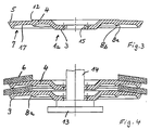
- the carrier plate 1 shown in section in the drawing for a lamellar grinding wheel 2 has a hub part 3 and one Flange 4 on.
- On the flange front 5 are grinding lamellae 6 arranged in a partially overlapping form, as is typical for this type of flap disc is.
- On the flange back 7 there are two support rings 8 and 9 trained on which the grinding flaps 6 are supported, the ring formed from the individual grinding lamellae with its inner edge facing away from the carrier plate 1 10 on the support ring 8 and with a further outside Area 11 is supported on the support ring 9.
- the support ring 8 is designed as a fillet surface, while the support ring 9 formed as a bead on the outer edge of the flange back 7 is.
- flap discs 2 are for adhesive operation under pressure on a stand 13 plugged with thru axle 14, the thru axle 14 a Has outer diameter that is only slightly smaller than the diameter of the receiving bore 15 of the carrier plate 1.
Landscapes
- Engineering & Computer Science (AREA)
- Mechanical Engineering (AREA)
- Polishing Bodies And Polishing Tools (AREA)
- Holding Or Fastening Of Disk On Rotational Shaft (AREA)
- Laminated Bodies (AREA)
Applications Claiming Priority (2)
| Application Number | Priority Date | Filing Date | Title |
|---|---|---|---|
| DE29914325U DE29914325U1 (de) | 1999-08-16 | 1999-08-16 | Trägerteller für Lamellenschleifscheiben |
| DE29914325U | 1999-08-16 |
Publications (3)
| Publication Number | Publication Date |
|---|---|
| EP1095737A2 true EP1095737A2 (fr) | 2001-05-02 |
| EP1095737A3 EP1095737A3 (fr) | 2003-06-04 |
| EP1095737B1 EP1095737B1 (fr) | 2004-11-24 |
Family
ID=8077586
Family Applications (1)
| Application Number | Title | Priority Date | Filing Date |
|---|---|---|---|
| EP00106457A Expired - Lifetime EP1095737B1 (fr) | 1999-08-16 | 2000-03-24 | Disque support pour meule à lamelles |
Country Status (4)
| Country | Link |
|---|---|
| EP (1) | EP1095737B1 (fr) |
| AT (1) | ATE283148T1 (fr) |
| DE (3) | DE29914325U1 (fr) |
| ES (1) | ES2157865T3 (fr) |
Cited By (2)
| Publication number | Priority date | Publication date | Assignee | Title |
|---|---|---|---|---|
| ITMI20101017A1 (it) * | 2010-06-08 | 2011-12-09 | C L M S Societa Cooperativa | Disco lamellare |
| CN102753308A (zh) * | 2010-02-18 | 2012-10-24 | 金世博股份公司 | 用于加工材料表面的转盘 |
Families Citing this family (1)
| Publication number | Priority date | Publication date | Assignee | Title |
|---|---|---|---|---|
| DE10106631A1 (de) | 2001-02-12 | 2002-08-22 | Rueggeberg August Gmbh & Co | Tragteller für Fächerschleifscheibe und Fächerschleifscheibe |
Citations (4)
| Publication number | Priority date | Publication date | Assignee | Title |
|---|---|---|---|---|
| DE9001995U1 (de) * | 1990-02-20 | 1990-04-26 | Lukas-Erzett Vereinigte Schleif- und Fräswerkzeugfabriken GmbH & Co KG, 5250 Engelskirchen | Schleiflamellenteller |
| DE9017256U1 (de) * | 1990-12-21 | 1991-03-14 | Wendt, Günther, 5227 Windeck | Fächerstirnschleifscheibe |
| EP0444272A1 (fr) * | 1990-03-01 | 1991-09-04 | Günther Wendt | Disque de polissage à éléments flexibles périfériques |
| DE29805508U1 (de) * | 1998-03-26 | 1998-05-20 | Lukas-Erzett Vereinigte Schleif- und Fräswerkzeugfabriken GmbH & Co KG, 51766 Engelskirchen | Werkzeug, insbesondere Schleif- oder Polierwerkzeug |
-
1999
- 1999-08-16 DE DE29914325U patent/DE29914325U1/de not_active Expired - Lifetime
-
2000
- 2000-03-24 EP EP00106457A patent/EP1095737B1/fr not_active Expired - Lifetime
- 2000-03-24 ES ES00106457T patent/ES2157865T3/es not_active Expired - Lifetime
- 2000-03-24 AT AT00106457T patent/ATE283148T1/de not_active IP Right Cessation
- 2000-03-24 DE DE20005548U patent/DE20005548U1/de not_active Expired - Lifetime
- 2000-03-24 DE DE50008733T patent/DE50008733D1/de not_active Expired - Fee Related
Patent Citations (4)
| Publication number | Priority date | Publication date | Assignee | Title |
|---|---|---|---|---|
| DE9001995U1 (de) * | 1990-02-20 | 1990-04-26 | Lukas-Erzett Vereinigte Schleif- und Fräswerkzeugfabriken GmbH & Co KG, 5250 Engelskirchen | Schleiflamellenteller |
| EP0444272A1 (fr) * | 1990-03-01 | 1991-09-04 | Günther Wendt | Disque de polissage à éléments flexibles périfériques |
| DE9017256U1 (de) * | 1990-12-21 | 1991-03-14 | Wendt, Günther, 5227 Windeck | Fächerstirnschleifscheibe |
| DE29805508U1 (de) * | 1998-03-26 | 1998-05-20 | Lukas-Erzett Vereinigte Schleif- und Fräswerkzeugfabriken GmbH & Co KG, 51766 Engelskirchen | Werkzeug, insbesondere Schleif- oder Polierwerkzeug |
Cited By (3)
| Publication number | Priority date | Publication date | Assignee | Title |
|---|---|---|---|---|
| CN102753308A (zh) * | 2010-02-18 | 2012-10-24 | 金世博股份公司 | 用于加工材料表面的转盘 |
| ITMI20101017A1 (it) * | 2010-06-08 | 2011-12-09 | C L M S Societa Cooperativa | Disco lamellare |
| EP2394789A1 (fr) * | 2010-06-08 | 2011-12-14 | C.L.M.S. Società Cooperativa | Disque à lamelles |
Also Published As
| Publication number | Publication date |
|---|---|
| EP1095737B1 (fr) | 2004-11-24 |
| ATE283148T1 (de) | 2004-12-15 |
| DE29914325U1 (de) | 1999-12-23 |
| ES2157865T1 (es) | 2001-09-01 |
| DE50008733D1 (de) | 2004-12-30 |
| DE20005548U1 (de) | 2000-08-10 |
| ES2157865T3 (es) | 2005-05-16 |
| EP1095737A3 (fr) | 2003-06-04 |
Similar Documents
| Publication | Publication Date | Title |
|---|---|---|
| DE69700301T2 (de) | Gerät und Verfahren zum Kleben von Plattenhälften zur Herstellung von optischen Datenspeicherplatten | |
| DE3541347C1 (de) | Faecherstirnschleifscheibe | |
| DE69729522T2 (de) | Plattenantriebsvorrichtung | |
| EP2265410B1 (fr) | Meule de dégrossissage | |
| DE2524803C3 (de) | Bremsscheibe | |
| EP1095737B1 (fr) | Disque support pour meule à lamelles | |
| DE3545842A1 (de) | Mit druckmittel-hilfskraft betaetigbare lamellenkupplung mit einer mitnahmezaehne zu ihrer drehsicherung aufweisenden tellerfelder | |
| EP0270556B1 (fr) | Dispositif comportant un mandrin et une meule, en particulier pour les dentistes ainsi que procede pour sa fabrication | |
| DE4414058A1 (de) | Kupplungsscheibe o. dgl. und Verfahren zu ihrer Herstellung | |
| DE102011100792A1 (de) | Flexible Schleifscheibe | |
| DE69713968T2 (de) | Fächerschleifscheibe | |
| DE19880564B4 (de) | Reibbeläge tragende Scheibe für eine mechanische Kupplung | |
| DE4432168A1 (de) | Lamellenschleifscheibe | |
| DE102006043989A1 (de) | Lamellenschleifscheibe | |
| DE102015011442A1 (de) | Fächerschleifscheibe, Tragteller dafür und Verfahren zu deren Herstellung | |
| DE2403112C3 (de) | Bremssegment mit einem Graphit-Reibelement für Hochleistungs-Mehrscheibenbremsen | |
| DE3230024A1 (de) | Kupplungsscheibe | |
| DE2306558C3 (de) | Schleif- oder Polierkopf | |
| DE9216621U1 (de) | Schleifwerkzeug | |
| EP1896273A1 (fr) | Dispositif de freinage d'un vehicule sur rails | |
| DE534073C (de) | Vorrichtung zum Abrichten der zylindrischen Flaeche von Schleifscheiben | |
| DE2500626A1 (de) | Topffoermige schleif- oder polierscheibe | |
| DE433395C (de) | Scheibenrad | |
| DE2645875C3 (de) | Fahrzeugrad mit einer Flachbettfelge verhältnismäßig kleinen AuBendurchmessers | |
| DE623057C (de) | Fahrzeugbremse |
Legal Events
| Date | Code | Title | Description |
|---|---|---|---|
| PUAI | Public reference made under article 153(3) epc to a published international application that has entered the european phase |
Free format text: ORIGINAL CODE: 0009012 |
|
| AK | Designated contracting states |
Kind code of ref document: A2 Designated state(s): AT BE CH CY DE DK ES FI FR GB GR IE IT LI LU MC NL PT SE |
|
| AX | Request for extension of the european patent |
Free format text: AL;LT;LV;MK;RO;SI |
|
| REG | Reference to a national code |
Ref country code: ES Ref legal event code: BA2A Ref document number: 2157865 Country of ref document: ES Kind code of ref document: T1 |
|
| PUAL | Search report despatched |
Free format text: ORIGINAL CODE: 0009013 |
|
| AK | Designated contracting states |
Designated state(s): AT BE CH CY DE DK ES FI FR GB GR IE IT LI LU MC NL PT SE |
|
| AX | Request for extension of the european patent |
Extension state: AL LT LV MK RO SI |
|
| RIC1 | Information provided on ipc code assigned before grant |
Ipc: 7B 24D 13/16 B Ipc: 7B 24D 9/08 A Ipc: 7B 24D 18/00 B |
|
| 17P | Request for examination filed |
Effective date: 20031020 |
|
| AKX | Designation fees paid |
Designated state(s): AT DE ES IT |
|
| GRAP | Despatch of communication of intention to grant a patent |
Free format text: ORIGINAL CODE: EPIDOSNIGR1 |
|
| GRAS | Grant fee paid |
Free format text: ORIGINAL CODE: EPIDOSNIGR3 |
|
| GRAA | (expected) grant |
Free format text: ORIGINAL CODE: 0009210 |
|
| AK | Designated contracting states |
Kind code of ref document: B1 Designated state(s): AT DE ES IT |
|
| REF | Corresponds to: |
Ref document number: 50008733 Country of ref document: DE Date of ref document: 20041230 Kind code of ref document: P |
|
| REG | Reference to a national code |
Ref country code: IE Ref legal event code: FG4D Free format text: GERMAN |
|
| REG | Reference to a national code |
Ref country code: ES Ref legal event code: FG2A Ref document number: 2157865 Country of ref document: ES Kind code of ref document: T3 |
|
| REG | Reference to a national code |
Ref country code: IE Ref legal event code: FD4D |
|
| PLBE | No opposition filed within time limit |
Free format text: ORIGINAL CODE: 0009261 |
|
| STAA | Information on the status of an ep patent application or granted ep patent |
Free format text: STATUS: NO OPPOSITION FILED WITHIN TIME LIMIT |
|
| 26N | No opposition filed |
Effective date: 20050825 |
|
| PGFP | Annual fee paid to national office [announced via postgrant information from national office to epo] |
Ref country code: AT Payment date: 20070313 Year of fee payment: 8 |
|
| PGFP | Annual fee paid to national office [announced via postgrant information from national office to epo] |
Ref country code: ES Payment date: 20070329 Year of fee payment: 8 |
|
| PGFP | Annual fee paid to national office [announced via postgrant information from national office to epo] |
Ref country code: DE Payment date: 20070529 Year of fee payment: 8 |
|
| PGFP | Annual fee paid to national office [announced via postgrant information from national office to epo] |
Ref country code: IT Payment date: 20070615 Year of fee payment: 8 |
|
| PG25 | Lapsed in a contracting state [announced via postgrant information from national office to epo] |
Ref country code: AT Free format text: LAPSE BECAUSE OF NON-PAYMENT OF DUE FEES Effective date: 20080324 |
|
| PG25 | Lapsed in a contracting state [announced via postgrant information from national office to epo] |
Ref country code: DE Free format text: LAPSE BECAUSE OF NON-PAYMENT OF DUE FEES Effective date: 20081001 |
|
| REG | Reference to a national code |
Ref country code: ES Ref legal event code: FD2A Effective date: 20080325 |
|
| PG25 | Lapsed in a contracting state [announced via postgrant information from national office to epo] |
Ref country code: ES Free format text: LAPSE BECAUSE OF NON-PAYMENT OF DUE FEES Effective date: 20080325 |
|
| PG25 | Lapsed in a contracting state [announced via postgrant information from national office to epo] |
Ref country code: IT Free format text: LAPSE BECAUSE OF NON-PAYMENT OF DUE FEES Effective date: 20080324 |