EP1094879B1 - Dieselabgasfilter - Google Patents
Dieselabgasfilter Download PDFInfo
- Publication number
- EP1094879B1 EP1094879B1 EP99932676A EP99932676A EP1094879B1 EP 1094879 B1 EP1094879 B1 EP 1094879B1 EP 99932676 A EP99932676 A EP 99932676A EP 99932676 A EP99932676 A EP 99932676A EP 1094879 B1 EP1094879 B1 EP 1094879B1
- Authority
- EP
- European Patent Office
- Prior art keywords
- filter
- filter body
- particles
- soot
- coating
- Prior art date
- Legal status (The legal status is an assumption and is not a legal conclusion. Google has not performed a legal analysis and makes no representation as to the accuracy of the status listed.)
- Expired - Lifetime
Links
Images
Classifications
-
- F—MECHANICAL ENGINEERING; LIGHTING; HEATING; WEAPONS; BLASTING
- F01—MACHINES OR ENGINES IN GENERAL; ENGINE PLANTS IN GENERAL; STEAM ENGINES
- F01N—GAS-FLOW SILENCERS OR EXHAUST APPARATUS FOR MACHINES OR ENGINES IN GENERAL; GAS-FLOW SILENCERS OR EXHAUST APPARATUS FOR INTERNAL COMBUSTION ENGINES
- F01N3/00—Exhaust or silencing apparatus having means for purifying, rendering innocuous, or otherwise treating exhaust
- F01N3/02—Exhaust or silencing apparatus having means for purifying, rendering innocuous, or otherwise treating exhaust for cooling, or for removing solid constituents of, exhaust
-
- B—PERFORMING OPERATIONS; TRANSPORTING
- B01—PHYSICAL OR CHEMICAL PROCESSES OR APPARATUS IN GENERAL
- B01D—SEPARATION
- B01D39/00—Filtering material for liquid or gaseous fluids
- B01D39/14—Other self-supporting filtering material ; Other filtering material
- B01D39/20—Other self-supporting filtering material ; Other filtering material of inorganic material, e.g. asbestos paper, metallic filtering material of non-woven wires
- B01D39/2068—Other inorganic materials, e.g. ceramics
- B01D39/2093—Ceramic foam
-
- F—MECHANICAL ENGINEERING; LIGHTING; HEATING; WEAPONS; BLASTING
- F01—MACHINES OR ENGINES IN GENERAL; ENGINE PLANTS IN GENERAL; STEAM ENGINES
- F01N—GAS-FLOW SILENCERS OR EXHAUST APPARATUS FOR MACHINES OR ENGINES IN GENERAL; GAS-FLOW SILENCERS OR EXHAUST APPARATUS FOR INTERNAL COMBUSTION ENGINES
- F01N3/00—Exhaust or silencing apparatus having means for purifying, rendering innocuous, or otherwise treating exhaust
- F01N3/02—Exhaust or silencing apparatus having means for purifying, rendering innocuous, or otherwise treating exhaust for cooling, or for removing solid constituents of, exhaust
- F01N3/021—Exhaust or silencing apparatus having means for purifying, rendering innocuous, or otherwise treating exhaust for cooling, or for removing solid constituents of, exhaust by means of filters
- F01N3/022—Exhaust or silencing apparatus having means for purifying, rendering innocuous, or otherwise treating exhaust for cooling, or for removing solid constituents of, exhaust by means of filters characterised by specially adapted filtering structure, e.g. honeycomb, mesh or fibrous
-
- F—MECHANICAL ENGINEERING; LIGHTING; HEATING; WEAPONS; BLASTING
- F01—MACHINES OR ENGINES IN GENERAL; ENGINE PLANTS IN GENERAL; STEAM ENGINES
- F01N—GAS-FLOW SILENCERS OR EXHAUST APPARATUS FOR MACHINES OR ENGINES IN GENERAL; GAS-FLOW SILENCERS OR EXHAUST APPARATUS FOR INTERNAL COMBUSTION ENGINES
- F01N3/00—Exhaust or silencing apparatus having means for purifying, rendering innocuous, or otherwise treating exhaust
- F01N3/02—Exhaust or silencing apparatus having means for purifying, rendering innocuous, or otherwise treating exhaust for cooling, or for removing solid constituents of, exhaust
- F01N3/021—Exhaust or silencing apparatus having means for purifying, rendering innocuous, or otherwise treating exhaust for cooling, or for removing solid constituents of, exhaust by means of filters
- F01N3/023—Exhaust or silencing apparatus having means for purifying, rendering innocuous, or otherwise treating exhaust for cooling, or for removing solid constituents of, exhaust by means of filters using means for regenerating the filters, e.g. by burning trapped particles
-
- F—MECHANICAL ENGINEERING; LIGHTING; HEATING; WEAPONS; BLASTING
- F01—MACHINES OR ENGINES IN GENERAL; ENGINE PLANTS IN GENERAL; STEAM ENGINES
- F01N—GAS-FLOW SILENCERS OR EXHAUST APPARATUS FOR MACHINES OR ENGINES IN GENERAL; GAS-FLOW SILENCERS OR EXHAUST APPARATUS FOR INTERNAL COMBUSTION ENGINES
- F01N2250/00—Combinations of different methods of purification
- F01N2250/02—Combinations of different methods of purification filtering and catalytic conversion
-
- F—MECHANICAL ENGINEERING; LIGHTING; HEATING; WEAPONS; BLASTING
- F01—MACHINES OR ENGINES IN GENERAL; ENGINE PLANTS IN GENERAL; STEAM ENGINES
- F01N—GAS-FLOW SILENCERS OR EXHAUST APPARATUS FOR MACHINES OR ENGINES IN GENERAL; GAS-FLOW SILENCERS OR EXHAUST APPARATUS FOR INTERNAL COMBUSTION ENGINES
- F01N2330/00—Structure of catalyst support or particle filter
- F01N2330/06—Ceramic, e.g. monoliths
-
- F—MECHANICAL ENGINEERING; LIGHTING; HEATING; WEAPONS; BLASTING
- F01—MACHINES OR ENGINES IN GENERAL; ENGINE PLANTS IN GENERAL; STEAM ENGINES
- F01N—GAS-FLOW SILENCERS OR EXHAUST APPARATUS FOR MACHINES OR ENGINES IN GENERAL; GAS-FLOW SILENCERS OR EXHAUST APPARATUS FOR INTERNAL COMBUSTION ENGINES
- F01N2330/00—Structure of catalyst support or particle filter
- F01N2330/10—Fibrous material, e.g. mineral or metallic wool
Definitions
- the present invention concerns improved filters for flue gas filtration.
- WFF Wall Flow Filters
- Soot filters are also manufactured as a relatively thick-walled pipe structure, from pressed metal wire, by Johnson Matthey Ltd., or ceramic wire mesh or, from foam ceramic structures manufactured by Alusuisse AG. Most of the known methods result in relatively low soot filtration efficiencies and significant soot blow-off, further reducing the filtration efficiency.
- Accumulated particulate matter from a diesel engine will react with oxygen when exposed to temperatures higher than 550°C in air with 21 per cent of oxygen. With decreasing oxygen concentrations, higher temperatures are required.
- Regeneration of flue gas filters is often accomplished by a few rather complicated techniques typically employing external heat supplies and where the whole filter structure, including the particulate matter, is heated with external energy from an oil burner or an electrical heating apparatus.
- Precious metals such as platinum and palladium are known to oxidize organic gases and organic matter at relatively low temperatures; carbon monoxide may be oxidized at temperatures as low as 200°C in situations where the carbon monoxide interacts with a large surface area of the precious metal.
- Diesel soot filter regeneration temperatures not lower than 400°C have been reached on Coming EX-47 or EX-66 Wall Flow Filters, using either a platinum or a vanadium pentoxide coating.
- active coatings known per se are supplied to the actual surface of the body and do not penetrate deeply into the porous structure thereof.
- Degussa AG has tested several coatings and have undertaken field trials showing that a vanadium pentoxide coating can reduce the regeneration temperature by a reasonable margin.
- regeneration temperatures in the order of 350°C have been achieved when applying a surface-increasing coating and a catalytically active substance on a large surface metal wire mesh filter body. This is described by M. F. Buchman and B. E. Enga from Johnson Matthey, Inc. in SAE (Society of Automotive Engineering) paper number 840080 with the title : "Regeneration Behavior af Light-Duty Catalytic Trap Oxidizer Systems".
- This coating may be in the form of a so-called wash coat which is deposited by "washing" a solution or slurry containing the catalytically active substance through the filter body in order for some of the substance to deposit on the filter wall.
- wash coat a so-called wash coat which is deposited by "washing" a solution or slurry containing the catalytically active substance through the filter body in order for some of the substance to deposit on the filter wall.
- the thickness of the coating will in general be so large that a porous material having a pore size of 15-25 ⁇ m would have a significantly reduced pore size after the deposition of these two coatings. Thus, it is not recommendable to use this technique on filters having an initial pore size lower than e.g. 25 ⁇ m.
- the catalytic conversion of hazardous exhaust gases is strongly dependent upon the contact time.
- the contact time will be increased when the contact area is increased, thus giving a higher conversion rate.
- the catalytic activity of an applied catalyst towards particulate matter is also strongly dependent on the contact area.
- a larger contact area will reduce the overalt layer thickness of the deposited soot, and the time required for complete regeneration - soot bum off - will thus be reduced.
- a reduced layer thickness of the soot will increase the rate of regeneration at low temperatures since the soot bums when in contact with the catalyst on and inside the filter wall.
- EP 0736503 upon which the pre-characterising portion of claim 1 is based, discloses an Exhaust gas purifying filter and a process for its production.
- the disclosed filter is a usual honeycomb-filter with a plurality of plugged channels.
- the porous matrix of the filter is formed by sintering ceramic powder, i.e. ceramic particles, which are thus bonded together.
- the document further discloses a catalytically active material coated on the surfaces within the porous matrix and additional coating, which act as membranes having pore sizes of about 10 microns. Due to the porous structure of the disclosed filter, soot particles are not allowed to penetrate into the interior of the wall structure and therefore the disclosed filter provides a relatively small contact area and therefore a relatively low catalytic activity.
- US 4,846,906 discloses a porous ceramic filtering element with a membrane arranged to be integral with the body portion of the element at an outlet surface thereof.
- the filter does not have a catalytic active layer and is provided with a large wall thickness compared with the wall thickness of a usual honeycomb filter.
- the preferred method of regenerating a filter on a vehicle is to have the regeneration take place at relatively low temperatures, which will eliminate the need for expensive and sophisticated external hardware to heat up the filter and control the process. This is furthermore advantageous with respect to safety of the vehicles. It is not preferred to have a hot piece of ceramics of metal in the remains of e.g. a crashed car where fuel may be leaking from the tank. In addition, it is not preferred to have a very hot filter enclosure positioned under a car driving or parking in e.g. long grass, as this grass may be ignited by the filter enclosure. Thus, the lower the temperature of the filter body, the safer the vehicle altogether.
- Mizrah, T., Gabathuler, J.-P., Gauckler, L, Baiker, A., Padeste, L & Meyer, H.P compared the soot ignition temperature for ceramic foam filters and Wall Flow Filters.
- the ceramic foam filter is a depth filter with rather low trapping efficiency (58 to 67%) compared to approximately 90% for the WFF.
- the catalytic coatings tested were Degussa D313 and D345 on Coming WFF. No surface-increasing coating was applied.
- soot may be deposited in a depth of up to in the order of from minus 200 ⁇ m (on top of the filter) to plus 1000 ⁇ m (inside the filtering wall).
- the soot particles are allowed to travel into the interior of the filter, such as into the interior of the filtering wall of the WFF, where they are removed by decomposition by contact with a suitable catalyst which has been deposited in the interior of the filter.
- the volume actually holding the soot is thus dramatically increased, as also at least parts of the inner surface of the filter body hold the soot.
- the catalytically active substance is deposited not only on the outer surface of the filtering wall, but also on the internal surface of the filter body wall, whereby the active area of the surface on which the catalytically active substance and the trapped soot interact is increased, resulting in a decreased regeneration temperature of the soot on the filter body when the catalytically active coating is an oxidizing coating.
- the inner surface of the filter body is defined by the walls of the paths used by the gas to travel through the filter body.
- this inner surface is constituted by the surfaces of the particles constituting the filter body.
- the inner surface of the filter body may be further increased by depositing a surface-increasing coating, such as a so-called wash-coat, on the surface, including the inner surface, of the filter body prior to the deposition of the catalytically active substance.
- a surface-increasing coating such as a so-called wash-coat
- the regeneration temperature of the filter body may, in suitable embodiments of the invention, be reduced to a temperature as low as 350°C or even 330°C or lower.
- even a further increase in the surface of the filter body may be obtained by providing a filter body having a relatively larger mean pore size, such as 30-200 ⁇ m, that allows the soot particles to penetrate deeper into the wall structure and, thus, interact with the active coating on an even larger surface.
- the invention constitutes a considerable improvement compared to known Wall Flow Filters, which are known to build up a soot particle filter cake on the surface only, with very little soot penetration into the structure, resulting in a requirement for regeneration temperatures of at least 400°C.
- soot ignition temperature may be lowered considerably with Cu- or Fe-based additives (of types known per se) supplied to and soluble in the diesel fuel as an organometallic fluid.
- a membrane is supplied to the filter wall outlet side.
- This membrane has a considerably lower pore size than the filter body wall, ensuring a very high filtration efficiency, also when the filter is clean with no filter cake.
- Known Wall Flow Filters depend strongly on the filter cake to increase the trapping efficiency from 70-80% with a clean filter to 85-90% with a filter cake partly covering the filtering wall.
- the provision of a membrane on the filter wall outlet side makes it possible to choose the pore size of the porous sintered filter body so large that part of the soot is not filtered by the filter body but would actually blow through the filter body if the membrane having a smaller pore size were not deposited on the outer surface of the filter body.
- a membrane having a pore size smaller than that of the filter body has been deposited on the filter body of known filters for increasing the filtering efficiency of the filter body.
- this membrane is required when filtering very small particles, such as dust particles.
- the membranes are positioned on the gas entrance side of the filtering walls of the filter body. The membrane prevents penetration of the dust into the filter body, as dust particles are not readily removed from the inside of a filter body. It will be appreciated that this arrangement is basically different from the arrangement according to the present invention where the membrane is not used to prevent soot particles from penetrating into the filter body, but is rather used to prevent the soot particles (which are allowed to penetrate into the filter body) from leaving the filter body.
- a membrane is preferably positioned on the gas outlet side of the filtering wall of the filter body, as penetration of the soot into the filter body is highly desired; this increases the area of the active surface of the filter.
- the area in which the soot and the catalytically active substance are in contact will be substantially the whole of the inner surface of the filter body in addition to the outer surface of the gas entrance side of the filtering wall of the filter body.
- the membrane solely serves the purpose of allowing a large active contact area and on the same time assuring a suitable, high filtering efficiency of the filter body.
- the membrane by means of a gradient of the pore size of the filter body along the thickness of the filter wall, starting with relatively large particles resulting in relative large pores such as, e.g., pores of a size of 35-500 ⁇ m and ending with pores which are sufficiently small to ensure that the soot will not leave the filter on the outlet side, such as, e.g., a pore size of 5-10 ⁇ m in an intermediary layer and down to a pore size of 0.5-5 ⁇ m, such as 1-2 ⁇ m, in an outermost layer on the outlet side. It is also possible to have a transition directly from a particle size giving large pores to a particle size giving sufficiently small pores to act as the soot-particle-stopping membrane.
- Wall Flow Filters made by powder technology can act as a combined surface and depth filters, that is, where part of the particles are allowed to penetrate into the filtering wall, and a membrane on the outlet side of the filter wall, a constant high filtration efficiency is achieved in combination with high contact area between the soot and the catalytically active coating inside the filter's porous internal wall structure.
- the present invention is also believed to be very important and advantageous in connection with removal of the very small soot particles generated by modern highly efficient diesel engines.
- These modem diesel engines generate soot particles which are considerably smaller than the soot particles generated by the previous, generations of diesel engines (these previous generations are however, still in use all over the world and will be in use for many years to come).
- modem diesel engines typically generate particles of sizes in the range of 50 nanometers to 1 ⁇ m, in particular in the range of 50 nanometers to 500 nanometers, and an important aspect of the invention relates to the removal of soot particles in this size range using the fitter principle according to the invention.
- Ceramic filters are often preferred when the process environment contains hot gases with a relatively low oxygen content and the possibility of a relatively high sulphur content.
- Silicon carbide has a number of advantages over other materials used in filters, such as oxide ceramics, metals, organic fibres and other ceramics.
- SiC is long time stable in an oxidising atmosphere up to temperatures as high as 1500°C.
- Pure, solid SiC has a high physical strength, even at high temperatures.
- the strength of solid SiC is 7 times the strength of solid alumina at 1.000°C.
- the base material of the powder technology honeycomb filter body is preferably ceramic particles, and will normally have an average mean particle size in the range of 1-250 ⁇ m, such as in the range of 10-150 ⁇ m, preferably in the range of 30-100 ⁇ m, giving filters with pore sizes ranging from 10-200 ⁇ m, preferably 20-100 ⁇ m, such as 40-80 ⁇ m.
- SiC silicon carbide elements
- 12 commercial grades of SiC are presently the preferred starting products for producing the porous silicon carbide elements, such as Mesh 40, 60, 80, 120, 150, 180, 220, 280, 320, 360, 400, 600 (according to FEPA standards (FEPA: Federation of the European Producers of Abrasives)).
- Production methods normally employ continuous barrel/auger extrusion, but also other commonly known ceramic shaping processes, such as tape-casting, iso-static casting, slip-casting and other casting methods may be used.
- the presently preferred manufacturing method of the filter bodies is extrusion and sintering of a paste comprising particles of a ceramic and/or metallic material, a permanent binder, one or more green binders and a liquid.
- the outer surface of the particles melt slightly, whereby, after cooling of the sintered body, the sintered body is solidified by the melted metal which solidifies also in menisci in the boundaries between the particles.
- the holes between the interconnected particles may form the actual pores of the filter body.
- the choice of particle size defines the pore size of the sintered material.
- the pores of the sintered material will have a narrow distribution, as identical size/shape particles define identical pores.
- a permanent binder is preferably incorporated in the paste to be shaped and sintered to form the porous filter body. During sintering, this permanent binder will interconnect the SiC particles and, thus, solidify the filter body in the desired shape and in a manner so that the SiC particles, as described above, directly define the pores of the material.
- the permanent binder is constituted by small particles of SiC, such as microfine eller ultrafine SiC, e.g. microcrystalline SiC, having a particle size in the interval 0.1-10 ⁇ m.
- This microfine SiC will, due to the evaporation pressure of particles having a small radius of curvature being larger than that of particles having a larger radius of curvature, evaporate or decompose at a temperature where the larger particles are more stable, and solidify among other places in the boundaries of the large SiC particles in the filter body.
- the sintered filter body consists of SiC particles, again defining the porosity of the filter body, interconnected by SiC.
- This all-SiC filter body is highly preferred, as SiC has superior properties in flue gas filters, and as no other materials having less optimum properties are present in the filter body to reduce the overall properties of the filter body.
- Extrusion of a microfine or sub-micron or micro-crystalline powder-based material to a honeycomb monolith or pipes using a pore-forming agent to form the porosity of the filter body is an alternative method for producing structures with a controlled pore size.
- the pore forming agent will preferably be organic particles of a controlled size in the range of 5-1000 ⁇ m, preferably in the range of 10-100 ⁇ m.
- the pore forming agent may be manufactured from various materials, such as combustible or organic materials, such as sawdust, granulated polyurethane powder, a polymer, or carbon powder.
- the pore size may be chosen depending on the filtering efficiency of the filter body.
- the powder-based filter body may be manufactured with relatively thin walls. Especially due to the high mechanical strength of the preferred filter body consisting almost entirely of SiC, thin filtering walls may be obtained.
- Wall thickness may be 0.5-10 mm, preferably 0.8-2 mm.
- the cell pitch may be in the interval of 1-25 mm, preferably 2-10 mm.
- foam-casting may be employed for producing an open cell structure where a slurry containing a relatively fine-grained or sub-micron powder is sucked into a polyurethane pre-shaped foam structure. After drying, the pores are formed by the organic material, which is removed during high temperature firing so as to leave behind a ceramic structure, a so-called foam filter, having a variety of interconnected open cells.
- the slurry will, in addition to some organic binders typically contain powders having sizes of 0.1-50 ⁇ m, preferably 1-20 ⁇ m. Wall structures of foam filters preferably have 40-160 cells per inch.
- beta SiC silicon carbide
- beta SiC may contain residual silicon metal that may react with a precious metal catalytic coating and poison this active coating.
- beta SiC-containing silicon metal may be used.
- alfa type is preferred as raw material.
- the beta type is not available in grain sizes above 10 ⁇ m, but alfa SiC is available in grain sizes ranging from fractions of ⁇ m's to several mm's.
- a low strength ceramic material is used in a filter body, such as when using clay-bonded SiC powder
- the wall thickness may need adjustment as the sintered material has a lower strength compared to the presently preferred filter body containing SiC.
- Other ceramic powders such as Si 3 N 4 , SiONC, alumina, Cordierite, Mullite, Spodume, members of the Nasicon structural family may be used as the base body structure.
- the sintering method is simpler for the oxide ceramic bonded ceramics, compared to pure SiC. Cordierite and Nasicon are known for their low coefficients of thermal expansion, making them suitable for filters subjected to large variations in exhaust gas temperature.
- metal powder or metal fibre bodies based on iron, chromium, nickel, cobalt, aluminum or manganese as the main ingredient in an alloy could prove useful for specific applications.
- a surface-increasing coating may be constituted by small particles bonded to the inner surface of the filter body. If the particles constituting the surface-increasing coating are small compared to the structures of the inner surface, the surface-increasing coating will, e.g., render the inner surface more coarse and, thus, larger due to the small particles defining a large number of "bumps" on the previously more plane surfaces.
- the particles to constitute a surface-increasing coating may in a preferred embodiment be Introduced in the porous structure of the filter body by manufacturing a slurry containing these small particles and introducing the slurry in the porous structure.
- the introduction of a slurry of small colloid particles - called a sol - is preferably done after the firing of the filter body and after removal of residual carbon from the green binder.
- the liquid of the slurry is removed and the small particles are fastened to the inner surface in the porous structure.
- the small particles will be particles which are capable of sintering together and which, due to the sintering, will by themselves adhere to the inner surface of the filter body. Thus, no permanent binder is not required in this case.
- a wash coating may be desired between the active coating and the base material structure.
- the wash coating may be established using known art techniques for applying wash coatings and, as a preferred example, may comprise alumina and/or alumina hydrates and/or mullitization of alumina-silica-gel known to be suitable for increasing the specific surface area considerably, often in the range of 10-1000 times, compared to that of the raw base material, or, expressed in another manner, a surface area from 0.1-100 m 2 /gram base material.
- alumina only changes to low surface alfa-crystal structure at temperatures over 1000°C, the alumina coating in this invention will stay very stable during regeneration of the filter body, as no low-melting phases are identified even without the use of high-temperature-stabilizing additives.
- the adhesion between the surface-increasing coating and the inner surface material of the filter body is larger than that between the catalytically active coating and the inner surface material of the filter body
- the adhesion of the catalytically active coating in the filter body may be increased by the introduction of the surface-increasing coating.
- the surface-increasing coating may furthermore provide better adhesion of the membrane material as this material now has a larger number of contact points in the material.
- the superior adhesion of the preferred alumina coating to the SiC-based substrate may be due to the formation of a mullite transition layer between the coating and the native silica film on the SiC based substrate.
- alumina it may be preferred to further high temperature-stabilizing the alumina in a manner known per se by adding oxides of chromium, wolfram, calcium, strontium, barium, silicon, zirconium, the blend suitably being 80-100% alumina and 0-20% of the above-mentioned additives.
- the filter body is preferably heated in an oxidizing atmosphere for 1-2 hours at calcining temperature, such as about 650°C, in order to remove excess free carbon remaining from the pyrolysis of the green binder and, thus, increase the amount of the protecting SiO 2 forming a layer on the SiC grain.
- the slurry typically used for applying a surface-increasing coating comprises alumina and additives in water or a salt bath or an acid containing a dispersing agent.
- the viscosity of the slurry may be adjusted according to the desired penetration into the porous structure of the filter body; this penetration is strongly affected by the average grain size of the substrate.
- the applied coating is preferably sintered in an oxidizing atmosphere, in the temperature range of 1100-1500°C, preferably 1200-1300°C, depending on the particle size of the alumina and the added sintering agents.
- the thickness of the heat treated coating is typically between 0.1 and 100 ⁇ m, preferably between 1 and 30 ⁇ m, such as between 2 and 10 ⁇ m.
- a membrane having a pore size smaller than that of the filter body may be added to the filter body to increase the filtering efficiency (or may be established by a suitable pore size gradient as mentioned above).
- this membrane may be manufactured quite thin, the overall pressure drop over the filter body will not be dramatically increased, however, the filtering efficiency of the filter body may be dramatically increased.
- the membrane coating may be very thin, with a thickness from 0.02 to 5 mm preferably from 0.05 to 0.4 mm.
- the base structure will normally have a mean pore size in the range of 10-300 ⁇ m, preferably 20-200 ⁇ m, and the membrane will normally have a preferable mean pore size in the range of 1-50 ⁇ m, preferably 2-15 ⁇ m.
- a constant separation efficiency as high as 99% for soot can be reached. This will ensure less than 0.05 g/kWh residual soot in the exhaust gas stream downstream of the filter.
- a membrane of this type may be manufactured in numerous ways.
- the overall purpose of the membrane is to decrease the pore size of the filter body in part of the filter body.
- the membrane is preferably added to the filter body in a thin layer on the gas exit surface of the filter body.
- the membrane should reduce the pore size of a thin layer of the porous structure of the filter body at this surface. This effect may be obtained either by fastening a separate layer having a suitable pore size to this surface or by actually reducing the pores in this part of the filter body.
- Membranes of this type may be added to the filter body in a number of ways.
- the presently preferred way of adding the membrane to a filter body is manufacturing a slurry containing the particles or fibres to constitute the membrane, and to pass this slurry through the filter body. If the size of the particles or fibres is chosen correctly depending on the pore size of the pore size of the filter body (which the person skilled in fine powder/fibre technology will be able to do routinely), these particles or fibres will be filtered by the filter body when flowing the slurry through the filter body.
- the particles or fibres of the slurry are smaller, such as 1-20 ⁇ m smaller, than the mean pore size of the filter body, these particles or fibres will be filtered in the outermost layers of the filter body and thus reduce the pore size of this thin layer of the fitter body.
- the membrane will be deposited on the flue gas exit surface of the filter body as preferred.
- Powder-based membranes are preferably multi-layered coatings having increasing grain size from outside towards the base structure.
- Fibre-based membranes may, e.g., have fibre diameters of between 1 and 20 ⁇ m.
- the fibre diameter is preferably between 2-4 ⁇ m, and the fibre length may be in the interval 10-10000 ⁇ m, preferably 50-1000 ⁇ m or 100-500 ⁇ m, or it may, for a number of purposes, be between 1 ⁇ m and 100 ⁇ m, such as between 5 or 10 ⁇ m and 50 ⁇ m.
- fibre-based membranes are to be applied to filters of, e.g., honeycomb structure, with narrow channels, it is often suitable to have the fibres of a length of at the most one tenth and more preferred at the most 1/50 or even more preferred at the most 1/100 of the width of the honeycomb channels through which the slurry forming the membrane is passed.
- membranes can be manufactured from powder or fibres or from a combination of both.
- the membranes will be built up in two or more layers by application of slurries of increasing finenes, in accordance with well-known techniques for building up such fine membranes.
- Membrane coating is known per se in the industry only on the inlet side of the filter. This known method prohibits the soot from penetrating into the wall structure and achieving the important high surface area contact with the active catalytic coating to promote oxidation.
- a catalytically active coating can be placed directly on a wash coat surface in order to act as an oxidation temperature-reducing element.
- Such coatings are preferably established from a slurry that contains the active material as ultra-fine powder and the carrier as water or an organic, a salt, acid or non-organic solution.
- the carrier as water or an organic, a salt, acid or non-organic solution.
- substances soluble in a liquid may be used for the deposition of the catalytically active coating.
- the catalytically active material may, e.g., be selected from platinum, palladium, rhodium, vanadium, titanium, zirconium, copper, nickel or in any combined form as well as, for each selected active elements or for some of them, in chemical combinations/compounds with oxygen, nitrogen, etc.
- the active substance may be soluble in a fluid and the fluid may be flushed through the substrate to a given weight increase corresponding to a desired layer thickness.
- the amount of catalytically active material is normally from 0.1-10 gram/liter filter substrate, preferably between 0.5 and 5 gram/liter such as 1-3 gram/liter.
- the catalytically active coating is, as is also the case for the surface-increasing coating, suitably added to the filter body by introducing the slurry/solution in the filter body and subsequently removing the liquid.
- the surface-increasing coating suitably added to the filter body by introducing the slurry/solution in the filter body and subsequently removing the liquid.
- other known methods of application of catalytically active elements on the surfaces of the filter including the very important interior surfaces, may be used, such as PVD techniques, etc.
- a wash coating is often preferred, there may be interesting combinations of filter material, such as SiC, and catalytically active coatings where no wash coating may be required to obtain the desired effective deterioration, in particular by oxidation, of the soot particles.
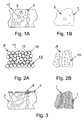
- Fig. 1A shows a filter body 1 of the same type as Cordierite Wall Flow Filters which, by it's nature, has a relatively low permeability caused by a large amount of uncontrolled pores, that often become blind cavities 3 and therefore, are of little use.
- the pores in this type of material are mainly created by a chemical reaction taking place during the sintering process, and not the packing relatively large grains together during the extrusion as is the case in the filter body described in PCT publication number WO 89/09648. This pore creation method is impossible to control to a higher degree of precision.
- SEM Sccanning Electron Microscope
- Fig. 1 B illustrates the number of open and useful pores 5 on the surface of the filter body 1 seen in Fig. 1A.
- a powder technology based wall flow filter body 8 is seen.
- This type of filter body 10 has an improved permeability compared to the type of filter body 1 seen in Fig. 1 due to a controlled pore size creation during manufacturing.
- the permeability of this filter body is 30-50% higher compared to non powder technology based Wall Flow Filters, such as the filter body 1 seen in Fig. 1, as the particles 10 constituting this filter body 8 have the same size and the contact points 12 connect all the particles 10 together only at the contact points 12.
- SEM investigations show a large number of open and useful pores 14, typically, this number is twice that of the filter body 1 seen in Fig. 1.
- Fig. 2B illustrates the number of open and useful pores 14 on the surface of the filter body 8 seen in Fig. 2A.
- FIG. 3 the position of a catalytically active coating 7 on filter body 1 as seen in Fig. 1 is seen. No surface-increasing coat is applied on this filter body 1.
- a catalytically active coating 16 on a powder technology based filter body 8 as seen in Fig. 2A is seen.
- This coating 16 may be positioned on top of a surface-increasing coating. Both these coatings cover every particle in the filter body with a controlled layer thickness so that no pores in the filter body 8 is blocked. No increase in pressure drop is measured when only the surface-Increasing coating is applied.
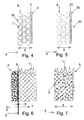
- Fig. 5 shows a preferred embodiment of a membrane 20 on a filter body as seen in Fig. 2A.
- the membrane 20 is added to the gas outlet side 22 of the filter body 8.
- the membrane 20 preferably covers the complete down stream, outlet side 22 surface of the filter body 8.
- the membrane 20 is formed by a number of particles 21, which are positioned in the outer parts of the gas outlet side 22 of the filter body.
- the membrane 20 may consist of a multi layer type with increasing pore size towards to the base structure of the filter body 8.
- the membrane 20 preferably only covers the outlet side 22.
- the gas flow including the soot, enters the open porosity of the filter body 8 and penetrates into the wall until it is slightly restricted for further penetration through the filter body 8 by the membrane 20.
- the porous filter wall 1 receives the gas flow 4 in one direction and accumulates the soot /carbon particles 2 on the top surface of the monolith wall, characterised as a soot cake with a well-defined boundary within the filter material itself.
- the soot layer 2 starts combustion in the very thin boundary layer 3 only with intimate contact with the catalytic active coating and a sufficient temperature.
- carbon monoxide is generated as a result of the combustion and at the same time the oxygen concentration is reduced. Both gases follow the flow direction 7 and are expelled through the exhaust system.
- the heat generated by the combustion follows direction 7 and the distance from the combustion zone 3 to the unbumed soot increases fast.
- Fig. 7 This invention relies on an very open filter structure, where the gas flow 4 tries to pass the soot particles 2 through with low filtration efficiency. As no well-defined soot cake is generated the soot penetrates into the filter wall and there is no well-defined combustion zone. The combustion takes place inside the filter wall itself, or the combustion zone is on the very grain surface and creates a boundary layer 3 with now same thickness as the filter wall. The boundary layer is only well-defined relative to each wall grain surface and not to the filter wall surface. The membrane 5 on the filter wall outlet side ensures that the trapping efficiency is kept high.
- Silicon carbide powder technology substrates may be manufactured using a continuous extrusion process.
- the compound may be composed of 69-72 wt% inexpensive, commercially available, large size Mesh 180 SIKA I grinding grain or powder size 75-105 ⁇ m from Arendal in Norway and 4-13 wt% ultra fine SiC, mixed into a plastic paste composed of 4-6 wt% Methyl Cellulose from Hoechst, 8-25 wt% water and 0-12 wt% ethanol.
- the paste may be extruded in a water cooled single screw auger extruder with vacuum chamber, into a honeycomb die heads. Extrusion speed may be from 1.5-2 meter pr. minute.
- the structure After a very high temperature sintering process, typically at a temperature above 2200°C, in a protective atmosphere, such as Argon, the structure becomes a low density, rigid and highly porous filter body.
- a protective atmosphere such as Argon
- the preferred shape of the filter body is at present the so-called honeycomb structure.
- This filter design has a matrix of thin, interconnected walls which define a multiplicity of cells and which have interconnected open pores of very controlled size.
- the porosity is high and sufficient to enable the fluid/gas to flow completely through the thin walls in their narrow dimensions, between adjoining cells and through the thin walls in their longer dimensions between adjoining or neighbouring cells and to substantially restrict the particles in the gas from flowing through the filter body.
- Each channel is closed in one end and neighbouring channels are closed at alternate ends, forming a chess-board like pattern, generating a Wall Flow Filter.
- SiC (silicon carbide) based filter material The properties of the SiC (silicon carbide) based filter material are characterised by an extremely high thermal conductivity (10-30 W/m 2 K), giving a very high thermal shock resistance. SiC decomposing point is around 700°C higher than melting point for Cordierite (1300°C). Expansion of SiC is 3.5-4 x 10 -6 /K.
- the high strength is obtained as the result of the ultra-fine SiC powder evaporating at the high sintering temperature and condensing in the grain contact points between the larger Mesh 180 grain.
- the structure becomes pure SiC.
- Wall Flow Filters produced from a powder having a very controlled grain size are characterised by an extremely homogeneous and controlled pore size and pore size distribution.
- a pore size measured to be 50 my gives a filtration efficiency, without a membrane, measured to be higher than 65%.
- the permeability is about 50% higher than that of a Coming Cordierite EX-66 structure having a filtration efficiency of approximately 70-80%.
- the applied wash coat may consist of an alumina/water slurry with added dispersing agents.
- alumina powder source Alcoa A16-sg (particle size: 40-80% within Mesh 200, corresponding to about 63 ⁇ m, surface area 5 m 2 /g, green density 2.12 g/cm 3 , analysis 99.8% pure Al 2 O 3 ) can be used.
- a commercially available dispersing agent such as DARVA C or Dispex from R. T. Van der Bilt CO, Int. may be used.
- the coating may be applied by two different methods as described here: A slurry with a relatively low alumina content can be used when the coat is applied simply by filling up the filter body with the slurry.
- Excess slurry is decantered off.
- the alumina content in the slurries used is in the range of 55-70% by weight.
- the coat can be applied by the use of vacuum or compressed air
- the filter is filled with a slurry containing 65-80 % alumina by weight.
- the excess slurry is driven out by applying vacuum or compressed air to one end of the substrate.
- the applied wash coat may be sintered in an oxidizing atmosphere in the temperature range of 1100-1500°C, preferably at 1200°C, for 1 hour.
- a fibre membrane coating may be deposited in a very thin layer 0,01-1 mm, preferably 0.05-0.2 mm, and with a mean pore size in the range of 2-20 ⁇ m, such as 5-10 ⁇ m. A separation efficiency as high as 95-99% for soot can be reached.
- the fibres used may be Almax alumina fibers, but also a wide variety of other fibers can be used.
- the dimensions of the fibers used may be: 10 ⁇ m diameter and 500 ⁇ m fiber length, but as mentioned above, the fibres will preferably be small, such as with a length of 1/50-1/100 of the channel width.
- a slurry containing Alcoa A16 sg alumina powder and Almax fibers in the ratio 0.1-5, preferably 0.2-0.5, may be applied by the same techniques as used in the application of wash coats.
- the slurry may be dispersed by the use of commercial dispersing agents, such as the above-mentioned dispersing agents.
- As a binding agent 4-7 wt% Methyl Cellulose from Hoechst may be used.
- the coatings may be sintered in an oxidizing atmosphere in the temperature range 1300-1500°C, preferably 1350-1450°C.
- a granule coating consisting of alumina/SiC can be used instead of the fiber based coating.
- the thickness of this membrane may be 0.01-1 mm, such as 0.05-0.15 mm.
- the alumina content may, as before, be Alcoa A16 sg.
- commercial grades of SiC such as Mesh 360, 400, 600 and 800 may beused. Preferably, Mesh grade 400 and 600 are used.
- Alumina/SiC ratio may be in the range 0.01-5 preferably 0.15-0.35.
- Commercially available dispersing agents may be used, such as the above-mentioned dispersing agents.
- binding agent 4-6 wt% Methyl Cellulose MH-300 from Hoechst may be used.
- the coating may be applied as mentioned above.
- the coat is sintered in an oxidising environment in the temperature range of 1100-1500°C preferably 1200-1300°C.
- the thickness of the applied membrane will depend on the porosity and inner structure of the porous filter body to receive the membrane.
- a catalytically active coating may be placed directly on the wash coat surface in order to act as an oxidation temperature reducing element.
- This coating may be deposited as a slurry containing the active material as submicron or ultra fine powder and the carrier may be water as a non-organic solution.
- the catalytically active material may be from the platinum element group.
- the active substance may be soluble in a fluid and the fluid being flushed through the substrate to a given weight increase.
- the amount of catalytically active material may, e.g., give a weight increase of 3 gram/liter substrate.
- the complete diesel filter will have a constant trapping efficiency of at least 98% and a considerably lower pressure drop than known systems having the same pressure drop.
- the regeneration temperature of this filter is envisaged to be of the order of 100°C lower than systems known per se.
- a series of different oxide-based ceramic substrates may be manufactured from Cordierite, Spodumene and Mullite compositions after similar methods.
- the ceramic precursors are listed in Table 1. Ceramic precursors. wt% Mix A Mix B Mix C Cordierite Spodumene Mullite China Clay gr. E (APS 2-3) 40.4 65.8 51.5 Talc (APS 1-4) 43.6 - - Al 2 O 3 CT 3000 SG (APS 0.4-0.6) 16.0 - 48.5 SiO 2 Fyleverken (APS 3-6) - 15.3 - Li 2 CO 3 anal. qual. (APS 3-6) - 18.9 -
- a methyl-hydroxy-ethyl-cellulose may be used (Tylose MH 300 P from Hoechst).
- the precursors may be calcinated/sintered to a grog and crushed into a coarse grained partly porous powder with a particle size similar to FEPA Mesh 180.
- the green body compounds may be composed according to Table 2 and mixed dry for 30 min. Ethanol is added and after another 10 min of mixing the water is introduced. Another 30 min. of mixing remains.
- a filler of polystyrene spheres (Shell N 2000) is added along with the dry raw materials. Selected size fractions of 30-50 ⁇ m are used. The spheres will pack to a dry tap porosity of 40 vol% which will result in a max. filler/compound ratio of 0.68.
- the compound is extruded in a single screw auger extruder with vacuum chamber, into the die head.
- the extruded bodies are dried at ambient temperature and controlled humidity and sintered in an electrical furnace with normal atmosphere according to Table 2.
- the structure becomes a low density, rigid and highly porous filter element.
- the pores have controlled pore size and the material has good properties for a further coating and addition of a membrane to optimise the high efficiency soot filter for diesel engines.
- a wash coat is deposited as described in example 1.
- the fibre membrane coating is very thin, 0.05-0.2 mm thick and has a mean pore size in the range of 5-10 ⁇ m. It is envisaged that a separation efficiency as high as 95-99% for soot can be reached.
- the fibres used are Almax alumina fibers. The dimensions of these fibers may be: 10 ⁇ m diameter and 0.5 mm fiber length, but as mentioned above, shorter fibres are highly preferred.
- a slurry containing Alcoa A16 sg alumina powder and Almax fibers in the ratio 0.1-5, preferably 0.2-0.5 was applied by the same techniques as used in the application of wash coats. The slurry se dispersed by the use of commercial dispersing agents.
- binding agent 4-7 wt% Methyl Cellulose from Hoechst is used.
- the coatings are sintered in oxidizing atmospheres in the temperature range 1300-1500°C, preferably 1350-1450°C.
- An active coating is applied as in example 1.
- a series of different oxide-based ceramic powder technology substrates are manufactured from Cordierite, Spodumene and Mullite compositions after similar methods.
- the ceramic precursors are listed in Table 3. Ceramic precursors. wt% Mix A Mix B Mix C Cordierite Spodumene Mullite China Clay grade E (APS 2-3) 40.4 65.8 51.5 Talc (APS 1-4) 43.6 - - Al 2 O 3 CT 3000 SG (APS 0.4-0.6) 16.0 - 48.5 SiO 2 Fyleverken (APS 3-6) - 15.3 - Li 2 CO 3 anal. qual. (APS 3-6) - 18.9 -
- a methyl-hydroxy-ethyl-cellulose is used (Tylose MH 300 P from Hoechst).
- Te MH 300 P from Hoechst
- the precursors are calcined/sintered to a grog and crushed into a coarse grained partly porous powder with a particle size similar to FEPA Mesh 80. 1-20% ultra fine powder from the same material is added in a ratio of between 20:1 to 6:1.
- the green body compounds are composed according to Table 4 and mixed dry for 30 min. Ethanol is added and after another 10 min of mixing the water is introduced. Another 30 min. of mixing remains.
- the compound is extruded in a single screw auger extruder with vacuum chamber, into the honeycomb die head.
- the extruded bodies were dried at ambient temperature and controlled humidity and precision sintered in an electrical furnace between 10 and 400 minutes with normal oxidizing atmosphere according to Table 4.
- the structures become a low density, relatively rigid but highly porous filter element with the important, very controlled pore size and distribution for maximum and high permeability made possible by the powder technology.
- wash coat is applied in the same manner as described in example 1.
- the fibre membrane coating is very thin, a 0.05-0.2 mm thick membrane with mean pore size in the range of 5-10 ⁇ m. A separation efficiency as high as 95-99% for soot can be reached.
- the fibres used are Almax alumina fibers. The dimensions of these fibers may be: 10 ⁇ m diameter and 0.5 mm fiber length, but as mentioned above, it may be preferred to use considerably shorter fibres, such as fibres of a length of at the most 100 ⁇ m.
- a slurry containing Alcoa A16 sg alumina powder and Almax fibers in the ratio 0.1-5, preferably 0.2-0.5, is applied by the same technique as used in the application of wash coats. The slurry is dispersed by the use of commercial dispersing agents. As binding agent 4-7 wt% Methyl Cellulose from Hoechst is used.
- the coatings are sintered in oxidizing atmospheres in the temperature range 1300-1500°C, preferably 1350-1450°C.
- An active coating is applied as in example 1.
- the filter device becomes, by way of this new technique, an ultra high-flow exhaust gas filter with previously unattained low regeneration temperatures for the captured diesel soot, providing an uncomplicated, low cost alternative to reducing soot emissions from diesel powered vehicles. It is known by the experienced person skilled in the art of ceramics and fine powder/fibre technology that the methods disclosed can be varied in many ways and still result in the novel structures and methods disclosed herein.
Claims (16)
- Pöröser Filter zum Herausfiltern von Rußpartikeln aus Dieselmotorabgasen, wobei der Filterkörper ein Durchflußfilterkörper mit Wabenwandstruktur ist, in dem miteinander verbundene Filterwände, die jeweils eine Gaseinlaßfläche und eine Gasauslaßfläche aufweisen, mehrere Kanäle definieren, wobei jeder Kanal an einem Ende geschlossen ist und benachbarte Kanäle an abwechselnden Enden geschlossen sind, wobei die Filterwände aus einem Material gebildet werden, das auf miteinander verbundenen Metall- und/oder Keramikpartikeln basiert, wobei die Porosität der Filterwand durch miteinander verbundene Hohlräume gebildet wird, die zwischen den Metallund/oder Keramikpartikeln definiert sind, wobei die Partikel die Poren des Materials direkt definieren, wobei ein katalytisch aktives Material, das die Oxidation von Ruß katalysiert, auf mindestens einem Teil derjenigen Oberflächenabschnitte der Metall- und/oder Keramikpartikel aufgebracht ist, die zu den Hohlräumen hin freiliegen, und wobei eine poröse Membran mit einer Porengröße bereitgestellt wird, die kleiner ist als diejenige der porösen Filterwände, dadurch gekennzeichnet, daß die poröse Membran nur an der Gasauslaßseite der Filterwände angeordnet ist.
- Filterkörper nach Anspruch 1, wobei die Filterwände aus miteinander verbundenen SiC-Partikeln bestehen.
- Filterkörper nach Anspruch 1 oder 2, wobei die Filterstruktur der Filterwände mit einem Beschichtungsmaterial beschichtet ist, um die aktive Kontaktoberfläche der Filterstruktur zu vergrößern und eine Verankerung für die katalytisch aktive Beschichtung bereitzustellen.
- Filterkörper nach Anspruch 3, wobei die die Oberfläche vergrößernde Beschichtung durch Partikel gebildet wird, die mit den Partikeln verbunden sind, auf denen das Material der Filterwände basiert.
- Filterkörper nach Anspruch 3 oder 4, wobei die die Oberfläche vergrößernde Beschichtung eine Aluminiumoxid-Zwischenschicht ist.
- Filterkörper nach Anspruch 5, wobei die Aluminiumoxid-Zwischenschicht durch Zusatzstoffe stabilisiert wird, wie beispielsweise durch Elemente der Gruppe I-VI.
- Filterkörper nach einem der vorangehenden Ansprüche, wobei die Filterstruktur mit einem Beschichtungsmaterial beschichtet ist, um die effektive Oberfläche der Filterstruktur zu vergrößern, und mit einem katalytisch aktiven Beschichtungsmaterial, das auf Metallen, wie beispielsweise Ru, Rh, Pt, Pd, Ir, Ni, Cu, V, W, Y, Ce, Ti, Zi, oder Kombinationen oder Oxiden davon basiert.
- Filterkörper nach einem der vorangehenden Ansprüche, wobei die Keramik- und/oder Metallpartikel, auf denen das Material der Filterwand basiert, eine Partikelgröße im Bereich von 1 - 250 µm aufweisen.
- Filterkörper nach Anspruch 8, wobei die Keramikund/oder Metallpartikel, auf denen das Material der Filterwand basiert, eine Partikelgröße im Bereich von 10 - 150 µm aufweisen.
- Filterkörper nach einem der vorangehenden Ansprüche, wobei die Poren der Filterwände eine mittlere Porengröße im Bereich von 10 - 200 µm aufweisen.
- Filterkörper nach Anspruch 10, wobei die Poren der Filterwände eine mittlere Porengröße im Bereich von 40 - 80 µm aufweisen.
- Filterkörper nach einem der vorangehenden Ansprüche, wobei die Porosität der Filterwände im Bereich von 30 - 90% liegt, z.B. im Bereich von 40 - 75%.
- Filterkörper nach einem der vorangehenden Ansprüche, wobei die an der Gasauslaßseite der Filterwände angeordnete poröse Membran eine Dicke im Bereich von 0,05 - 0,4 mm aufweist.
- Filterkörper nach einem der vorangehenden Ansprüche, wobei die an der Gasauslaßseite der Filterwände angeordnete poröse Membran durch Metall- und/oder Keramikpartikel und/oder -fasern gebildet wird.
- Filterkörper nach Anspruch 14, wobei die Größe der Partikel und/oder Fasern kleiner ist als die Porengröße des Materials der Filterwände.
- Filterkörper nach einem der vorangehenden Ansprüche, wobei die mittlere Porengröße der an der Gasauslaßseite der Filterwände angeordneten porösen Membran im Bereich von 2 - 15 µm liegt.
Applications Claiming Priority (3)
| Application Number | Priority Date | Filing Date | Title |
|---|---|---|---|
| DK90298 | 1998-07-07 | ||
| DKPA199800902 | 1998-07-07 | ||
| PCT/DK1999/000390 WO2000001463A1 (en) | 1998-07-07 | 1999-07-07 | Diesel exhaust gas filter |
Publications (2)
| Publication Number | Publication Date |
|---|---|
| EP1094879A1 EP1094879A1 (de) | 2001-05-02 |
| EP1094879B1 true EP1094879B1 (de) | 2003-04-09 |
Family
ID=8098828
Family Applications (1)
| Application Number | Title | Priority Date | Filing Date |
|---|---|---|---|
| EP99932676A Expired - Lifetime EP1094879B1 (de) | 1998-07-07 | 1999-07-07 | Dieselabgasfilter |
Country Status (9)
| Country | Link |
|---|---|
| US (1) | US7179430B1 (de) |
| EP (1) | EP1094879B1 (de) |
| JP (1) | JP4427658B2 (de) |
| KR (1) | KR20010081994A (de) |
| AT (1) | ATE236700T1 (de) |
| AU (1) | AU4897299A (de) |
| BR (1) | BR9912563A (de) |
| DE (1) | DE69906741T2 (de) |
| WO (1) | WO2000001463A1 (de) |
Cited By (2)
| Publication number | Priority date | Publication date | Assignee | Title |
|---|---|---|---|---|
| DE102006038706A1 (de) * | 2006-08-18 | 2008-02-21 | Volkswagen Ag | Brennkraftmaschine mit Niederdruck-Abgasrückführung |
| CN101522281B (zh) * | 2006-11-30 | 2012-06-27 | 日立金属株式会社 | 陶瓷蜂窝过滤器及其制造方法 |
Families Citing this family (86)
| Publication number | Priority date | Publication date | Assignee | Title |
|---|---|---|---|---|
| JP2002530175A (ja) | 1998-11-20 | 2002-09-17 | コーニンクレッカ フィリップス エレクトロニクス エヌ ヴィ | コードレス走査ヘッドの充電器を備える超音波診断イメージングシステム |
| WO2002016532A1 (fr) * | 2000-08-22 | 2002-02-28 | Idemitsu Kosan Co., Ltd. | Additif pour filtre a particules diesel |
| JP2002242655A (ja) * | 2001-02-15 | 2002-08-28 | Ibiden Co Ltd | 排ガス中のパティキュレート捕集フィルタ |
| KR100419780B1 (ko) * | 2001-02-23 | 2004-02-21 | 한국에너지기술연구원 | 코팅층이 형성된 탄화규소 세라믹스 필터 제조방법 |
| KR100419779B1 (ko) * | 2001-02-23 | 2004-02-21 | 한국에너지기술연구원 | 집진용 고강도 탄화규소 세라믹스 필터의 제조방법 |
| JP2002295228A (ja) * | 2001-03-30 | 2002-10-09 | Ibiden Co Ltd | 排気ガス浄化フィルタ |
| DE60210293T2 (de) * | 2001-08-01 | 2006-10-12 | Johnson Matthey Plc | Benzinmotor mit abgasanlage zur verbrennung von partikeln |
| WO2003024892A1 (en) * | 2001-09-21 | 2003-03-27 | Stobbe Tech Holding A/S | Porous ceramic structures and a preparing method |
| DE10226108A1 (de) * | 2002-06-12 | 2004-01-08 | J. Eberspächer GmbH & Co. KG | Abgasanlage mit Partikelfilter für Dieselmotoren |
| US7022647B2 (en) * | 2002-08-05 | 2006-04-04 | Battelle Energy Alliance, Llc | Methods of fabricating cermet materials and methods of utilizing same |
| JP3874270B2 (ja) * | 2002-09-13 | 2007-01-31 | トヨタ自動車株式会社 | 排ガス浄化フィルタ触媒及びその製造方法 |
| DE10247946A1 (de) * | 2002-10-15 | 2004-04-29 | Robert Bosch Gmbh | Abgasnachbehandlungsanordnung |
| JP4404538B2 (ja) * | 2002-10-18 | 2010-01-27 | 日本碍子株式会社 | 排ガス浄化用炭化珪素質触媒体及びその製造方法 |
| JP4571775B2 (ja) * | 2002-10-23 | 2010-10-27 | 日本碍子株式会社 | 多孔質ハニカム構造体の製造方法、及びハニカム成形体 |
| US20080256936A1 (en) * | 2007-04-17 | 2008-10-23 | Geo2 Technologies, Inc. | Selective Catalytic Reduction Filter and Method of Using Same |
| US7468089B2 (en) * | 2002-11-04 | 2008-12-23 | Battelle Energy Alliance, Llc | Cermet materials |
| JP4197425B2 (ja) * | 2002-11-07 | 2008-12-17 | 日本碍子株式会社 | ハニカム構造体 |
| JP4567285B2 (ja) * | 2002-11-22 | 2010-10-20 | 日本碍子株式会社 | 排ガス浄化用触媒体 |
| DE10301033A1 (de) * | 2003-01-13 | 2004-07-22 | Hjs Fahrzeugtechnik Gmbh & Co. | Verfahren zum Fügen von porösen Metallteilen |
| DE10331049B4 (de) * | 2003-07-09 | 2010-04-08 | Saint-Gobain Industriekeramik Rödental GmbH | Verfahren zur Herstellung eines porösen Keramikkörpers, danach hergestellter poröser Keramikkörper und dessen Verwendung |
| JP4437785B2 (ja) * | 2003-08-12 | 2010-03-24 | 日本碍子株式会社 | 炭化珪素質触媒体の製造方法 |
| DE10343438B4 (de) * | 2003-09-15 | 2007-06-28 | Fraunhofer-Gesellschaft zur Förderung der angewandten Forschung e.V. | Verfahren zur Herstellung von keramischen Partikelfiltern und keramischer Partikelfilter |
| FR2860993B1 (fr) | 2003-10-16 | 2006-06-16 | Sicat | Filtre catalytique a base de carbure de silicium (b-sic) pour la combustion des suies issues des gaz d'echappement d'un moteur a combustion |
| WO2005044422A1 (ja) | 2003-11-07 | 2005-05-19 | Ibiden Co., Ltd. | ハニカム構造体 |
| JP2005296935A (ja) * | 2004-03-17 | 2005-10-27 | Toyota Central Res & Dev Lab Inc | 排ガスフィルタおよびその製造方法、並びに、排ガス処理装置 |
| US20080236145A1 (en) * | 2007-04-02 | 2008-10-02 | Geo2 Technologies, Inc. | Emission Control System using a Multi-Function Catalyzing Filter |
| JPWO2006001509A1 (ja) * | 2004-06-25 | 2008-04-17 | イビデン株式会社 | 多孔体の製造方法、多孔体及びハニカム構造体 |
| JP4796496B2 (ja) * | 2004-06-25 | 2011-10-19 | イビデン株式会社 | フィルタ、その製造方法及び排気浄化装置 |
| US7759276B2 (en) | 2004-07-23 | 2010-07-20 | Helsa-Automotive Gmbh & Co. Kg | Adsorptive formed body having an inorganic amorphous supporting structure, and process for the production thereof |
| DE102004040551A1 (de) | 2004-08-21 | 2006-02-23 | Umicore Ag & Co. Kg | Verfahren zur Beschichtung eines Wandflußfilters mit einer Beschichtungszusammensetzung |
| DE102004051376A1 (de) * | 2004-09-13 | 2006-03-30 | Matthias Mangold | Herstellungsverfahren für ein Abgasreinigungsmittel und Abgasreinigungsmittel |
| JP2006110485A (ja) * | 2004-10-15 | 2006-04-27 | Johnson Matthey Japan Inc | 排気ガス触媒およびそれを用いた排気ガス処理装置 |
| DE102005019000A1 (de) | 2005-04-22 | 2006-10-26 | Degussa Ag | Katalytisch beschichteter Träger, Verfahren zu dessen Herstellung und damit ausgestatteter Reaktor sowie dessen Verwendung |
| DE102005027649A1 (de) * | 2005-06-15 | 2006-12-21 | Robert Bosch Gmbh | Abgasnachbehandlungsanordnung und Verfahren zur Herstellung einer Abgasnachbehandlungsanordnung |
| US7867313B2 (en) | 2005-07-05 | 2011-01-11 | Helsa-Automotive Gmbh & Co. Kg | Porous β-SiC-containing ceramic molded article comprising an aluminum oxide coating, and method for the production thereof |
| EP1741685B1 (de) * | 2005-07-05 | 2014-04-30 | MANN+HUMMEL Innenraumfilter GmbH & Co. KG | Poröser beta-SiC-haltiger keramischer Formkörper und Verfahren zu dessen Herstellung. |
| US7211232B1 (en) * | 2005-11-07 | 2007-05-01 | Geo2 Technologies, Inc. | Refractory exhaust filtering method and apparatus |
| JP2007275704A (ja) * | 2006-04-03 | 2007-10-25 | Johnson Matthey Japan Inc | 排気ガス触媒およびそれを用いた排気ガス処理装置 |
| DE202006007876U1 (de) * | 2006-05-15 | 2007-09-20 | Bauer Technologies Gmbh | Optimierung von zellulären Strukturen, insbesondere für die Abgasreinigung von Verbrennungsaggregaten und andere Anwendungsbereiche |
| US7669719B2 (en) * | 2006-07-05 | 2010-03-02 | General Electric Company | Membrane structure and method of making |
| US8158195B2 (en) * | 2007-02-09 | 2012-04-17 | Nissan Motor Co., Ltd. | Catalytic converter and manufacturing method thereof |
| FR2916366B1 (fr) * | 2007-05-23 | 2009-11-27 | Saint Gobain Ct Recherches | Filtre a particules texture pour applications catalytiques |
| US8828325B2 (en) * | 2007-08-31 | 2014-09-09 | Caterpillar Inc. | Exhaust system having catalytically active particulate filter |
| US7897255B2 (en) * | 2007-09-06 | 2011-03-01 | GE02 Technologies, Inc. | Porous washcoat-bonded fiber substrate |
| US20090263303A1 (en) * | 2007-10-16 | 2009-10-22 | Aspen Products Group, Inc. | Purification Device and Method for Purifying a Fluid Stream |
| JP5215634B2 (ja) * | 2007-11-07 | 2013-06-19 | 本田技研工業株式会社 | 排ガス浄化装置 |
| JP2009183835A (ja) * | 2008-02-05 | 2009-08-20 | Ngk Insulators Ltd | ハニカムフィルタ及びその製造方法 |
| US8091337B2 (en) * | 2008-02-29 | 2012-01-10 | Corning Incorporated | Exhaust treatment device having a reactive compound and conditioning the device via endothermic reaction |
| JP5291966B2 (ja) | 2008-03-25 | 2013-09-18 | 日本碍子株式会社 | 触媒担持フィルタ |
| JP2009226375A (ja) | 2008-03-25 | 2009-10-08 | Ngk Insulators Ltd | 触媒担持フィルタ |
| JP5031647B2 (ja) | 2008-04-11 | 2012-09-19 | 日本碍子株式会社 | ハニカム構造体の製造方法 |
| US20100050874A1 (en) * | 2008-08-29 | 2010-03-04 | Walter Cullen Lucas | Exhaust after treatment system and method |
| JP5208897B2 (ja) * | 2008-10-09 | 2013-06-12 | 日本碍子株式会社 | ハニカムフィルタ |
| EP2364200A1 (de) | 2008-11-26 | 2011-09-14 | Corning Incorporated | Beschichtetes teilchenfilter und verfahren |
| KR101113148B1 (ko) * | 2009-02-13 | 2012-02-13 | 강미경 | 방한용 아기띠 |
| JP2010194430A (ja) | 2009-02-24 | 2010-09-09 | Toyota Central R&D Labs Inc | 触媒付パティキュレートフィルタ |
| US8512657B2 (en) | 2009-02-26 | 2013-08-20 | Johnson Matthey Public Limited Company | Method and system using a filter for treating exhaust gas having particulate matter |
| GB0903262D0 (en) | 2009-02-26 | 2009-04-08 | Johnson Matthey Plc | Filter |
| JP5524179B2 (ja) * | 2009-03-26 | 2014-06-18 | 日本碍子株式会社 | ハニカムフィルタ及びハニカムフィルタの製造方法 |
| DE102009033635B4 (de) * | 2009-07-17 | 2020-11-05 | Umicore Ag & Co. Kg | Katalytisch aktives Partikelfilter mit Schwefelwasserstoff-Sperrfunktion, seine Verwendung und Verfahren zur Entfernung von Stickoxiden und Partikeln |
| CN102574075B (zh) * | 2009-09-30 | 2015-11-25 | 住友大阪水泥股份有限公司 | 废气净化过滤器 |
| US20120186206A1 (en) * | 2009-09-30 | 2012-07-26 | Honda Motor Co., Ltd. | Exhaust gas purifying filter |
| US9273574B2 (en) | 2009-09-30 | 2016-03-01 | Sumitomo Osaka Cement Co., Ltd. | Exhaust gas purifying filter |
| GB201000019D0 (en) | 2010-01-04 | 2010-02-17 | Johnson Matthey Plc | Coating a monolith substrate with catalyst component |
| US20110179778A1 (en) * | 2010-01-27 | 2011-07-28 | Gm Global Technology Operations, Inc. | Method and apparatus for exhaust gas aftertreatment from an internal combustion engine |
| GB201100595D0 (en) * | 2010-06-02 | 2011-03-02 | Johnson Matthey Plc | Filtration improvements |
| JP5904646B2 (ja) | 2010-08-31 | 2016-04-13 | コーニング インコーポレイテッド | コーティングされたチャネルを有するセルラーセラミック物品及びその製法 |
| RU2474558C2 (ru) * | 2010-12-02 | 2013-02-10 | Российская Федерация, от имени которой выступает Государственная корпорация по атомной энергии "Росатом" | Способ получения керамических блочно-ячеистых фильтров-сорбентов для улавливания газообразных радиоактивных и вредных веществ |
| WO2012134518A1 (en) * | 2011-03-30 | 2012-10-04 | International Engine Intellectual Property Company, Llc | Ammonia canister connection device |
| US20140093442A1 (en) * | 2011-05-31 | 2014-04-03 | Johnson Matthey Public Limited Company | Dual Function Catalytic Filter |
| WO2013146594A1 (ja) * | 2012-03-29 | 2013-10-03 | 株式会社クボタ | セラミックフィルタ |
| WO2013145318A1 (ja) * | 2012-03-30 | 2013-10-03 | イビデン株式会社 | ハニカムフィルタ及びハニカムフィルタの製造方法 |
| JP5833740B2 (ja) * | 2012-03-30 | 2015-12-16 | イビデン株式会社 | ハニカムフィルタ |
| CN103566920B (zh) | 2012-08-01 | 2016-05-25 | 通用电气公司 | 物质和使用其的排气装置及方法 |
| DE102012220181A1 (de) | 2012-11-06 | 2014-05-08 | Fraunhofer-Gesellschaft zur Förderung der angewandten Forschung e.V. | Partikelfilter |
| CN104411928B (zh) * | 2012-11-13 | 2017-03-08 | 丰田自动车株式会社 | 内燃机的排气净化装置 |
| WO2014083642A1 (ja) * | 2012-11-28 | 2014-06-05 | トヨタ自動車株式会社 | 排気浄化フィルタ |
| GB201311615D0 (en) | 2013-06-03 | 2013-08-14 | Johnson Matthey Plc | Method of coating a substrate with a catalyst component |
| EP3138622B1 (de) * | 2015-02-02 | 2021-05-05 | Mitsui Mining & Smelting Co., Ltd. | Träger für abgasreinigungskatalysator sowie abgasreinigungskatalysator |
| EP3442702B2 (de) | 2016-04-11 | 2024-03-13 | Johnson Matthey Public Limited Company | Verfahren zum beschichten eines substrats mit einem partikelstabilisierten schaumstoff |
| JP6645337B2 (ja) * | 2016-04-20 | 2020-02-14 | 株式会社オートネットワーク技術研究所 | 接続端子および接続端子対 |
| MX2020002230A (es) * | 2017-08-28 | 2020-07-20 | Corning Inc | Cuerpo de panal con estructura de panal radial con componente estructural de transicion y troquel de extrusion del mismo. |
| US11161782B2 (en) | 2017-11-30 | 2021-11-02 | Corning Incorporated | Method of increasing IOX processability on glass articles with multiple thicknesses |
| JP7061491B2 (ja) * | 2018-03-27 | 2022-04-28 | 日本碍子株式会社 | ハニカム構造体 |
| GB201911702D0 (en) | 2019-08-15 | 2019-10-02 | Johnson Matthey Plc | Particulate filters |
| CN111871070B (zh) * | 2019-11-12 | 2021-02-19 | 南京工业大学 | 一种一体化滤料 |
Family Cites Families (7)
| Publication number | Priority date | Publication date | Assignee | Title |
|---|---|---|---|---|
| US4857088A (en) | 1986-12-23 | 1989-08-15 | Swiss Aluminum Ltd. | Filter for cleaning the exhaust gases from diesel engines |
| JPS63185425A (ja) * | 1987-01-28 | 1988-08-01 | Ngk Insulators Ltd | 排ガス浄化用セラミツクハニカムフイルタ |
| US4912076A (en) * | 1987-10-15 | 1990-03-27 | Swiss Aluminium Ltd. | Filter for cleaning exhaust gases of diesel engines |
| US4846906A (en) * | 1987-12-02 | 1989-07-11 | The Duriron Company, Inc. | Methods for the manufacture of porous ceramic shapes containing membraneous surfaces |
| EP0336883B1 (de) | 1988-04-08 | 1999-01-13 | Per Stobbe | Verfahren zur Herstellung eines porösen Filterkörpers |
| US5041407A (en) * | 1989-12-14 | 1991-08-20 | Allied-Signal Inc. | High-temperature three-way catalyst for treating automotive exhaust gases |
| JP3750178B2 (ja) * | 1995-04-05 | 2006-03-01 | 株式会社デンソー | 排ガス浄化用フィルタ及びその製造方法 |
-
1999
- 1999-07-07 EP EP99932676A patent/EP1094879B1/de not_active Expired - Lifetime
- 1999-07-07 WO PCT/DK1999/000390 patent/WO2000001463A1/en not_active Application Discontinuation
- 1999-07-07 BR BR9912563-3A patent/BR9912563A/pt not_active Application Discontinuation
- 1999-07-07 KR KR1020017000282A patent/KR20010081994A/ko not_active Application Discontinuation
- 1999-07-07 JP JP2000557902A patent/JP4427658B2/ja not_active Expired - Fee Related
- 1999-07-07 AU AU48972/99A patent/AU4897299A/en not_active Abandoned
- 1999-07-07 US US09/743,096 patent/US7179430B1/en not_active Expired - Fee Related
- 1999-07-07 AT AT99932676T patent/ATE236700T1/de not_active IP Right Cessation
- 1999-07-07 DE DE69906741T patent/DE69906741T2/de not_active Expired - Fee Related
Cited By (4)
| Publication number | Priority date | Publication date | Assignee | Title |
|---|---|---|---|---|
| DE102006038706A1 (de) * | 2006-08-18 | 2008-02-21 | Volkswagen Ag | Brennkraftmaschine mit Niederdruck-Abgasrückführung |
| US7921639B2 (en) | 2006-08-18 | 2011-04-12 | Volkswagen Aktiengesellschaft | Internal combustion engine having a low-pressure exhaust-gas recirculation |
| DE102006038706B4 (de) | 2006-08-18 | 2018-12-27 | Volkswagen Ag | Brennkraftmaschine mit Niederdruck-Abgasrückführung |
| CN101522281B (zh) * | 2006-11-30 | 2012-06-27 | 日立金属株式会社 | 陶瓷蜂窝过滤器及其制造方法 |
Also Published As
| Publication number | Publication date |
|---|---|
| EP1094879A1 (de) | 2001-05-02 |
| DE69906741D1 (de) | 2003-05-15 |
| WO2000001463A1 (en) | 2000-01-13 |
| BR9912563A (pt) | 2001-05-02 |
| JP2002519186A (ja) | 2002-07-02 |
| JP4427658B2 (ja) | 2010-03-10 |
| DE69906741T2 (de) | 2003-12-24 |
| AU4897299A (en) | 2000-01-24 |
| KR20010081994A (ko) | 2001-08-29 |
| ATE236700T1 (de) | 2003-04-15 |
| US7179430B1 (en) | 2007-02-20 |
Similar Documents
| Publication | Publication Date | Title |
|---|---|---|
| EP1094879B1 (de) | Dieselabgasfilter | |
| EP1403231B1 (de) | Verfahren zur herstellung eines porösen keramiksinterkörpers | |
| EP1437491B1 (de) | Filter Katalysator zur Reinigung von Abgasen | |
| US7517502B2 (en) | Honeycomb structural body | |
| JP4386830B2 (ja) | 排気ガス浄化用ハニカムフィルタ | |
| US7541006B2 (en) | Honeycomb structured body | |
| US7785695B2 (en) | Honeycomb structured body | |
| CN100443710C (zh) | 柴油发动机及其催化过滤器 | |
| EP1759754B1 (de) | Verfahren zur herstellung eines filters für abgasreinigungssystem | |
| JP5193437B2 (ja) | 排ガス浄化用触媒 | |
| WO2006035823A1 (ja) | ハニカム構造体 | |
| EP2286912A2 (de) | Katalysatorträgerwabe und Verfahren zu ihrer Herstellung | |
| US20090247399A1 (en) | Catalytic diesel particulate filter and manufacturing method thereof | |
| WO2006035822A1 (ja) | ハニカム構造体 | |
| KR101457238B1 (ko) | 개선된 매연 필터 | |
| US8388898B2 (en) | Ceramic filter element | |
| EP2108494B1 (de) | Herstellungsverfahren für eine Wabenstruktur | |
| US20060234858A1 (en) | Silicon carbide based catalyst material and method for preparation thereof | |
| US20080242535A1 (en) | Honeycomb Structural Body and Method of Fabricating the Same | |
| EP2614874B1 (de) | Wabenfilter | |
| KR20090106483A (ko) | 탄화 규소를 기초로 한 다공성 구조물을 얻는 방법 | |
| JP2022128501A (ja) | セラミックス多孔体及びその製造方法、並びに集塵用フィルタ | |
| JP2009236067A (ja) | ハニカム構造体およびそのハニカム構造体からなる触媒体 |
Legal Events
| Date | Code | Title | Description |
|---|---|---|---|
| PUAI | Public reference made under article 153(3) epc to a published international application that has entered the european phase |
Free format text: ORIGINAL CODE: 0009012 |
|
| 17P | Request for examination filed |
Effective date: 20010207 |
|
| AK | Designated contracting states |
Kind code of ref document: A1 Designated state(s): AT BE CH CY DE DK ES FI FR GB GR IE IT LI LU MC NL PT SE |
|
| 17Q | First examination report despatched |
Effective date: 20020517 |
|
| GRAH | Despatch of communication of intention to grant a patent |
Free format text: ORIGINAL CODE: EPIDOS IGRA |
|
| GRAH | Despatch of communication of intention to grant a patent |
Free format text: ORIGINAL CODE: EPIDOS IGRA |
|
| GRAA | (expected) grant |
Free format text: ORIGINAL CODE: 0009210 |
|
| RAP1 | Party data changed (applicant data changed or rights of an application transferred) |
Owner name: CORNING INCORPORATED |
|
| AK | Designated contracting states |
Designated state(s): AT BE CH CY DE DK ES FI FR GB GR IE IT LI LU MC NL PT SE |
|
| PG25 | Lapsed in a contracting state [announced via postgrant information from national office to epo] |
Ref country code: NL Free format text: LAPSE BECAUSE OF FAILURE TO SUBMIT A TRANSLATION OF THE DESCRIPTION OR TO PAY THE FEE WITHIN THE PRESCRIBED TIME-LIMIT Effective date: 20030409 Ref country code: LI Free format text: LAPSE BECAUSE OF FAILURE TO SUBMIT A TRANSLATION OF THE DESCRIPTION OR TO PAY THE FEE WITHIN THE PRESCRIBED TIME-LIMIT Effective date: 20030409 Ref country code: FI Free format text: LAPSE BECAUSE OF FAILURE TO SUBMIT A TRANSLATION OF THE DESCRIPTION OR TO PAY THE FEE WITHIN THE PRESCRIBED TIME-LIMIT Effective date: 20030409 Ref country code: CH Free format text: LAPSE BECAUSE OF FAILURE TO SUBMIT A TRANSLATION OF THE DESCRIPTION OR TO PAY THE FEE WITHIN THE PRESCRIBED TIME-LIMIT Effective date: 20030409 Ref country code: AT Free format text: LAPSE BECAUSE OF FAILURE TO SUBMIT A TRANSLATION OF THE DESCRIPTION OR TO PAY THE FEE WITHIN THE PRESCRIBED TIME-LIMIT Effective date: 20030409 |
|
| REG | Reference to a national code |
Ref country code: GB Ref legal event code: FG4D |
|
| REG | Reference to a national code |
Ref country code: CH Ref legal event code: EP |
|
| REG | Reference to a national code |
Ref country code: IE Ref legal event code: FG4D |
|
| PGFP | Annual fee paid to national office [announced via postgrant information from national office to epo] |
Ref country code: GB Payment date: 20030612 Year of fee payment: 5 |
|
| PG25 | Lapsed in a contracting state [announced via postgrant information from national office to epo] |
Ref country code: LU Free format text: LAPSE BECAUSE OF NON-PAYMENT OF DUE FEES Effective date: 20030707 Ref country code: IE Free format text: LAPSE BECAUSE OF NON-PAYMENT OF DUE FEES Effective date: 20030707 Ref country code: CY Free format text: LAPSE BECAUSE OF FAILURE TO SUBMIT A TRANSLATION OF THE DESCRIPTION OR TO PAY THE FEE WITHIN THE PRESCRIBED TIME-LIMIT Effective date: 20030707 |
|
| PG25 | Lapsed in a contracting state [announced via postgrant information from national office to epo] |
Ref country code: SE Free format text: LAPSE BECAUSE OF FAILURE TO SUBMIT A TRANSLATION OF THE DESCRIPTION OR TO PAY THE FEE WITHIN THE PRESCRIBED TIME-LIMIT Effective date: 20030709 Ref country code: PT Free format text: LAPSE BECAUSE OF FAILURE TO SUBMIT A TRANSLATION OF THE DESCRIPTION OR TO PAY THE FEE WITHIN THE PRESCRIBED TIME-LIMIT Effective date: 20030709 Ref country code: GR Free format text: LAPSE BECAUSE OF FAILURE TO SUBMIT A TRANSLATION OF THE DESCRIPTION OR TO PAY THE FEE WITHIN THE PRESCRIBED TIME-LIMIT Effective date: 20030709 Ref country code: DK Free format text: LAPSE BECAUSE OF FAILURE TO SUBMIT A TRANSLATION OF THE DESCRIPTION OR TO PAY THE FEE WITHIN THE PRESCRIBED TIME-LIMIT Effective date: 20030709 |
|
| PG25 | Lapsed in a contracting state [announced via postgrant information from national office to epo] |
Ref country code: MC Free format text: LAPSE BECAUSE OF NON-PAYMENT OF DUE FEES Effective date: 20030731 |
|
| PGFP | Annual fee paid to national office [announced via postgrant information from national office to epo] |
Ref country code: DE Payment date: 20030731 Year of fee payment: 5 |
|
| PGFP | Annual fee paid to national office [announced via postgrant information from national office to epo] |
Ref country code: BE Payment date: 20030811 Year of fee payment: 5 |
|
| NLV1 | Nl: lapsed or annulled due to failure to fulfill the requirements of art. 29p and 29m of the patents act | ||
| REG | Reference to a national code |
Ref country code: CH Ref legal event code: PL |
|
| PG25 | Lapsed in a contracting state [announced via postgrant information from national office to epo] |
Ref country code: ES Free format text: LAPSE BECAUSE OF FAILURE TO SUBMIT A TRANSLATION OF THE DESCRIPTION OR TO PAY THE FEE WITHIN THE PRESCRIBED TIME-LIMIT Effective date: 20031030 |
|
| ET | Fr: translation filed | ||
| PLBE | No opposition filed within time limit |
Free format text: ORIGINAL CODE: 0009261 |
|
| STAA | Information on the status of an ep patent application or granted ep patent |
Free format text: STATUS: NO OPPOSITION FILED WITHIN TIME LIMIT |
|
| 26N | No opposition filed |
Effective date: 20040112 |
|
| REG | Reference to a national code |
Ref country code: IE Ref legal event code: MM4A |
|
| PG25 | Lapsed in a contracting state [announced via postgrant information from national office to epo] |
Ref country code: GB Free format text: LAPSE BECAUSE OF NON-PAYMENT OF DUE FEES Effective date: 20040707 |
|
| PG25 | Lapsed in a contracting state [announced via postgrant information from national office to epo] |
Ref country code: BE Free format text: LAPSE BECAUSE OF NON-PAYMENT OF DUE FEES Effective date: 20040731 |
|
| BERE | Be: lapsed |
Owner name: *CORNING INC. Effective date: 20040731 |
|
| PG25 | Lapsed in a contracting state [announced via postgrant information from national office to epo] |
Ref country code: DE Free format text: LAPSE BECAUSE OF NON-PAYMENT OF DUE FEES Effective date: 20050201 |
|
| GBPC | Gb: european patent ceased through non-payment of renewal fee |
Effective date: 20040707 |
|
| PG25 | Lapsed in a contracting state [announced via postgrant information from national office to epo] |
Ref country code: IT Free format text: LAPSE BECAUSE OF NON-PAYMENT OF DUE FEES Effective date: 20050707 |
|
| BERE | Be: lapsed |
Owner name: *CORNING INC. Effective date: 20040731 |
|
| PGFP | Annual fee paid to national office [announced via postgrant information from national office to epo] |
Ref country code: FR Payment date: 20130717 Year of fee payment: 15 |
|
| REG | Reference to a national code |
Ref country code: FR Ref legal event code: ST Effective date: 20150331 |
|
| PG25 | Lapsed in a contracting state [announced via postgrant information from national office to epo] |
Ref country code: FR Free format text: LAPSE BECAUSE OF NON-PAYMENT OF DUE FEES Effective date: 20140731 |