EP1093037B1 - Méthode et dispositif pour commander des procédés dans un véhicule - Google Patents
Méthode et dispositif pour commander des procédés dans un véhicule Download PDFInfo
- Publication number
- EP1093037B1 EP1093037B1 EP00120965A EP00120965A EP1093037B1 EP 1093037 B1 EP1093037 B1 EP 1093037B1 EP 00120965 A EP00120965 A EP 00120965A EP 00120965 A EP00120965 A EP 00120965A EP 1093037 B1 EP1093037 B1 EP 1093037B1
- Authority
- EP
- European Patent Office
- Prior art keywords
- processor
- processors
- address
- signal
- access
- Prior art date
- Legal status (The legal status is an assumption and is not a legal conclusion. Google has not performed a legal analysis and makes no representation as to the accuracy of the status listed.)
- Expired - Lifetime
Links
Images
Classifications
-
- G—PHYSICS
- G05—CONTROLLING; REGULATING
- G05B—CONTROL OR REGULATING SYSTEMS IN GENERAL; FUNCTIONAL ELEMENTS OF SUCH SYSTEMS; MONITORING OR TESTING ARRANGEMENTS FOR SUCH SYSTEMS OR ELEMENTS
- G05B19/00—Programme-control systems
- G05B19/02—Programme-control systems electric
- G05B19/04—Programme control other than numerical control, i.e. in sequence controllers or logic controllers
- G05B19/042—Programme control other than numerical control, i.e. in sequence controllers or logic controllers using digital processors
- G05B19/0421—Multiprocessor system
Definitions
- the invention relates to methods and apparatus for controlling operations in a vehicle, wherein at least two processors access at least one storage means, according to the preambles of the independent claims.
- DE 41 29 809 A1 shows a multi-computer system, in particular for controlling processes in motor vehicles.
- at least two computers access together to a storage means.
- the storage means is divided into at least two areas. On the first memory area accesses a first computer read only and a second computer only write. On the second memory area of the second computer accesses only reading and the first computer only write.
- the computers are synchronized so that they access the storage means in the same way at the same time. Since both computers either read or write on access decoupled memory areas, a collision, so a read or write access to the same address in the storage means is prevented. However, this synchronization can lead to unwanted waiting times in program execution.
- the invention is based on a method and a device for controlling operations in a vehicle, wherein at least two processors access at least one memory means and prevent a simultaneous read and / or write access at least two processors to the same address of the memory means in a program execution becomes.
- at least two processors access at least one memory means and prevent a simultaneous read and / or write access at least two processors to the same address of the memory means in a program execution becomes.
- it is recognized by an address comparison before the actual read and / or write access that the at least two processors will access the same address.
- a first signal is transmitted to the first processor and a second signal is transmitted to a second processor and the program execution of at least one of the at least two processors is prevented by the respective signal.
- the program execution of the at least first of the at least two computers is inhibited by the respective signal until different addresses are again detected in the address comparison and / or the read and / or write access of the at least second processor is terminated, the access of at least two processors temporally decoupled to the at least one storage means.
- the program execution of at least one of the at least two processors is prevented by the respective signal for a predeterminable and / or time determinable from the address comparison.
- the read and / or write accesses of the at least two processors to addresses of the at least one memory means can be carried out asynchronously, ie at arbitrary times.
- both subsystems in particular both processors work asynchronously so with full performance and exchange information, higher data throughputs can be achieved.
- the processors work independently and access the common storage means at arbitrary times.
- the invention can also be used in a synchronized operation of the at least two processors.
- the additional burden for the duration is very low, since only in the impending conflict, a temporal access decoupling occurs, but rarely occurs. This ensures the highest possible up-to-dateness of the data in the memory.
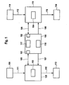
- FIG. 1 shows schematically a system with at least two processors which access a storage means. Based on the waveform of the processors and a comparison means to the program processing in at least To prevent a processor, the inventive concept is explained in Figure 2.
- FIG. 1 shows a system for controlling processes in a vehicle.
- 119 represents a first subsystem, in particular a control unit 119 with a processor 104, in particular a CPU.
- a processor 104 in particular a CPU.
- measured or otherwise determined operating variables from an element 110 which corresponds to a measuring device, a further control unit, etc. supplied via interface 112 to the subsystem 119.
- These signals which are transmitted via the interface 112 thus correspond to measured operating variables or can be derived from these signals such operating variables.
- the processor unit 104 forms in the context of programs or control functions implemented in at least one memory in the form of program code, values for the control variables to be output, which control elements, in particular represented by element 114, in FIG Setting the sense of a given control strategy.
- the processes to be controlled in this case are part of a transmission control, control of the chassis (ABS, ASR, ESP, etc.), in particular the brake, control of comfort and safety electronics, control of a drive unit, in particular an internal combustion engine, control of the drive train, or other Control operations included in the vehicle.
- Subsystem 119 as well as subsystem 120 are preferably a control unit for controlling a drive unit, in particular an internal combustion engine of a vehicle.
- a control unit for controlling a drive unit, in particular an internal combustion engine of a vehicle.
- signals which measured Operating variables of the drive unit, the drive train and / or the vehicle correspond or from which such operating variables can be derived from the elements 109 and 110, in particular measuring elements or other control units via the interface 111 and 112, the subsystems 119 and 120 supplied.
- these subsystems can correspond only to the processor units or processors 103 and 104 or contain further elements such as, for example, memory elements, in particular a program memory, further interfaces or the like.
- the processors 103 and 104 or the subsystems 119 and 120 can be housed in a control unit as well as they can be distributed to different control devices.
- the signal or the operating variables supplied by the elements 109 and 110 are, in particular, those operating variables which can be evaluated for controlling a drive unit, in particular an internal combustion engine. Signals are also output via the interfaces 115 and 116, which actuate actuating elements or actuators for setting at least one operating variable of the vehicle, in particular a drive unit.
- the respective processor unit 104 or 103 thus forms the control variables for the actuating elements 113 and 114, respectively, in accordance with a control strategy.
- the position of a driver-actuated position is known Operating element detected, evaluated and determined a target value for a torque of the drive unit.
- setpoint values received via the interfaces 111 and 112 for example, of other control systems, such as a traction control, a transmission control, etc. as well as internally formed setpoints (limits, etc.) for determining a setpoint, eg for the torque.
- This is then converted in a preferred embodiment of an internal combustion engine control into a desired value for the position of the throttle valve, which is set as part of a bearing control loop.
- further power-determining functions are provided, for example, control of a turbocharger, exhaust gas recirculation, an idle speed control, etc.
- the programs required for this purpose can be accommodated once in program memories contained in the subsystems 119 and 120, respectively, or in a central memory 100.
- data can be stored either in the subsystems themselves, ie in 119 or 120 in memory elements or in a common memory Memory element 100. If programs and / or data are stored in a central memory element 100, both subsystems or in particular processors 103 or 104 access this central memory element 100. This is done via the ports 101 and 102 by means of the interfaces 105 and 106. Via the interfaces 105 or 106 is thus written by the processors 103 and 104 in memory element 100 and read from these.
- the bidirectional transmission of information can be done serially as well as in parallel.
- the parallel transmission of the information has the advantage that the address is very quickly available for an address comparison.
- the memory element 100 can be a dual-port RAM for coupling between the processors or, for example, can also be designed as a conventional, ie single-port RAM with an upstream multiplexer. In principle, however, any volatile or nonvolatile memory can be used.
- the memory element 100 contains an address comparator 117.
- the address comparator circuit 117 serves to detect the case when the two processors 103 and 104 access the same address. In this case, the two addresses are compared via port 101 or 102, for example via a comparator arrangement, and depending on the result of the comparison, signals are transmitted to the processors 103 and 104, respectively. These signals are transmitted via interfaces 107 and 108, respectively. In the simplest case, a stop signal is transmitted to the processor to be stopped via the interface 107 or 108.
- Element 118 serves to carry out the coordination, which processor is to be stopped, that is to which processor to which signal is to be transmitted.
- These Coordination circuit 118 is meaningfully also accommodated in the memory element 100 or together with it in a component.
- it is determined via the address comparison in the address comparator 117 that the two processors 103 and 104 want to access an identical address.
- the access does not have to be absolutely simultaneous.
- Equality in this case also means within a certain, predeterminable time window.
- Several variants are possible. Once, it is possible to wait for the data to be sent following the address transfer until the address of the second processor is completely compared with the first one. However, this has the disadvantage that it creates waiting times.
- Another possibility is to determine when creating an address only whether the other processor also plans an access. If an address is already present through the respective other processor, then the address is first compared before the second one is allowed to begin access. If there is no further address of the other processor at the time of the address transmission, the read access of the first accessing processor is automatically started after transmission of the complete address. These checks are performed in the comparison circuit 117.
- a DPRAM can then be used for coupling between the microprocessors, the signals of the DPRAM then being routed to the processors without additional hardware and being used to automatically trigger the impending conflict in quasi-simultaneous access to the same DPRAM memory cell to decouple in time.
- at least one processor is temporarily halted or the program execution is inhibited by this processor.
- a simple signal is output by the coordination circuit 118.
- the addresses, chip enable signals, output enable signals, read and write signals of the two ports 101 and 102, individually or in combination in the Coordination logic 118 are used to form the signals via interfaces 107 and 108.
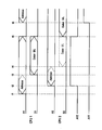
- processor 103 starts, in this case CPU1, with the transmission of the access address.
- a signal A1 is transmitted via interface 105 and port 101 to memory element 100.
- processor 104 here referred to as CPU2
- the associated signal is referred to here as A2.
- the comparison circuit 117 is thus determined at the time t2 that at the same time two addresses, possibly the same addresses are accessed.
- a signal AV2 is thus initiated at the time t2.
- the processor 103 Since no further address was applied at the time t1, the processor 103, that is to say CPU1, starts the write / read access (S / L) of the above address at the time t3 following the complete transmission of the address, that is to say the signal A1.
- a second signal AV1 is formed which is intended for the respective other processor.
- processor 104 ie CPU2 has the address Signal A2 completely transferred and would start with the read / write access, ie signal D2 to memory element 100. If it is determined in the address comparator 117 that the two addresses are thus equal to the signals A1 and A2, the signal AV2 is output by the coordination circuit 118 to the CPU2, that is, the processor 104. This prevents access to the memory location.
- AV1 is output via interface 108 at the processor 103, ie CPU1, which allows further access.
- CPU1 wants to access the same address again. However, since CPU2 is currently in the access S / L to this address, the signal AV1 is set and output to CPU1, ie processor 103 via line 107 by the coordination circuit 118. As a result, the access by processor 103, so CPU1 is in turn prevented.
- the advantage of the invention is in particular that both subsystems 119 and 120 or the processors 104 and 103 asynchronously and thus virtually work with full performance and can exchange information.
- a storage device with more than two simultaneous access possibilities can also be used according to the invention, in particular a quadripole RAM, that is to say a volatile memory with in this case especially four simultaneous access possibilities by e.g. two or four processors.
Claims (7)
- Procédé de commande d'opérations dans un véhicule, selon lequel au moins deux processeurs (103, 104) accèdent à au moins un moyen de mémoire, en empêchant un accès en lecture et/ou en écriture simultané des processeurs à la même adresse du moyen de mémoire pendant une exécution de programme,
caractérisé en ce qu'
on reconnaît la même adresse par comparaison d'adresses, et on transmet au moins un signal en fonction de la comparaison d'adresses à au moins un processeur, le signal bloquant l'exécution du programme du processeur. - Procédé selon la revendication 1,
caractérisé en ce qu'
on transmet un premier signal à un premier processeur et un deuxième signal à un deuxième processeur, et le signal bloque l'exécution du programme d'au moins un processeur. - Procédé selon la revendication 1,
caractérisé en ce que
l'exécution du programme d'au moins l'un des au moins deux processeurs est bloquée par le signal respectif jusqu'à ce que des adresses différentes soient à nouveau reconnues lors de la comparaison d'adresses et/ou l'accès en lecture et/ou en écriture de l'au moins un deuxième processeur soit terminé. - Procédé selon la revendication 1,
caractérisé en ce que
l'exécution du programme d'au moins l'un des au moins deux processeurs est bloquée par le signal respectif pour une durée pouvant être prédéfinie et/ou déterminée à partir de la comparaison d'adresses. - Procédé selon la revendication 1,
caractérisé en ce que
les accès en lecture et/ou en écriture à des adresses du moyen de mémoire pendant une exécution de programme d'au moins deux processeurs s'effectuent de façon asynchrone, donc à des moments quelconques. - Procédé selon les revendications 1 et 2,
caractérisé en ce que
l'exécution de programme de l'au moins un deuxième processeur est bloquée si l'accès en lecture et/ou en écriture du premier processeur a été détecté simultanément à la même adresse à l'aide de la comparaison d'adresses avant l'accès en lecture et/ou en écriture du deuxième processeur. - Dispositif de commande de processus dans un véhicule, comprenant au moins deux processeurs (105, 104) et au moins un moyen de mémoire (100), dans lequel au moins deux processeurs accèdent à au moins un moyen de mémoire, et un accès en lecture et/ou en écriture simultané des processeurs à la même adresse du moyen de mémoire est empêché pendant une exécution de programme,
caractérisé en ce qu'
il comprend des premiers moyens (119) qui reconnaissent la même adresse par comparaison d'adresses, et des deuxièmes moyens (118) qui, en fonction de la comparaison d'adresses, transmettent un premier signal au premier processeur et un deuxième signal au deuxième processeur et bloquent l'exécution du programme d'au moins l'un des processeurs par le signal respectif.
Applications Claiming Priority (2)
| Application Number | Priority Date | Filing Date | Title |
|---|---|---|---|
| DE19949051 | 1999-10-11 | ||
| DE19949051A DE19949051A1 (de) | 1999-10-11 | 1999-10-11 | Verfahren und Vorrichtung zur Steuerung von Vorgängen in einem Fahrzeug |
Publications (3)
| Publication Number | Publication Date |
|---|---|
| EP1093037A2 EP1093037A2 (fr) | 2001-04-18 |
| EP1093037A3 EP1093037A3 (fr) | 2004-01-21 |
| EP1093037B1 true EP1093037B1 (fr) | 2006-08-30 |
Family
ID=7925303
Family Applications (1)
| Application Number | Title | Priority Date | Filing Date |
|---|---|---|---|
| EP00120965A Expired - Lifetime EP1093037B1 (fr) | 1999-10-11 | 2000-09-27 | Méthode et dispositif pour commander des procédés dans un véhicule |
Country Status (4)
| Country | Link |
|---|---|
| US (1) | US6356813B1 (fr) |
| EP (1) | EP1093037B1 (fr) |
| JP (1) | JP2001166982A (fr) |
| DE (2) | DE19949051A1 (fr) |
Families Citing this family (14)
| Publication number | Priority date | Publication date | Assignee | Title |
|---|---|---|---|---|
| DE10113917B4 (de) * | 2001-03-21 | 2019-05-23 | Robert Bosch Gmbh | Verfahren und Vorrichtung zur Überwachung von Steuereinheiten |
| JP4785320B2 (ja) * | 2002-01-31 | 2011-10-05 | キヤノン株式会社 | 記憶装置 |
| US20050002354A1 (en) * | 2003-07-02 | 2005-01-06 | Kelly Thomas J. | Systems and methods for providing network communications between work machines |
| US20050005167A1 (en) * | 2003-07-02 | 2005-01-06 | Kelly Thomas J. | Systems and methods for providing security operations in a work machine |
| US7983820B2 (en) * | 2003-07-02 | 2011-07-19 | Caterpillar Inc. | Systems and methods for providing proxy control functions in a work machine |
| US7516244B2 (en) * | 2003-07-02 | 2009-04-07 | Caterpillar Inc. | Systems and methods for providing server operations in a work machine |
| JP4089620B2 (ja) * | 2004-01-15 | 2008-05-28 | 株式会社デンソー | 車両制御システム |
| DE102005048581B4 (de) * | 2005-10-06 | 2022-06-09 | Robert Bosch Gmbh | Teilnehmerschnittstelle zwischen einem FlexRay-Kommunikationsbaustein und einem FlexRay-Teilnehmer und Verfahren zur Übertragung von Botschaften über eine solche Schnittstelle |
| DE102006002824B4 (de) * | 2006-01-19 | 2008-10-09 | Phoenix Contact Gmbh & Co. Kg | Verfahren und Vorrichtung zur Umwandlung mehrkanalig vorliegender Nachrichten in eine einkanalige sichere Nachricht |
| DE102007046731B4 (de) * | 2007-09-28 | 2011-06-09 | Bayerische Motoren Werke Aktiengesellschaft | Verfahren zur Ansteuerung eines Aktuators in einem Kraftfahrzeug |
| DE102008030092A1 (de) * | 2008-06-25 | 2009-12-31 | Audi Ag | Elektrisch ansteuerbare Baueinheit eines Kraftfahrzeugs und Verfahren zum Identifizieren einer elektrisch ansteuerbaren Baueinheit eines Kraftfahrzeugs |
| DE102010044644B4 (de) * | 2010-09-07 | 2018-12-27 | Robert Bosch Gmbh | Verfahren zur Kollisionserkennung für eine Antriebseinheit |
| DE102010052486B4 (de) * | 2010-11-26 | 2015-08-27 | Bombardier Transportation Gmbh | Steuerungsanordnung zur Steuerung des Betriebs eines spurgebundenen Fahrzeugs sowie Verfahren zum Herstellen der Steuerungsanordnung |
| US10037016B2 (en) * | 2016-03-23 | 2018-07-31 | GM Global Technology Operations LLC | Hybrid dual-duplex fail-operational pattern and generalization to arbitrary number of failures |
Family Cites Families (6)
| Publication number | Priority date | Publication date | Assignee | Title |
|---|---|---|---|---|
| ATE55840T1 (de) * | 1985-05-09 | 1990-09-15 | Voest Alpine Automotive | Mikrorechnersystem. |
| DE4129809C2 (de) * | 1991-01-28 | 2000-08-17 | Bosch Gmbh Robert | Mehrrechnersystem |
| US6049889A (en) * | 1995-06-07 | 2000-04-11 | Digital Equipment Corporation | High performance recoverable communication method and apparatus for write-only networks |
| US5848367A (en) * | 1996-09-13 | 1998-12-08 | Sony Corporation | System and method for sharing a non-volatile memory element as a boot device |
| US5875472A (en) * | 1997-01-29 | 1999-02-23 | Unisys Corporation | Address conflict detection system employing address indirection for use in a high-speed multi-processor system |
| JP3898264B2 (ja) * | 1997-02-21 | 2007-03-28 | 本田技研工業株式会社 | 車両用ネットワークシステム |
-
1999
- 1999-10-11 DE DE19949051A patent/DE19949051A1/de not_active Ceased
-
2000
- 2000-09-27 DE DE50013381T patent/DE50013381D1/de not_active Expired - Lifetime
- 2000-09-27 EP EP00120965A patent/EP1093037B1/fr not_active Expired - Lifetime
- 2000-10-11 US US09/686,674 patent/US6356813B1/en not_active Expired - Fee Related
- 2000-10-11 JP JP2000310796A patent/JP2001166982A/ja active Pending
Also Published As
| Publication number | Publication date |
|---|---|
| DE50013381D1 (de) | 2006-10-12 |
| EP1093037A2 (fr) | 2001-04-18 |
| EP1093037A3 (fr) | 2004-01-21 |
| JP2001166982A (ja) | 2001-06-22 |
| DE19949051A1 (de) | 2001-04-12 |
| US6356813B1 (en) | 2002-03-12 |
Similar Documents
| Publication | Publication Date | Title |
|---|---|---|
| EP1093037B1 (fr) | Méthode et dispositif pour commander des procédés dans un véhicule | |
| DE4129809C2 (de) | Mehrrechnersystem | |
| DE4111483C2 (de) | Dual-Port-Speicher | |
| EP0512240A1 (fr) | Système de commande pour véhicule à moteur | |
| DE4129287C2 (de) | Elektronisches Steuerungssystem für ein Motorfahrzeug | |
| DE10343057A1 (de) | Verfahren und Rechnersystem zum Betreiben von mindestens zwei miteinander verbundenen Steuergeräten | |
| CH651950A5 (de) | Multiprozessoranordnung. | |
| DE2731188A1 (de) | Datenverarbeitungssystem | |
| DE102006019305A1 (de) | Verfahren zur Datenübertragung von und zu einem Steuergerät | |
| EP1222378B1 (fr) | Dispositif et procede pour commander une unite d'entrainement | |
| DE3336977A1 (de) | Ausfallsicheres verfahren fuer einen fahrzeugcomputer | |
| DE3501194C2 (de) | Verfahren und Vorrichtung zum Datenaustausch zwischen Mikroprozessoren | |
| EP0207051B1 (fr) | Système micro-ordinateur | |
| DE10252062A1 (de) | Fahrzeugeigener elektronischer Controller | |
| EP0209530A1 (fr) | Systeme d'acces a la memoire d'un multiprocesseur | |
| WO2007025841A1 (fr) | Procede pour commander une unite d'entrainement d'un vehicule | |
| EP1733284B1 (fr) | Commande d'execution de fonctions sur des appareils qui interagissent les uns avec les autres | |
| WO2009021816A1 (fr) | Procédé de communication et interface entre une puce associée et un microcontrôleur | |
| DE19947251A1 (de) | Verfahren und Vorrichtung zur Steuerung von Prozessen in Verbindung mit einem Antrieb | |
| EP0677147B1 (fr) | Controleur dans une unite arithmetique | |
| DE102019120519A1 (de) | Computer-implementiertes Verfahren und Computerprogrammprodukt zum Test von realen oder virtuellen Steuergeräten | |
| EP0970426B1 (fr) | Systeme de commande de dependance pour acces memoire a chevauchement | |
| EP1137991B1 (fr) | Procede et dispositif pour la commande de processus dans un vehicule | |
| DE10229520A1 (de) | Verfahren und Vorrichtung sowie Betriebssystem zur Steuerung von Vorgängen bei einem Fahrzeug | |
| EP0562151A1 (fr) | Microprocesseur intégré |
Legal Events
| Date | Code | Title | Description |
|---|---|---|---|
| PUAI | Public reference made under article 153(3) epc to a published international application that has entered the european phase |
Free format text: ORIGINAL CODE: 0009012 |
|
| AK | Designated contracting states |
Kind code of ref document: A2 Designated state(s): AT BE CH CY DE DK ES FI FR GB GR IE IT LI LU MC NL PT SE |
|
| AX | Request for extension of the european patent |
Free format text: AL;LT;LV;MK;RO;SI |
|
| PUAL | Search report despatched |
Free format text: ORIGINAL CODE: 0009013 |
|
| AK | Designated contracting states |
Kind code of ref document: A3 Designated state(s): AT BE CH CY DE DK ES FI FR GB GR IE IT LI LU MC NL PT SE |
|
| AX | Request for extension of the european patent |
Extension state: AL LT LV MK RO SI |
|
| 17P | Request for examination filed |
Effective date: 20040721 |
|
| AKX | Designation fees paid |
Designated state(s): DE FR GB |
|
| GRAC | Information related to communication of intention to grant a patent modified |
Free format text: ORIGINAL CODE: EPIDOSCIGR1 |
|
| GRAP | Despatch of communication of intention to grant a patent |
Free format text: ORIGINAL CODE: EPIDOSNIGR1 |
|
| GRAC | Information related to communication of intention to grant a patent modified |
Free format text: ORIGINAL CODE: EPIDOSCIGR1 |
|
| GRAS | Grant fee paid |
Free format text: ORIGINAL CODE: EPIDOSNIGR3 |
|
| GRAA | (expected) grant |
Free format text: ORIGINAL CODE: 0009210 |
|
| AK | Designated contracting states |
Kind code of ref document: B1 Designated state(s): DE FR GB |
|
| REG | Reference to a national code |
Ref country code: GB Ref legal event code: FG4D Free format text: NOT ENGLISH |
|
| REF | Corresponds to: |
Ref document number: 50013381 Country of ref document: DE Date of ref document: 20061012 Kind code of ref document: P |
|
| GBT | Gb: translation of ep patent filed (gb section 77(6)(a)/1977) |
Effective date: 20061128 |
|
| ET | Fr: translation filed | ||
| PLBE | No opposition filed within time limit |
Free format text: ORIGINAL CODE: 0009261 |
|
| STAA | Information on the status of an ep patent application or granted ep patent |
Free format text: STATUS: NO OPPOSITION FILED WITHIN TIME LIMIT |
|
| 26N | No opposition filed |
Effective date: 20070531 |
|
| PGFP | Annual fee paid to national office [announced via postgrant information from national office to epo] |
Ref country code: GB Payment date: 20090922 Year of fee payment: 10 |
|
| PGFP | Annual fee paid to national office [announced via postgrant information from national office to epo] |
Ref country code: DE Payment date: 20091120 Year of fee payment: 10 |
|
| GBPC | Gb: european patent ceased through non-payment of renewal fee |
Effective date: 20100927 |
|
| REG | Reference to a national code |
Ref country code: FR Ref legal event code: ST Effective date: 20110531 |
|
| REG | Reference to a national code |
Ref country code: DE Ref legal event code: R119 Ref document number: 50013381 Country of ref document: DE Effective date: 20110401 |
|
| PG25 | Lapsed in a contracting state [announced via postgrant information from national office to epo] |
Ref country code: FR Free format text: LAPSE BECAUSE OF NON-PAYMENT OF DUE FEES Effective date: 20100930 Ref country code: DE Free format text: LAPSE BECAUSE OF NON-PAYMENT OF DUE FEES Effective date: 20110401 |
|
| PG25 | Lapsed in a contracting state [announced via postgrant information from national office to epo] |
Ref country code: GB Free format text: LAPSE BECAUSE OF NON-PAYMENT OF DUE FEES Effective date: 20100927 |
|
| PGFP | Annual fee paid to national office [announced via postgrant information from national office to epo] |
Ref country code: FR Payment date: 20091005 Year of fee payment: 10 |