EP1093037B1 - Process and device for the control of processes in a vehicle - Google Patents
Process and device for the control of processes in a vehicle Download PDFInfo
- Publication number
- EP1093037B1 EP1093037B1 EP00120965A EP00120965A EP1093037B1 EP 1093037 B1 EP1093037 B1 EP 1093037B1 EP 00120965 A EP00120965 A EP 00120965A EP 00120965 A EP00120965 A EP 00120965A EP 1093037 B1 EP1093037 B1 EP 1093037B1
- Authority
- EP
- European Patent Office
- Prior art keywords
- processor
- processors
- address
- signal
- access
- Prior art date
- Legal status (The legal status is an assumption and is not a legal conclusion. Google has not performed a legal analysis and makes no representation as to the accuracy of the status listed.)
- Expired - Lifetime
Links
Images
Classifications
-
- G—PHYSICS
- G05—CONTROLLING; REGULATING
- G05B—CONTROL OR REGULATING SYSTEMS IN GENERAL; FUNCTIONAL ELEMENTS OF SUCH SYSTEMS; MONITORING OR TESTING ARRANGEMENTS FOR SUCH SYSTEMS OR ELEMENTS
- G05B19/00—Programme-control systems
- G05B19/02—Programme-control systems electric
- G05B19/04—Programme control other than numerical control, i.e. in sequence controllers or logic controllers
- G05B19/042—Programme control other than numerical control, i.e. in sequence controllers or logic controllers using digital processors
- G05B19/0421—Multiprocessor system
Definitions
- the invention relates to methods and apparatus for controlling operations in a vehicle, wherein at least two processors access at least one storage means, according to the preambles of the independent claims.
- DE 41 29 809 A1 shows a multi-computer system, in particular for controlling processes in motor vehicles.
- at least two computers access together to a storage means.
- the storage means is divided into at least two areas. On the first memory area accesses a first computer read only and a second computer only write. On the second memory area of the second computer accesses only reading and the first computer only write.
- the computers are synchronized so that they access the storage means in the same way at the same time. Since both computers either read or write on access decoupled memory areas, a collision, so a read or write access to the same address in the storage means is prevented. However, this synchronization can lead to unwanted waiting times in program execution.
- the invention is based on a method and a device for controlling operations in a vehicle, wherein at least two processors access at least one memory means and prevent a simultaneous read and / or write access at least two processors to the same address of the memory means in a program execution becomes.
- at least two processors access at least one memory means and prevent a simultaneous read and / or write access at least two processors to the same address of the memory means in a program execution becomes.
- it is recognized by an address comparison before the actual read and / or write access that the at least two processors will access the same address.
- a first signal is transmitted to the first processor and a second signal is transmitted to a second processor and the program execution of at least one of the at least two processors is prevented by the respective signal.
- the program execution of the at least first of the at least two computers is inhibited by the respective signal until different addresses are again detected in the address comparison and / or the read and / or write access of the at least second processor is terminated, the access of at least two processors temporally decoupled to the at least one storage means.
- the program execution of at least one of the at least two processors is prevented by the respective signal for a predeterminable and / or time determinable from the address comparison.
- the read and / or write accesses of the at least two processors to addresses of the at least one memory means can be carried out asynchronously, ie at arbitrary times.
- both subsystems in particular both processors work asynchronously so with full performance and exchange information, higher data throughputs can be achieved.
- the processors work independently and access the common storage means at arbitrary times.
- the invention can also be used in a synchronized operation of the at least two processors.
- the additional burden for the duration is very low, since only in the impending conflict, a temporal access decoupling occurs, but rarely occurs. This ensures the highest possible up-to-dateness of the data in the memory.
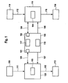
- FIG. 1 shows schematically a system with at least two processors which access a storage means. Based on the waveform of the processors and a comparison means to the program processing in at least To prevent a processor, the inventive concept is explained in Figure 2.
- FIG. 1 shows a system for controlling processes in a vehicle.
- 119 represents a first subsystem, in particular a control unit 119 with a processor 104, in particular a CPU.
- a processor 104 in particular a CPU.
- measured or otherwise determined operating variables from an element 110 which corresponds to a measuring device, a further control unit, etc. supplied via interface 112 to the subsystem 119.
- These signals which are transmitted via the interface 112 thus correspond to measured operating variables or can be derived from these signals such operating variables.
- the processor unit 104 forms in the context of programs or control functions implemented in at least one memory in the form of program code, values for the control variables to be output, which control elements, in particular represented by element 114, in FIG Setting the sense of a given control strategy.
- the processes to be controlled in this case are part of a transmission control, control of the chassis (ABS, ASR, ESP, etc.), in particular the brake, control of comfort and safety electronics, control of a drive unit, in particular an internal combustion engine, control of the drive train, or other Control operations included in the vehicle.
- Subsystem 119 as well as subsystem 120 are preferably a control unit for controlling a drive unit, in particular an internal combustion engine of a vehicle.
- a control unit for controlling a drive unit, in particular an internal combustion engine of a vehicle.
- signals which measured Operating variables of the drive unit, the drive train and / or the vehicle correspond or from which such operating variables can be derived from the elements 109 and 110, in particular measuring elements or other control units via the interface 111 and 112, the subsystems 119 and 120 supplied.
- these subsystems can correspond only to the processor units or processors 103 and 104 or contain further elements such as, for example, memory elements, in particular a program memory, further interfaces or the like.
- the processors 103 and 104 or the subsystems 119 and 120 can be housed in a control unit as well as they can be distributed to different control devices.
- the signal or the operating variables supplied by the elements 109 and 110 are, in particular, those operating variables which can be evaluated for controlling a drive unit, in particular an internal combustion engine. Signals are also output via the interfaces 115 and 116, which actuate actuating elements or actuators for setting at least one operating variable of the vehicle, in particular a drive unit.
- the respective processor unit 104 or 103 thus forms the control variables for the actuating elements 113 and 114, respectively, in accordance with a control strategy.
- the position of a driver-actuated position is known Operating element detected, evaluated and determined a target value for a torque of the drive unit.
- setpoint values received via the interfaces 111 and 112 for example, of other control systems, such as a traction control, a transmission control, etc. as well as internally formed setpoints (limits, etc.) for determining a setpoint, eg for the torque.
- This is then converted in a preferred embodiment of an internal combustion engine control into a desired value for the position of the throttle valve, which is set as part of a bearing control loop.
- further power-determining functions are provided, for example, control of a turbocharger, exhaust gas recirculation, an idle speed control, etc.
- the programs required for this purpose can be accommodated once in program memories contained in the subsystems 119 and 120, respectively, or in a central memory 100.
- data can be stored either in the subsystems themselves, ie in 119 or 120 in memory elements or in a common memory Memory element 100. If programs and / or data are stored in a central memory element 100, both subsystems or in particular processors 103 or 104 access this central memory element 100. This is done via the ports 101 and 102 by means of the interfaces 105 and 106. Via the interfaces 105 or 106 is thus written by the processors 103 and 104 in memory element 100 and read from these.
- the bidirectional transmission of information can be done serially as well as in parallel.
- the parallel transmission of the information has the advantage that the address is very quickly available for an address comparison.
- the memory element 100 can be a dual-port RAM for coupling between the processors or, for example, can also be designed as a conventional, ie single-port RAM with an upstream multiplexer. In principle, however, any volatile or nonvolatile memory can be used.
- the memory element 100 contains an address comparator 117.
- the address comparator circuit 117 serves to detect the case when the two processors 103 and 104 access the same address. In this case, the two addresses are compared via port 101 or 102, for example via a comparator arrangement, and depending on the result of the comparison, signals are transmitted to the processors 103 and 104, respectively. These signals are transmitted via interfaces 107 and 108, respectively. In the simplest case, a stop signal is transmitted to the processor to be stopped via the interface 107 or 108.
- Element 118 serves to carry out the coordination, which processor is to be stopped, that is to which processor to which signal is to be transmitted.
- These Coordination circuit 118 is meaningfully also accommodated in the memory element 100 or together with it in a component.
- it is determined via the address comparison in the address comparator 117 that the two processors 103 and 104 want to access an identical address.
- the access does not have to be absolutely simultaneous.
- Equality in this case also means within a certain, predeterminable time window.
- Several variants are possible. Once, it is possible to wait for the data to be sent following the address transfer until the address of the second processor is completely compared with the first one. However, this has the disadvantage that it creates waiting times.
- Another possibility is to determine when creating an address only whether the other processor also plans an access. If an address is already present through the respective other processor, then the address is first compared before the second one is allowed to begin access. If there is no further address of the other processor at the time of the address transmission, the read access of the first accessing processor is automatically started after transmission of the complete address. These checks are performed in the comparison circuit 117.
- a DPRAM can then be used for coupling between the microprocessors, the signals of the DPRAM then being routed to the processors without additional hardware and being used to automatically trigger the impending conflict in quasi-simultaneous access to the same DPRAM memory cell to decouple in time.
- at least one processor is temporarily halted or the program execution is inhibited by this processor.
- a simple signal is output by the coordination circuit 118.
- the addresses, chip enable signals, output enable signals, read and write signals of the two ports 101 and 102, individually or in combination in the Coordination logic 118 are used to form the signals via interfaces 107 and 108.
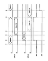
- processor 103 starts, in this case CPU1, with the transmission of the access address.
- a signal A1 is transmitted via interface 105 and port 101 to memory element 100.
- processor 104 here referred to as CPU2
- the associated signal is referred to here as A2.
- the comparison circuit 117 is thus determined at the time t2 that at the same time two addresses, possibly the same addresses are accessed.
- a signal AV2 is thus initiated at the time t2.
- the processor 103 Since no further address was applied at the time t1, the processor 103, that is to say CPU1, starts the write / read access (S / L) of the above address at the time t3 following the complete transmission of the address, that is to say the signal A1.
- a second signal AV1 is formed which is intended for the respective other processor.
- processor 104 ie CPU2 has the address Signal A2 completely transferred and would start with the read / write access, ie signal D2 to memory element 100. If it is determined in the address comparator 117 that the two addresses are thus equal to the signals A1 and A2, the signal AV2 is output by the coordination circuit 118 to the CPU2, that is, the processor 104. This prevents access to the memory location.
- AV1 is output via interface 108 at the processor 103, ie CPU1, which allows further access.
- CPU1 wants to access the same address again. However, since CPU2 is currently in the access S / L to this address, the signal AV1 is set and output to CPU1, ie processor 103 via line 107 by the coordination circuit 118. As a result, the access by processor 103, so CPU1 is in turn prevented.
- the advantage of the invention is in particular that both subsystems 119 and 120 or the processors 104 and 103 asynchronously and thus virtually work with full performance and can exchange information.
- a storage device with more than two simultaneous access possibilities can also be used according to the invention, in particular a quadripole RAM, that is to say a volatile memory with in this case especially four simultaneous access possibilities by e.g. two or four processors.
Description
Die Erfindung betrifft Verfahren und Vorrichtung zur Steuerung von Vorgängen in einem Fahrzeug, wobei wenigstens zwei Prozessoren auf wenigstens ein Speichermittel zugreifen, gemäß den Oberbegriffen der unabhängigen Ansprüche.The invention relates to methods and apparatus for controlling operations in a vehicle, wherein at least two processors access at least one storage means, according to the preambles of the independent claims.
Dazu zeigt die DE 41 29 809 A1 ein Mehrrechnersystem, insbesondere zur Steuerung von Vorgängen in Kraftfahrzeugen. Dabei greifen wenigstens zwei Rechner gemeinsam auf ein Speichermittel zu. Um bei mehreren Rechnern die Sicherheit der Datenübertragung bei Zugriff auf den gleichen Speicher zu gewährleisten und Verzögerungen durch den Datenaustausch zwischen den Rechnern zu minimieren, wird das Speichermittel in wenigstens zwei Bereiche unterteilt. Auf den ersten Speicherbereich greift ein erster Rechner nur lesend und ein zweiter Rechner nur schreibend zu. Auf den zweiten Speicherbereich greift der zweite Rechner nur lesend und der erste Rechner nur schreibend zu. Dabei sind die Rechner so synchronisiert, daß sie zum gleichen Zeitpunkt in der gleichen Weise auf das Speichermittel zugreifen. Da nun beide Rechner entweder lesend oder schreibend auf entkoppelte Speicherbereiche zugreifen, wird eine Kollision, also ein Lese- bzw. Schreibzugriff auf die gleiche Adresse in dem Speichermittel verhindert. Durch diese Synchronisation kann es allerdings zu unerwünschten Wartezeiten in der Programmabarbeitung kommen.For this purpose, DE 41 29 809 A1 shows a multi-computer system, in particular for controlling processes in motor vehicles. In this case, at least two computers access together to a storage means. In order to ensure the security of the data transfer in accessing the same memory in multiple computers and to minimize delays due to the exchange of data between the computers, the storage means is divided into at least two areas. On the first memory area accesses a first computer read only and a second computer only write. On the second memory area of the second computer accesses only reading and the first computer only write. The computers are synchronized so that they access the storage means in the same way at the same time. Since both computers either read or write on access decoupled memory areas, a collision, so a read or write access to the same address in the storage means is prevented. However, this synchronization can lead to unwanted waiting times in program execution.
So zeigt sich, daß der Stand der Technik nicht in jeder Hinsicht optimale Ergebnisse zu liefern vermag.Thus, it can be seen that the prior art can not provide optimal results in every respect.
Damit stellt sich die Aufgage bei wenigstens zwei, insbesondere unabhängig voneinander arbeitenden Prozessoren, welche auf ein Speichermittel zugreifen, asynchronen Datentransfer und möglichst hohen Datendurchsatz zu erzielen und die Erkennung und Vermeidung von Kollisionen bei gleichzeitigem Lese- und/oder Schreibzugriff zu optimieren.This raises the cost of at least two, in particular independently operating processors which access a memory means to achieve asynchronous data transfer and the highest possible data throughput and to optimize the detection and avoidance of collisions with simultaneous read and / or write access.
Die Erfindung geht von einem Verfahren und einer Vorrichtung zur Steuerung von Vorgängen in einem Fahrzeug aus, wobei wenigstens zwei Prozessoren auf wenigstens ein Speichermittel zugreifen und ein gleichzeitiger Lese- und/oder Schreibzugriff bei wenigstens zwei Prozessoren auf die gleiche Adresse des Speichermittels in einer Programmabarbeitung verhindert wird. Vorteilhafterweise wird vor dem eigentlichen Lese- und/oder Schreibzugriff durch einen Adreßvergleich erkannt, daß die wenigstens zwei Prozessoren auf die gleiche Adresse zugreifen werden.The invention is based on a method and a device for controlling operations in a vehicle, wherein at least two processors access at least one memory means and prevent a simultaneous read and / or write access at least two processors to the same address of the memory means in a program execution becomes. Advantageously, it is recognized by an address comparison before the actual read and / or write access that the at least two processors will access the same address.
Zweckmäßigerweise wird abhängig von dem Adreßvergleich ein erstes Signal an den ersten Prozessor und ein zweites Signal an einen zweiten Prozessor übermittelt und die Programmabarbeitung wenigstens eines der wenigstens zwei Prozessoren durch das jeweilige Signal unterbunden.Expediently, depending on the address comparison, a first signal is transmitted to the first processor and a second signal is transmitted to a second processor and the program execution of at least one of the at least two processors is prevented by the respective signal.
Vorteilhafterweise wird dadurch, daß die Programmabarbeitung des wenigstens ersten der wenigstens zwei Rechner durch das jeweilige Signal solange unterbunden wird, bis im Adreßvergleich wieder verschiedene Adressen erkannt werden und/oder der Lese- und/oder Schreibzugriff des wenigstens zweiten Prozessors beendet ist, der Zugriff der wenigstens zwei Prozessoren auf das wenigstens eine Speichermittel zeitlich entkoppelt.Advantageously, the program execution of the at least first of the at least two computers is inhibited by the respective signal until different addresses are again detected in the address comparison and / or the read and / or write access of the at least second processor is terminated, the access of at least two processors temporally decoupled to the at least one storage means.
In einer vorteilhaften Ausgestaltung wird die Programmabarbeitung wenigstens eines der wenigstens zwei Prozessoren durch das jeweilige Signal für eine vorgebbare und/oder aus dem Adreßvergleich ermittelbare Zeit unterbunden.In an advantageous embodiment, the program execution of at least one of the at least two processors is prevented by the respective signal for a predeterminable and / or time determinable from the address comparison.
Weiterhin von Vorteil ist, daß die Lese- und/oder Schreibzugriffe der wenigstens zwei Prozessoren auf Adressen des wenigstens einen Speichermittels asynchron, also zu beliebigen Zeitpunkten erfolgen können.It is furthermore advantageous that the read and / or write accesses of the at least two processors to addresses of the at least one memory means can be carried out asynchronously, ie at arbitrary times.
Dabei dient zweckmäßigerweise als Kriterium bei gleichzeitigem oder nahezu gleichzeitigen Zugriff auf die gleiche Adresse um festzustellen welcher Prozessor in seiner Programmabarbeitung unterbunden werden soll, die Tatsache welcher Prozessor zuerst den Zugriff gestartet hat bzw. durch welchen Prozessor die Adresse zuerst übermittelt wurde.It serves expediently as a criterion for simultaneous or almost simultaneous access to the same address to determine which processor is to be inhibited in its program execution, the fact which processor has first started the access or by which processor the address was first transmitted.
Dadurch wird vorteilhafter Weise vermieden, daß der gelesene Inhalt unter einer Adresse ungültig ist.This advantageously avoids that the read content is invalid under an address.
Damit ergibt sich ein Kostenvorteil einmal gegenüber dem Einsatz synchroner Speichermittel bzw. eine den Zugriff synchronisierenden Einrichtung und zum anderen gegenüber dem Einsatz aufwendiger Hardwareschaltungen, wie z.B. zusätzlicher Register (Hardware-Semaphores) zur Kollisionsvermeidung.This results in a cost advantage once compared to the use of synchronous storage means or a device synchronizing the access and on the other hand against the use of expensive hardware circuits, such as additional register (hardware semaphore) for collision avoidance.
Dadurch, daß beide Teilsysteme, insbesondere beide Prozessoren asynchron also mit voller Perfomance arbeiten und Informationen austauschen, können höhere Datendurchsätze erzielt werden. Die Prozessoren arbeiten unabhängig und greifen zu beliebigen Zeitpunkten auf das gemeinsame Speichermittel zu. Selbstverständlich kann die Erfindung auch in einem synchronisierten Betrieb der wenigstens zwei Prozessoren Verwendung finden.The fact that both subsystems, in particular both processors work asynchronously so with full performance and exchange information, higher data throughputs can be achieved. The processors work independently and access the common storage means at arbitrary times. Of course, the invention can also be used in a synchronized operation of the at least two processors.
Ebenso wird zweckmäßiger Weise eine zusätzliche Interrupt- bzw. Interuptbearbeitungsbelastung in Folge einer Rechnerkopplung, also einer Kopplung beider Prozessoren vermieden.Likewise expediently an additional interrupt or interrupt processing load as a result of a computer coupling, ie a coupling of both processors is avoided.
Vorteilhafterweise ist die Mehrbelastung für die Laufzeit sehr gering, da nur im drohenden Konfliktfall eine zeitliche Zugriffsentkopplung erfolgt, was aber selten vorkommt. Dadurch wird die höchstmögliche Aktualität der Daten im Speicher gewährleistet.Advantageously, the additional burden for the duration is very low, since only in the impending conflict, a temporal access decoupling occurs, but rarely occurs. This ensures the highest possible up-to-dateness of the data in the memory.
Weitere Vorteile und vorteilhafte Ausgestaltungen ergeben sich aus der Beschreibung und den Ansprüchen.Further advantages and advantageous embodiments will become apparent from the description and the claims.
Die Erfindung wird im weiteren anhand der in der Zeichnung dargestellten Figuren näher erläutert.
Figur 1 zeigt dabei schematisch ein System mit wenigstens zwei Prozessoren, die auf ein Speichermittel zugreifen. Anhand des Signalverlaufs der Prozessoren und eines Vergleichsmittels um die Programmabarbeitung in wenigstens einem Prozessor zu unterbinden, wird der erfindungsgemäße Gedanke in Figur 2 erläutert.The invention will be explained in more detail with reference to the figures shown in the drawing.
FIG. 1 shows schematically a system with at least two processors which access a storage means. Based on the waveform of the processors and a comparison means to the program processing in at least To prevent a processor, the inventive concept is explained in Figure 2.
Figur 1 zeigt ein System zur Steuerung von Vorgängen bzw. Prozessen in einem Fahrzeug. Mit 119 ist dabei ein erstes Teilsystem, insbesondere eine Steuereinheit 119 mit einem Prozessor 104, insbesondere einer CPU dargestellt. Dabei werden gemessene oder anderweitig ermittelte Betriebsgrößen aus einem Element 110, welches einer Meßeinrichtung, einer weiteren Steuereinheit, usw. entspricht über Schnittstelle 112 dem Teilsystem 119 zugeführt. Diese Signale die über die Schnittstelle 112 übertragen werden, entsprechen somit gemessenen Betriebsgrößen bzw. können aus diesen Signalen solche Betriebsgrößen abgeleitet werden. In Abhängigkeit der Eingangssignale, daraus abgeleiteter Betriebsgrößen und/oder interner Größen bildet die Prozessoreinheit 104 im Rahmen der in wenigstens einem Speicher implementierten Programme bzw. Steuerfunktionen in Form vom Programmcode, Werte für die auszugebenden Steuergrößen, welche Stellelemente, insbesondere dargestellt durch Element 114, im Sinne einer vorgegebenen Steuer- bzw. Regelstrategie einstellen. Die dabei zu steuernden Vorgänge sind dabei beispielsweise Teil einer Getriebesteuerung, Steuerung des Fahrwerks (ABS, ASR, ESP usw.), insbesondere der Bremse, Steuerung von Komfort- und Sicherheitselektronik, Steuerung einer Antriebseinheit, insbesondere einer Brennkraftmaschine, Steuerung des Triebstrangs, oder sonstige im Fahrzeug enthaltene Steuervorgänge.FIG. 1 shows a system for controlling processes in a vehicle. 119 represents a first subsystem, in particular a
Bei Teilsystem 119 ebenso wie Teilsystem 120 handelt es sich bevorzugterweise um eine Steuereinheit zur Steuerung einer Antriebseinheit, insbesondere einer Brennkraftmaschine eines Fahrzeugs. Dabei werden nun Signale welche gemessenen Betriebsgrößen der Antriebseinheit, des Triebstrangs und/oder des Fahrzeugs entsprechen oder aus welchen solche Betriebsgrößen abgeleitet werden können, aus den Elementen 109 und 110, insbesondere Meßelementen oder weiteren Steuereinheiten über die Schnittstelle 111 bzw. 112 den Teilsystemen 119 und 120 zugeführt.
Diese Teilsysteme können einerseits lediglich den Prozessoreinheiten bzw. Prozessoren 103 und 104 entsprechen oder weitere Elemente wie beispielsweise Speicherelemente, insbesondere einen Programmspeicher, weitere Schnittstellen oder ähnliches enthalten. Die Prozessoren 103 und 104 bzw. die Teilsysteme 119 und 120 können dabei in einem Steuergerät ebenso untergerbracht sein, wie sie auf verschieden Steuergeräte verteilt sein können.On the one hand, these subsystems can correspond only to the processor units or
Die durch die Elemente 109 und 110 zugeführten Signal bzw. die Betriebsgrößen sind insbesondere solche Betriebsgrößen, die zur Steuerung einer Antriebseinheit, insbesondere einer Brennkraftmaschine ausgewertet werden können. Über die Schnittstellen 115 bzw. 116 werden ferner Signale ausgegeben, welche Stellelemente bzw. Aktuatoren zur Einstellung wenigstens einer Betriebsgröße des Fahrzeugs, insbesondere einer Antriebseinheit betätigen. In Abhängigkeit der Eingangssignale, daraus abgeleiteter Betriebsgrößen und/oder interner Größen bildet die jeweilige Prozessoreinheit 104 bzw. 103 somit gemäß einer Steuer- bzw. Regelstrategie die Steuergrößen für die Stellelemente 113 bzw. 114. Beispielsweise wird in bekannter Weise die Stellung eines vom Fahrer betätigbaren Bedienelementes erfaßt, ausgewertet und ein Sollwert für ein Drehmoment der Antriebseinheit ermittelt. Dies führt dann unter Berücksichtigung der über die Schnittstellen 111 bzw. 112 empfangenen Sollwerte beispielsweise anderer Steuersysteme, wie einer Antriebsschlupfregelung, einer Getriebesteuerung, usw. sowie intern gebildeter Sollwerte (Begrenzungen etc.) zur Ermittlung eines Sollwertes z.B. für das Drehmoment. Dieses wird dann in bevorzugten Ausführungsbeispiel einer Brennkraftmaschinensteuerung in einen Sollwert für die Stellung der Drosselklappe, der im Rahmen eines Lagerregelkreises eingestellt wird, umgewandelt. Ferner sind je nach Ausstattung der Brennkraftmaschine weitere leistungsbestimmende Funktionen vorgesehen, beispielsweise Steuerung eines Turboladers, einer Abgasrückführung, einer Lehrlaufdrehzahlregelung, usw.The signal or the operating variables supplied by the
Darüber hinaus sind bei Brennkraftmaschine mit Benzindirekteinspritzung nicht nur die Lufteinstellung sondern auch die Bestimmung der einzuspritzenden Kraftstoffmasse, die Bestimmung eines einzustellenden Luft/Kraftstoffverhältnisses, die Vorgabe des Einspritzverlaufes (Voreinspritzung, Nacheinspritzung), die Steuerung einer Ladungsbewegungsklappe, usw. leistungsbestimmend, so daß dort neben den geschilderten eine Vielzahl weiterer Programme bzw. Steuerfunktionen vorzusehen sind, die Einfluß auf die Leistung der Brennkraftmaschinen somit auf die Sicherheit des Fahrzeugs haben.In addition, in internal combustion engine with gasoline direct injection, not only the air setting but also the determination of the fuel mass to be injected, the determination of an air / fuel ratio to be set, the specification of the injection curve (pilot injection, post injection), the control of a charge movement flap, etc. performance determining, so that there next the described a variety of other programs or control functions are provided, the influence on the performance of the internal combustion engine thus have on the safety of the vehicle.
Die dazu benötigten Programme können einmal in, in den Teilsystemen 119 bzw. 120 enthaltenen Programmspeichern untergebracht sein, oder in einem zentralen Speicher 100. Ebenso können Daten entweder in den Teilsystemen selbst, also in 119 bzw. 120 in Speicherelementen abgelegt sein oder in einem gemeinsamen Speicherelement 100. Sind Programme und/oder Daten in einem zentralen Speicherelement 100 abgelegt, so greifen beide Teilsysteme bzw. insbesondere Prozessoren 103 bzw. 104 auf dieses zentrale Speicherelement 100 zu. Dies geschieht über die Ports 101 und 102 mittels der Schnittstellen 105 und 106. Über die Schnittstellen 105 bzw. 106 wird somit durch die Prozessoren 103 und 104 in Speicherelement 100 geschrieben sowie aus diesen ausgelesen. Die bidirektionale Übertragung der Information kann dabei seriell ebenso wie parallel erfolgen. Die parallele Übertragung der Information hat dabei den Vorteil, daß für einen Adreßvergleich die jeweilige Adresse sehr schnell zur Verfügung steht.The programs required for this purpose can be accommodated once in program memories contained in the
Das Speicherelement 100 kann dabei ein Dual-Port-RAM zur Kopplung zwischen den Prozessoren sein oder auch beispielsweise als ein übliches, also Single-Port-RAM mit einem vorgeschalteten Multiplexer ausgebildet sein. Prinzipiell können aber beliebige flüchtige oder nichtflüchtige Speicher dabei Verwendung finden.In this case, the
Bei einem normalen flüchtigen Speicher, wenn dann also jeder Prozessor z.B. in der Hälfte der Zeit zugreifen kann, teilen sich beide den Speicher ohne Zugriffsprobleme. Dies bedeutet allerdings Einschränkungen in der Performance.In a normal volatile memory, so if each processor, e.g. can access in half the time, both share memory without access problems. However, this means limitations in performance.
Im Speicherelement 100 ist ein Adreßvergleicher 117 enthalten. Die Adreßvergleicherschaltung 117 dient dabei zur Erkennung des Falles, wenn die beiden Prozessoren 103 und 104 auf die gleiche Adresse zugreifen. Dabei werden die beiden Adressen über Port 101 bzw. 102 beispielsweise über eine Komperatoranordnung verglichen und abhängig vom Ergebnis des Vergleiches Signale an die Prozessoren 103 bzw. 104 übermittelt. Diese Signale werden über Schnittstellen 107 bzw. 108 übertragen. Im einfachsten Fall wird über die Schnittstelle 107 bzw. 108 ein Stopsignal an den anzuhaltenden Prozessor übertragen.The
Element 118 dient dabei dazu, die Koordination durchzuführen, welcher Prozessor anzuhalten ist, also an welchen Prozessor welches Signal zu übertragen ist. Diese Koordinationsschaltung 118 ist dabei sinnvoller Weise ebenfalls im Speicherelement 100 bzw. mit diesem zusammen in einem Bauteil untergebracht. Somit wird im einfachsten Fall über den Adreßvergleich im Adreßvergleicher 117 festgestellt, daß die beiden Prozessoren 103 und 104 auf eine identische Adresse zugreifen wollen. Der Zugriff muß dabei nicht absolut zeitgleich erfolgen. Zeitgleichheit bedeutet in diesem Fall auch innerhalb eines bestimmten, vorgebbaren Zeitfensters. Dabei sind mehrere Varianten möglich. Einmal kann mit dem Senden der Daten im Anschluß an die Adreßübertragung solange gewartet werden, bis die Adresse des zweiten Prozessors vollständig mit der ersten verglichen ist. Dies hat allerdings den Nachteil, daß dabei Wartezeiten entstehen. Eine weitere Möglichkeit ist, bei Anlegen einer Adresse lediglich festzustellen, ob der jeweils andere Prozessor ebenfalls einen Zugriff plant. Liegt bereits eine Adresse durch den jeweils anderen Prozessor an, wird dann zunächst die Adresse verglichen, bevor der zweite mit dem Zugriff beginnen darf. Liegt bei Adreßsendung keine weitere Adresse des jeweils anderen Prozessors vor, wird automatisch nach Übertragung der vollständigen Adresse mit dem Schreib- /Lesezugriff des zuerst zugreifenden Prozessors begonnen. Diese Überprüfungen werden in der Vergleichsschaltung 117 durchgeführt.
In einem Beispiel kann somit mit Speicherelement 100 ein DPRAM zur Kopplung zwischen den Mikroprozessoren eingesetzt werden, wobei die Signale des DPRAMS dann ohne Zusatzhardware zu den Prozessoren geführt werden und dazu verwendet werden, den drohenden Konfliktfall den quasi gleichzeitigen Zugriff auf die gleiche DPRAM-Speicherzelle automatisch zeitlich zu entkoppeln. Dabei wird wenigstens ein Prozessor vorläufig angehalten bzw. die Programmabarbeitung durch diesen Prozessor unterbunden.In one example, with
Damit erfolgt im Prinzip der schreibende und lesende Zugriff auf Daten in dem DPRAM in dem Mikroprozessor an beliebiger Stelle im Programmablauf ohne jede Einschränkung oder Zusatzmaßnahme in der Software.Thus, in principle, the writing and reading access to data in the DPRAM in the microprocessor at any point in the program flow without any restriction or additional measure in the software.
Im einfachsten Fall wird durch die Koordinationsschaltung 118 ein einfaches Signal ausgegeben. Für die Bildung der Signale insbesondere in Form von Flags oder längeren Botschaften können je nach Ausführung die Adressen, Chip-Enable-Signale, Output-Enable-Signale, Read- und Write-Signale der beiden Ports 101 und 102 einzeln oder in Kombination in der Koordinationslogik 118 zur Bildung der Signale über Schnittstellen 107 und 108 herangezogen werden.In the simplest case, a simple signal is output by the
Der erfindungsgemäße Gedanke ist an einem Beispiel in Figur 2 in Form eines Signalflußplans nochmals dargestellt. Zum Zeitpunkt t1 beginnt Prozessor 103, also hier CPU1 mit der Übertragung der Zugriffsadresse. Es wird also ein Signal A1 über Schnittstelle 105 und Port 101 zu Speicherelement 100 übertragen. Zum Zeitpunkt t2 beginnt Prozessor 104 hier als CPU2 bezeichnet mit der Übertragung einer Adresse für einen Schreib- /Lesezugriff. Das zugehörige Signal wird hier mit A2 bezeichnet. In der Vergleichsschaltung 117 wird damit zum Zeitpunkt t2 festgestellt, daß gleichzeitig auf zwei Adressen, möglicherweise gleiche Adressen zugegriffen wird. Im Adreßvergleicher wird somit zum Zeitpunkt t2 ein Signal AV2 initiiert.The idea according to the invention is shown once more in an example in FIG. 2 in the form of a signal flow diagram. At time t1,
Da zum Zeitpunkt t1 keine weitere Adresse anlag, wird zum Zeitpunkt t3 durch Prozessor 103, also CPU1 im Anschluß an die vollständige Übertragung der Adresse, also Signal A1 mit dem Schreib-/Lesezugriff (S/L) obiger Adresse begonnen. Gleichzeitig wird ein zweites Signal AV1 gebildet, welches für den jeweils anderen Prozessor bestimmt ist. Zum Zeitpunkt t4 hat Prozessor 104, also CPU2 die Adresse also Signal A2 vollständig übertragen und würde mit dem Schreib-/Lesezugriff, also Signal D2 auf Speicherelement 100 beginnen. Wird im Adreßvergleicher 117 festgestellt, daß die beiden Adressen also Signal A1 und A2 gleich sind, wird Signal AV2 durch die Koordinierungsschaltung 118 auf CPU2 also Prozessor 104 ausgegeben. Dadurch wird der Zugriff auf die Speicherstelle unterbunden. Gleichzeitig wird AV1 über Schnittstelle 108 beim Prozessor 103, also CPU1 ausgegeben, was den weiteren Zugriff ermöglicht.Since no further address was applied at the time t1, the
Zum Zeitpunkt t5 ist der Zugriff durch CPU1 also Prozessor 103 beendet. Bis zu diesem Zeitpunkt t5 liegt die gewünschte Adresse, also Signal A1 vor. Ebenso wird die Adresse der CPU2, also Prozessor 104 weiterhin aufrechterhalten. Zum Zeitpunkt t5 ergibt der Adreßvergleich somit das nicht mehr die gleichen Adressen bezüglich des Zugriffs anliegen bzw. der Zugriff durch CPU1, Prozessor 103 beendet ist. Das Signal AV2 für CPU2 fällt damit ab. Somit wird zum Zeitpunkt t5 mit dem Zugriff S/L, also Signal D2 auf die gewünschte Adresse begonnen.At time t5, access by CPU1,
Zum Zeitpunkt t6 will CPU1 beispielsweise wieder auf die gleiche Adresse zugreifen. Da aber nun CPU2 sich gerade im Zugriff S/L auf diese Adresse befindet, wird das Signal AV1 gesetzt und an CPU1 sprich Prozessor 103 über Leitung 107 durch die Koordinationsschaltung 118 ausgegeben. Dadurch wird der Zugriff durch Prozessor 103, also CPU1 seinerseits unterbunden.At time t6, for example, CPU1 wants to access the same address again. However, since CPU2 is currently in the access S / L to this address, the signal AV1 is set and output to CPU1,
Statt der Übertragung zweier Signale AV2 und AV1 bzw. daraus abgeleiteter Informationen an die beiden Prozessoren könnte auch nur ein als Stoppsignal interpretierbares Signal AV gebildet werden, welches je nachdem durch Koordinationsschaltung 118 dem einen oder anderen Prozessor zugeleitet wird. Durch dieses Signal wird der jeweilige Prozessor, insbesondere der, der zu spät, bei zwei Prozessoren also als zweites auf die gleiche Adresse zugreift, gestoppt bzw. die Programmabarbeitung solange unterbunden, bis die Zugriffskollision nicht mehr auftritt.Instead of transmitting two signals AV2 and AV1 or information derived therefrom to the two processors, it would also be possible to form only one signal AV which can be interpreted as a stop signal, which signal is fed to the one or the other processor by
Somit ist der Vorteil der Erfindung insbesondere, daß beide Teilsysteme 119 und 120 bzw. die Prozessoren 104 und 103 asynchron und damit quasi mit voller Performance arbeiten und Informationen austauschen können. Es gibt nur dann eine Rückwirkung von einem Teilsystem auf das andere, wenn beide gleichzeitig die gleiche Zelle im Speicherelement, insbesondere in einem Dual-Port-RAM, ansprechen wollen und damit ein Prozessor kurz angehalten wird, um die Kollision zu vermeiden. Da dies nur selten vorkommt, ist die Performance Einschränkung durch das Verfahren und die Vorrichtung zu vernachlässigen.Thus, the advantage of the invention is in particular that both
Statt eines DPRAMs ist auch ein Speichermittel mit mehr als zwei gleichzeitigen Zugriffsmöglichkeiten erfindungsgemäß einsetzbar, insbesondere ein Quadropol-RAM, also ein flüchtiger Speicher mit hier speziell vier gleichzeitigen Zugriffsmöglichkeiten durch z.B. zwei oder vier Prozessoren.Instead of a DPRAM, a storage device with more than two simultaneous access possibilities can also be used according to the invention, in particular a quadripole RAM, that is to say a volatile memory with in this case especially four simultaneous access possibilities by e.g. two or four processors.
Claims (7)
- Method for controlling processes in a vehicle, at least two processors (103, 104) accessing at least one storage means and a simultaneous reading and/or writing access by the at least two processors to the same address of the storage means in a program processing operation being prevented, characterized in that the same address is recognized by an address comparison and at least one signal is transmitted to at least one processor as a function of the address comparison and the program processing operation of the at least one processor is prohibited by the signal.
- Method according to Claim 1, characterized in that a first signal is transmitted to a first processor, and a second signal is transmitted to a second processor, and the program processing operation of at least one processor is prohibited by the signal.
- Method according to Claim 1, characterized in that the program processing of the at least one of the at least two processors is prohibited by the respective signal until various addresses in the address comparison are recognized again and/or the reading and/or writing access of the at least second processor is ended.
- Method according to Claim 1, characterized in that the program processing operation by at least one of the at least two processors is prohibited by the respective signal for a predefinable time and/or a time which can be determined from the address comparison.
- Method according to Claim 1, characterized in that the reading and/or writing access to addresses of the storage means in a program processing operation of at least two processors are asynchronous, that is to say take place at any times.
- Method according to Claims 1 and 2, characterized in that the program processing operation of the at least second processor is prohibited if the reading and/or writing access by the first processor to the same address has been detected simultaneously before the reading and/or writing access of the second processor by reference to the address comparison.
- Device for controlling processes in a vehicle, having at least two processors (103, 104) and at least one storage means (100), the at least two processors accessing the at least one storage means and a simultaneous reading and/or writing access by the at least two processors to the same address of the storage means in a program processing operation being prevented, characterized in that the device contains first means (117) which recognize the same address by an address comparison, and contains second means (118) which, as a function of the address comparison, transmit a first signal to the first processor and a second signal to the second processor and prohibit the program processing operation of at least one of the at least two processors by means of the respective signal.
Applications Claiming Priority (2)
| Application Number | Priority Date | Filing Date | Title |
|---|---|---|---|
| DE19949051A DE19949051A1 (en) | 1999-10-11 | 1999-10-11 | Method and device for controlling processes in a vehicle |
| DE19949051 | 1999-10-11 |
Publications (3)
| Publication Number | Publication Date |
|---|---|
| EP1093037A2 EP1093037A2 (en) | 2001-04-18 |
| EP1093037A3 EP1093037A3 (en) | 2004-01-21 |
| EP1093037B1 true EP1093037B1 (en) | 2006-08-30 |
Family
ID=7925303
Family Applications (1)
| Application Number | Title | Priority Date | Filing Date |
|---|---|---|---|
| EP00120965A Expired - Lifetime EP1093037B1 (en) | 1999-10-11 | 2000-09-27 | Process and device for the control of processes in a vehicle |
Country Status (4)
| Country | Link |
|---|---|
| US (1) | US6356813B1 (en) |
| EP (1) | EP1093037B1 (en) |
| JP (1) | JP2001166982A (en) |
| DE (2) | DE19949051A1 (en) |
Families Citing this family (14)
| Publication number | Priority date | Publication date | Assignee | Title |
|---|---|---|---|---|
| DE10113917B4 (en) * | 2001-03-21 | 2019-05-23 | Robert Bosch Gmbh | Method and device for monitoring control units |
| JP4785320B2 (en) * | 2002-01-31 | 2011-10-05 | キヤノン株式会社 | Storage device |
| US7983820B2 (en) * | 2003-07-02 | 2011-07-19 | Caterpillar Inc. | Systems and methods for providing proxy control functions in a work machine |
| US20050002354A1 (en) * | 2003-07-02 | 2005-01-06 | Kelly Thomas J. | Systems and methods for providing network communications between work machines |
| US7516244B2 (en) * | 2003-07-02 | 2009-04-07 | Caterpillar Inc. | Systems and methods for providing server operations in a work machine |
| US20050005167A1 (en) * | 2003-07-02 | 2005-01-06 | Kelly Thomas J. | Systems and methods for providing security operations in a work machine |
| JP4089620B2 (en) * | 2004-01-15 | 2008-05-28 | 株式会社デンソー | Vehicle control system |
| DE102005048581B4 (en) * | 2005-10-06 | 2022-06-09 | Robert Bosch Gmbh | Subscriber interface between a FlexRay communication module and a FlexRay subscriber and method for transmitting messages via such an interface |
| DE102006002824B4 (en) * | 2006-01-19 | 2008-10-09 | Phoenix Contact Gmbh & Co. Kg | Method and device for converting multichannel messages into a single-channel secure message |
| DE102007046731B4 (en) * | 2007-09-28 | 2011-06-09 | Bayerische Motoren Werke Aktiengesellschaft | Method for controlling an actuator in a motor vehicle |
| DE102008030092A1 (en) * | 2008-06-25 | 2009-12-31 | Audi Ag | Electrically controllable assembly of a motor vehicle and method for identifying an electrically controllable assembly of a motor vehicle |
| DE102010044644B4 (en) * | 2010-09-07 | 2018-12-27 | Robert Bosch Gmbh | Method for collision detection for a drive unit |
| DE102010052486B4 (en) * | 2010-11-26 | 2015-08-27 | Bombardier Transportation Gmbh | Control arrangement for controlling the operation of a track-bound vehicle and method for producing the control arrangement |
| US10037016B2 (en) * | 2016-03-23 | 2018-07-31 | GM Global Technology Operations LLC | Hybrid dual-duplex fail-operational pattern and generalization to arbitrary number of failures |
Family Cites Families (6)
| Publication number | Priority date | Publication date | Assignee | Title |
|---|---|---|---|---|
| DE3673578D1 (en) * | 1985-05-09 | 1990-09-27 | Voest Alpine Automotive | MICRO COMPUTER SYSTEM. |
| DE4129809C2 (en) * | 1991-01-28 | 2000-08-17 | Bosch Gmbh Robert | Multi-computer system |
| US6049889A (en) * | 1995-06-07 | 2000-04-11 | Digital Equipment Corporation | High performance recoverable communication method and apparatus for write-only networks |
| US5848367A (en) * | 1996-09-13 | 1998-12-08 | Sony Corporation | System and method for sharing a non-volatile memory element as a boot device |
| US5875472A (en) * | 1997-01-29 | 1999-02-23 | Unisys Corporation | Address conflict detection system employing address indirection for use in a high-speed multi-processor system |
| JP3898264B2 (en) * | 1997-02-21 | 2007-03-28 | 本田技研工業株式会社 | Vehicle network system |
-
1999
- 1999-10-11 DE DE19949051A patent/DE19949051A1/en not_active Ceased
-
2000
- 2000-09-27 EP EP00120965A patent/EP1093037B1/en not_active Expired - Lifetime
- 2000-09-27 DE DE50013381T patent/DE50013381D1/en not_active Expired - Lifetime
- 2000-10-11 JP JP2000310796A patent/JP2001166982A/en active Pending
- 2000-10-11 US US09/686,674 patent/US6356813B1/en not_active Expired - Fee Related
Also Published As
| Publication number | Publication date |
|---|---|
| JP2001166982A (en) | 2001-06-22 |
| DE19949051A1 (en) | 2001-04-12 |
| EP1093037A3 (en) | 2004-01-21 |
| EP1093037A2 (en) | 2001-04-18 |
| DE50013381D1 (en) | 2006-10-12 |
| US6356813B1 (en) | 2002-03-12 |
Similar Documents
| Publication | Publication Date | Title |
|---|---|---|
| EP1093037B1 (en) | Process and device for the control of processes in a vehicle | |
| DE4129809C2 (en) | Multi-computer system | |
| DE4111483C2 (en) | Dual port memory | |
| EP0512240A1 (en) | System for the control of motor vehicles | |
| DE4129287C2 (en) | Electronic control system for a motor vehicle | |
| CH651950A5 (en) | MULTIPROCESSOR ARRANGEMENT. | |
| DE2731188A1 (en) | DATA PROCESSING SYSTEM | |
| DE102006019305A1 (en) | Data transfer from and to engine control unit of motor vehicle, comprises connecting first and second communication interfaces with development tool and functional units respectively, and transferring data from control unit to the tool | |
| EP1222378B1 (en) | Device and method for controlling a drive unit | |
| DE3336977A1 (en) | FAILURE-PROOF METHOD FOR A VEHICLE COMPUTER | |
| DE3501194C2 (en) | Method and device for data exchange between microprocessors | |
| EP0207051B1 (en) | Microcomputer system | |
| DE10252062A1 (en) | In-vehicle electronic controller | |
| EP0209530A1 (en) | Multiprocessor memory access system | |
| WO2007025841A1 (en) | Method for controlling a vehicle drive unit | |
| EP1733284B1 (en) | Control system for operating functions on interacting appliances | |
| WO2009021816A1 (en) | Communication method and interface between a companion chip and a microcontroller | |
| DE19947251A1 (en) | Process and device for controlling processes in connection with a drive | |
| EP0677147B1 (en) | Controller in an arithmetic unit | |
| DE102019120519A1 (en) | Computer-implemented method and computer program product for testing real or virtual control devices | |
| EP0970426B1 (en) | Dependency controller for overlapping memory access operations | |
| EP1137991B1 (en) | Method and device for controlling processes in a vehicle | |
| DE10229520A1 (en) | Controlling vehicle processes, involves copying output parameter of at least one faster task program at start of this program if such an output parameter provided for both faster and slower programs | |
| EP0562151A1 (en) | Integrated microprocessor | |
| DE2612316C3 (en) | Arrangement for controlling the multiplex operation between several channels and a central control circuit of an input / output unit in a data processing system |
Legal Events
| Date | Code | Title | Description |
|---|---|---|---|
| PUAI | Public reference made under article 153(3) epc to a published international application that has entered the european phase |
Free format text: ORIGINAL CODE: 0009012 |
|
| AK | Designated contracting states |
Kind code of ref document: A2 Designated state(s): AT BE CH CY DE DK ES FI FR GB GR IE IT LI LU MC NL PT SE |
|
| AX | Request for extension of the european patent |
Free format text: AL;LT;LV;MK;RO;SI |
|
| PUAL | Search report despatched |
Free format text: ORIGINAL CODE: 0009013 |
|
| AK | Designated contracting states |
Kind code of ref document: A3 Designated state(s): AT BE CH CY DE DK ES FI FR GB GR IE IT LI LU MC NL PT SE |
|
| AX | Request for extension of the european patent |
Extension state: AL LT LV MK RO SI |
|
| 17P | Request for examination filed |
Effective date: 20040721 |
|
| AKX | Designation fees paid |
Designated state(s): DE FR GB |
|
| GRAC | Information related to communication of intention to grant a patent modified |
Free format text: ORIGINAL CODE: EPIDOSCIGR1 |
|
| GRAP | Despatch of communication of intention to grant a patent |
Free format text: ORIGINAL CODE: EPIDOSNIGR1 |
|
| GRAC | Information related to communication of intention to grant a patent modified |
Free format text: ORIGINAL CODE: EPIDOSCIGR1 |
|
| GRAS | Grant fee paid |
Free format text: ORIGINAL CODE: EPIDOSNIGR3 |
|
| GRAA | (expected) grant |
Free format text: ORIGINAL CODE: 0009210 |
|
| AK | Designated contracting states |
Kind code of ref document: B1 Designated state(s): DE FR GB |
|
| REG | Reference to a national code |
Ref country code: GB Ref legal event code: FG4D Free format text: NOT ENGLISH |
|
| REF | Corresponds to: |
Ref document number: 50013381 Country of ref document: DE Date of ref document: 20061012 Kind code of ref document: P |
|
| GBT | Gb: translation of ep patent filed (gb section 77(6)(a)/1977) |
Effective date: 20061128 |
|
| ET | Fr: translation filed | ||
| PLBE | No opposition filed within time limit |
Free format text: ORIGINAL CODE: 0009261 |
|
| STAA | Information on the status of an ep patent application or granted ep patent |
Free format text: STATUS: NO OPPOSITION FILED WITHIN TIME LIMIT |
|
| 26N | No opposition filed |
Effective date: 20070531 |
|
| PGFP | Annual fee paid to national office [announced via postgrant information from national office to epo] |
Ref country code: GB Payment date: 20090922 Year of fee payment: 10 |
|
| PGFP | Annual fee paid to national office [announced via postgrant information from national office to epo] |
Ref country code: DE Payment date: 20091120 Year of fee payment: 10 |
|
| GBPC | Gb: european patent ceased through non-payment of renewal fee |
Effective date: 20100927 |
|
| REG | Reference to a national code |
Ref country code: FR Ref legal event code: ST Effective date: 20110531 |
|
| REG | Reference to a national code |
Ref country code: DE Ref legal event code: R119 Ref document number: 50013381 Country of ref document: DE Effective date: 20110401 |
|
| PG25 | Lapsed in a contracting state [announced via postgrant information from national office to epo] |
Ref country code: FR Free format text: LAPSE BECAUSE OF NON-PAYMENT OF DUE FEES Effective date: 20100930 Ref country code: DE Free format text: LAPSE BECAUSE OF NON-PAYMENT OF DUE FEES Effective date: 20110401 |
|
| PG25 | Lapsed in a contracting state [announced via postgrant information from national office to epo] |
Ref country code: GB Free format text: LAPSE BECAUSE OF NON-PAYMENT OF DUE FEES Effective date: 20100927 |
|
| PGFP | Annual fee paid to national office [announced via postgrant information from national office to epo] |
Ref country code: FR Payment date: 20091005 Year of fee payment: 10 |