EP1092899A2 - Vorrichtung zur Abdichtung - Google Patents
Vorrichtung zur Abdichtung Download PDFInfo
- Publication number
- EP1092899A2 EP1092899A2 EP00122165A EP00122165A EP1092899A2 EP 1092899 A2 EP1092899 A2 EP 1092899A2 EP 00122165 A EP00122165 A EP 00122165A EP 00122165 A EP00122165 A EP 00122165A EP 1092899 A2 EP1092899 A2 EP 1092899A2
- Authority
- EP
- European Patent Office
- Prior art keywords
- sealing element
- hollow profile
- sealing
- profile body
- contact zone
- Prior art date
- Legal status (The legal status is an assumption and is not a legal conclusion. Google has not performed a legal analysis and makes no representation as to the accuracy of the status listed.)
- Granted
Links
Images


Classifications
-
- F—MECHANICAL ENGINEERING; LIGHTING; HEATING; WEAPONS; BLASTING
- F16—ENGINEERING ELEMENTS AND UNITS; GENERAL MEASURES FOR PRODUCING AND MAINTAINING EFFECTIVE FUNCTIONING OF MACHINES OR INSTALLATIONS; THERMAL INSULATION IN GENERAL
- F16J—PISTONS; CYLINDERS; SEALINGS
- F16J15/00—Sealings
- F16J15/16—Sealings between relatively-moving surfaces
- F16J15/40—Sealings between relatively-moving surfaces by means of fluid
-
- F—MECHANICAL ENGINEERING; LIGHTING; HEATING; WEAPONS; BLASTING
- F16—ENGINEERING ELEMENTS AND UNITS; GENERAL MEASURES FOR PRODUCING AND MAINTAINING EFFECTIVE FUNCTIONING OF MACHINES OR INSTALLATIONS; THERMAL INSULATION IN GENERAL
- F16J—PISTONS; CYLINDERS; SEALINGS
- F16J15/00—Sealings
- F16J15/02—Sealings between relatively-stationary surfaces
- F16J15/06—Sealings between relatively-stationary surfaces with solid packing compressed between sealing surfaces
- F16J15/061—Sealings between relatively-stationary surfaces with solid packing compressed between sealing surfaces with positioning means
-
- F—MECHANICAL ENGINEERING; LIGHTING; HEATING; WEAPONS; BLASTING
- F16—ENGINEERING ELEMENTS AND UNITS; GENERAL MEASURES FOR PRODUCING AND MAINTAINING EFFECTIVE FUNCTIONING OF MACHINES OR INSTALLATIONS; THERMAL INSULATION IN GENERAL
- F16J—PISTONS; CYLINDERS; SEALINGS
- F16J15/00—Sealings
- F16J15/02—Sealings between relatively-stationary surfaces
- F16J15/06—Sealings between relatively-stationary surfaces with solid packing compressed between sealing surfaces
- F16J15/08—Sealings between relatively-stationary surfaces with solid packing compressed between sealing surfaces with exclusively metal packing
- F16J15/0887—Sealings between relatively-stationary surfaces with solid packing compressed between sealing surfaces with exclusively metal packing the sealing effect being obtained by elastic deformation of the packing
- F16J15/0893—Sealings between relatively-stationary surfaces with solid packing compressed between sealing surfaces with exclusively metal packing the sealing effect being obtained by elastic deformation of the packing the packing having a hollow profile
-
- F—MECHANICAL ENGINEERING; LIGHTING; HEATING; WEAPONS; BLASTING
- F16—ENGINEERING ELEMENTS AND UNITS; GENERAL MEASURES FOR PRODUCING AND MAINTAINING EFFECTIVE FUNCTIONING OF MACHINES OR INSTALLATIONS; THERMAL INSULATION IN GENERAL
- F16K—VALVES; TAPS; COCKS; ACTUATING-FLOATS; DEVICES FOR VENTING OR AERATING
- F16K1/00—Lift valves or globe valves, i.e. cut-off apparatus with closure members having at least a component of their opening and closing motion perpendicular to the closing faces
- F16K1/16—Lift valves or globe valves, i.e. cut-off apparatus with closure members having at least a component of their opening and closing motion perpendicular to the closing faces with pivoted closure-members
- F16K1/18—Lift valves or globe valves, i.e. cut-off apparatus with closure members having at least a component of their opening and closing motion perpendicular to the closing faces with pivoted closure-members with pivoted discs or flaps
- F16K1/22—Lift valves or globe valves, i.e. cut-off apparatus with closure members having at least a component of their opening and closing motion perpendicular to the closing faces with pivoted closure-members with pivoted discs or flaps with axis of rotation crossing the valve member, e.g. butterfly valves
- F16K1/226—Shaping or arrangements of the sealing
- F16K1/2263—Shaping or arrangements of the sealing the sealing being arranged on the valve seat
- F16K1/2266—Shaping or arrangements of the sealing the sealing being arranged on the valve seat and being forced into sealing contact with the valve member by a spring or a spring-like member
Definitions
- the invention relates to a device for sealing the contact zone between two movable relative to each other Plant parts containing an along the contact zone, on the first part of the system attached sealing element and one on the second part of the system provided and in a closed position both parts of the system in contact with the sealing element coming counter surface.
- shut-off elements such as swing wing, rotating wing or Slider plates
- hot gas pipes large dimensions are provided and there in the Close position a reliable gas-tight seal guarantee.
- the sealing element used here must have a sufficiently large travel have unevenness on the counter surface and material expansion balance due to the hot gas can.
- the sealing element is usually replaced by a elongated spring steel strips formed, the two flat longitudinal edge areas and one between them flat longitudinal edge areas arranged transverse to Longitudinal direction of the spring steel strip arcuately curved Has zones, the sealing element in the closed position of both parts of the system with a partial area this curved zone resiliently on the counter surface is present.
- this type represent the two flat longitudinal edge areas of the sealing element a straight extension of the arch curved zone, the two planes Longitudinal edge areas in a separate small device be clamped. In this version, however the considerable height as well as a difficult one Assembly particularly disadvantageous.
- a sealing element is known from EP-A-0 340 430, that at least one fold between one Has longitudinal edge area and the curved zone and otherwise is shaped so that the two longitudinal edge areas stacked on the same side point and clamped together by means of a clamping device are. By bending one or both Longitudinal edge areas can significantly reduce the overall height become.
- a suitable sealing element especially for hot gas pipes, not only has enough elasticity, that is, a sufficiently large travel for balancing the expected thermal expansions, but must also have sufficient rigidity have.
- the sealing element is not on of the counter surface, it is one exposed to extremely strong flow of hot gas. Increased especially during the closing process the flow rate significantly so that it natural vibrations of the sealing element can occur. In the long run, such natural vibrations can Damage or breakage of the sealing element. Practice has shown that in this regard folded sealing elements are particularly at risk.
- a sealing element is known from DE-C-198 28 896, that by going along the touch zone extending spring steel sheet strip is formed, the is bent in a hollow profile and its two longitudinal edges Forming rims on one of the two system parts at a distance from each other that is at least 10% of the width of the sealing element is clamped are, the sealing element in the closed position of the shut-off element with one against the Sealing seat convexly curved sealing zone by spring action with a sealing force against the sealing seat.
- the sealing zone of this spring steel sheet strip is through plastic deformation in the form of a roof ridge with curved roof surfaces adjoining on both sides, whereby the two roof areas at an angle of 60% to 160% are aligned with each other.
- the invention is therefore based on the object Device for sealing the contact zone between specify two system parts that are movable relative to one another, which is characterized by a good seal.
- the circular cross-section enables very long spring travel, in particular due to thermal expansions Compensate for the temperature influence of any hot gases to be able to. Since the sealing element also has no bends it also features a long life.
- the hollow profile body is preferably by an im Cross section closed profile made of spring steel.
- the sealing element according to a preferred embodiment also has arranged in the hollow profile body and means attached to the first part of the system Stabilization of the hollow profile body. To this Way natural vibrations of the sealing element in the open position can be avoided or reduced.
- the Device for sealing the contact zone between two relatively movable system parts extending along the contact zone, on the first System part attached sealing element as well one provided on the second part of the system and in one Closed position of the two parts of the system with the sealing element mating surface coming into contact, whereby the sealing element by a spring-elastic hollow profile body is formed, which is transverse to its longitudinal extent one in an open position of the two Plant parts has an arcuate curved section, which is in the closed position of the two parts of the system resiliently against the counter surface.
- the Counter surface points in the area of contact with the Sealing element means for supplying sealing air on. In this way, a hundred percent seal the contact zone between the two parts of the system can be achieved.
- the hollow profile body also points - in an open position - a circular crosswise to its longitudinal extent Cross-section, there is a relative wide contact zone between the two parts of the system, to have enough space for the means for feeding to ensure the sealing air.
- the means for supplying the sealing air are expedient by one running along the contact zone Slot formed.
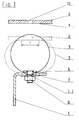
- FIG. 1 shows a first example of a device for Sealing the contact zone between two relative to each other movable system parts 1, 2 shown. It contains an extending along the contact zone, sealing element fastened to the first system part 1 3 and one provided on the second system part 2 and in a closed position of the two parts of the system 1, 2 in contact with the sealing element 3 coming counter surface 4.
- the sealing element 3 is by a resilient Hollow body formed in the with the solid Lines shown in Fig.1 opening position, a circular cross-section transverse to the longitudinal extent having.
- the closed position comes in an arcuate curve Part of the sealing element 3 with the Counter surface 4 resiliently in contact and lies against the Counter surface. This results in the closed position a contact zone with width B.
- the hollow profile body of the sealing element 3 is expediently by a closed in cross section Profile made of spring steel.
- the sealing element has cutouts by the appropriate one Means for fastening the sealing element on reach through the first part of the system.
- a terminal block 6 is provided via recesses in the hollow profile body of the sealing element 3 on the first system part 1 for holding the sealing element is attached.
- the terminal block 6 has for example, a large number in its longitudinal direction spaced threaded bolts on through corresponding recesses in the hollow profile body of the sealing element 3 and by corresponding Grip recesses 1.1 in the first part of the system. Appropriate are then used to attach the bar Nuts 8 on the threaded bolts 7 screwed on.
- the sealing element 3 is between the terminal block 6 and the first system part 1 firmly clamped.
- the circular cross section of the sealing element 3 allows a large travel, so that thermal Strains due to the temperature influence of a existing hot gas can be reliably compensated can. This is the case with a sealing element, for example with a diameter of 60 mm in the unloaded State a travel of about 30 mm possible. Which the resulting relatively large width B of the contact zone also ensures a reliable seal.
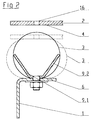
- the second embodiment shown in Fig.2 differs from the variant according to FIG. 1 only in that that additional means of stabilizing the Sealing element 3 are provided.
- the stabilizers are attached to the first system part 1 and are expediently made in one piece with the terminal strip educated. Point in the illustrated embodiment the stabilizing means two legs 9.1 and 9.2 on in the open position of the two parts of the system 1, 2 with their end areas on opposite Bearing areas of the inner wall of the sealing element 3. This causes the sealing element to vibrate naturally 3 even at high flow speeds avoided or reduced.
- approximately V-shaped Stabilizers are also other cross-sectional shapes, for example, a T-shape is conceivable.
- FIG Legs 9.1 and 9.2 Shown in dashed lines in FIG Legs 9.1 and 9.2 normally come in the closed position not with the inner wall of the sealing element in touch. With very large one-sided pressures However, there may be a displacement of the sealing element come, so that the inner wall then on one of the two legs again. Have tried however shown that the seal shown itself at Pressure of 120 mbar is still stable. Only with larger ones Press one of the two legs as a support and this prevents the seal from lifting off.
- the sealing element 3 according to FIG. 3 again corresponds the embodiment of Figure 1, but a additional spring steel sheet 10 in the hollow profile body of the sealing element 3 is inserted, the spring steel sheet 10 on the inner wall of the hollow profile body is present.
- this additional spring steel sheet 10 can increase the spring force of the sealing element. Since the spring steel sheet 10 is only inserted the spring force can also, if necessary subsequently increased or adjusted.
- FIG. 4 shows that again Sealing element 3 according to Figure 1, being in the sealing element 3 a second inner hollow profile body 11 with smaller cross-sectional shape is arranged. Also the second hollow profile body 11 preferably has one circular cross section. The sealing element 3 and the second hollow profile body 11 are expedient together through the terminal block 6 on the first part of the system clamped.
- the second hollow profile body 11 is inside the sealing element 3 arranged that during the closing process first the outer hollow profile body when touched is deformed with the counter surface 4 and with increasing Deformation of the outer hollow profile body too the second hollow profile body 11 is deformed.
- sealing device is thus as long only the sealing element 3 deforms, initially softer and then becomes more deformed of the second hollow profile body 11 significantly harder.
- the first plant part 1 is expediently in the area the attachment of the sealing element 3 in such a way trained that the sealing element 3 in the Support the closed position on the first part of the system.
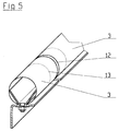
- the sealing devices described above are for example used for swing or swing flaps, their width and height or length up to 10 m or more. From manufacturing technology Reasons on the one hand and on the other hand the assembly too facilitate, the sealing elements 3 are expedient in a variety of arranged one behind the other Assembled pieces of, for example, one meter (see Fig. 5). To thermal longitudinal expansion of the To allow sealing elements 3 is between two adjacent seal elements a gap 12 left. In order to guarantee a gas-tight seal, half a connecting sleeve 13 inserted into both sealing elements 3. The connecting sleeve 13 is also advantageously made of spring steel manufactured.
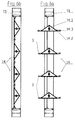
- FIGS. 6A and 6B there is a rotary flap with four Venetian blind swiveling wings 14 in the Open or closed position shown.
- the rotary wing exist in the illustrated embodiment from a latticework 14.1, a wing plate 14.2 and a pivot axis 14.3.
- the rotary blades are with their Pivot axes 14.3 stored in a frame 15.
- Sealing devices according to the type described above intended.
- a detailed view in the area of the sealing device between two rotary blades 14 is in Fig.7 shown in more detail.
- the sealing element 3 is on one of the two rotary wings 14 arranged while the Counter surface is provided on the other rotary wing.
- the sealing device is not based on that in Fig. 7 illustrated embodiment limited. So can for example also those illustrated in FIGS. 1, 3 and 4 Variants are provided.
- the butterfly valve shows, can Sealing device between both movable Plant parts (rotary blades 14) and between one movable plant part (rotating wing 14) and a fixed Plant part (frame 15) are arranged.
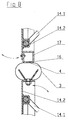
- Fig. 8 shows a further embodiment of the in Fig. 7 illustrated sealing device.
- the peculiarity of this Embodiment is that in the counter surface 4 means for feeding along the contact zone of sealing air are provided. This means expediently formed by a slot 16; through the sealing air in the area of the contact zone can be pressed.
- the counter surface 4 is expediently by an outer surface of a hollow profile body 17 formed, one in the outer surface mouth and extending along the contact zone Has slot 16.
- the hollow profile body 17th is carried out, for example, through a square tube.
- Sealing element 13 Due to the large travel of the circular cross section Sealing element 13 forms on the corresponding Counter surface a relatively wide contact zone out, which is in particular for the supply of sealing air Suitable dimensions.
- the sealing element 3 should therefore deform in the closed position so that it lies flat against the flat counter surface.
- 9 and 10 is another application for the sealing device described above is shown.
- 9 shows a top view of a branching of a hot gas pipeline.
- the hot gas flows according to arrow 18 into this branch area and will then depending on Position of a swivel flap 21 either in the direction forwarded by arrow 19 or in the direction of arrow 20.
- that would Hot gas can be derived in the direction of arrow 19.
- the swivel flap 21 can thus either one or shut off another branch.
- a sealing device provided, for example, according to one of the Embodiments described above formed can be.
- the sealing element 3 is here on the Swing flap 21 attached and acts with a corresponding Counter surface 4 together.
- the counter surface again has means for supplying sealing air, which are formed by a slot 16 in the Counter surface 4 opens.
- the sealing air is, for example supplied via a hollow profile body 17, the counter surface 4 on an outer surface of the hollow profile body 17 is formed.
- the means for supplying sealing air can, if necessary also in the other exemplary embodiments described (Fig. 1 to 4) can be provided.
- a corresponding slot 16 in indicated the opposite surface.
- the sealing device according to the invention can also be used without the supply of sealing air.
- sealing air When using sealing air, however, one hundred percent Seals can be achieved. However, there is not the need to seal the air in the area to the contact zone. It would also be conceivable arrange two sealing elements next to each other, which in the closed position on a common counter surface issue. The slot for the sealing air could then be in open the space between the two sealing elements.
- sealing element is circular in cross section 3 especially for the supply of Sealing air in the area of the contact zone are suitable however, other cross-sectional shapes of sealing elements conceivable, but for a good seal attention to the widest possible contact zone should.
Abstract
Description
- Fig.1
- eine schematische Schnittdarstellung der Vorrichtung zur Abdichtung gemäß einem ersten Ausführungsbeispiel,
- Fig.2
- eine schematische Schnittdarstellung der Vorrichtung zur Abdichtung gemäß einem zweiten Ausführungsbeispiel,
- Fig.3
- eine schematische Schnittdarstellung des Dichtungselements gemäß einem dritten Ausführungsbeispiel,
- Fig.4
- eine schematische Schnittdarstellung des Dichtungselements gemäß einem vierten Ausführungsbeispiel,
- Fig.5
- eine dreidimensionale Darstellung im Verbindungsbereich zweier Dichtungselemente,
- Fig.6A und 6B
- eine schematische Darstellung einer Drehflügelklappe in der Öffnungs- bzw. Schließstellung der Drehflügel,
- Fig.7
- eine geschnittene Teilansicht zweier Drehflügel in der Schließstellung gemäß einer ersten Variante,
- Fig.8
- eine geschnittene Teilansicht zweier Drehflügel in der Schließstellung gemäß einer zweiten Variante,
- Fig.9
- eine Schnittdarstellung einer Anlage mit einer Schwenkflügelklappe und
- Fig.10
- eine Schnittdarstellung des Details X der Fig.9.
Claims (18)
- Vorrichtung zur Abdichtung der Berührungszone zwischen zwei relativ zueinander beweglichen Anlagenteilen (1, 2), enthaltend ein sich entlang der Berührungszone erstreckendes, am ersten Anlagenteil (1) befestigtes Dichtungselement (3) sowie eine am zweiten Anlagenteil (2) vorgesehene und in einer Schließstellung der beiden Anlagenteile mit dem Dichtungselement in Berührung kommende Gegenfläche (4), wobei das Dichtungselement durch einen federelastischen Hohlprofilkörper gebildet wird, der quer zu seiner Längserstreckung einen in einer Öffnungsstellung der beiden Anlagenteile bogenförmig gekrümmten Teilbereich aufweist, der sich in der Schließstellung der beiden Anlagenteile federnd an die Gegenfläche anlegt,
dadurch gekennzeichnet, daß der Hohlprofilkörper - in einer Öffnungsstellung - quer zu seiner Längserstreckung eine kreisförmigen Querschnitt aufweist. - Vorrichtung nach Anspruch 1, dadurch gekennzeichnet, daß der Hohlprofilkörper durch ein im Querschnitt geschlossenes Profil aus Federstahl gebildet wird.
- Vorrichtung nach einem oder mehreren der vorhergehenden Ansprüche, dadurch gekennzeichnet, daß im Inneren des Hohlprofilkörpers wenigstens eine Klemmleiste vorgesehen ist, die über Aussparungen im Hohlprofilkörper am ersten Anlagenteil zur Halterung des Dichtelements (3) befestigt ist.
- Vorrichtung nach einem oder mehreren der vorhergehenden Ansprüche, dadurch gekennzeichnet, daß das Dichtungselement (3) im Bereich seiner Befestigung am ersten Anlagenteil (1) Aussparungen aufweist, durch die Mittel zur Befestigung des Dichtungselements am ersten Anlagenteil hindurchgreifen.
- Vorrichtung nach einem oder mehreren der vorhergehenden Ansprüche, gekennzeichnet durch im Hohlprofil angeordnete und am ersten Anlagenteil befestigte Mittel zur Stabilisierung des Hohlprofilkörpers.
- Vorrichtung nach Anspruch 3 und 5, dadurch gekennzeichnet, daß die Klemmleiste (6) und die Stabilisierungsmittel einstückig ausgebildet sind.
- Vorrichtung nach einem oder mehreren der vorhergehenden Ansprüche, gekennzeichnet durch im Hohlprofilkörper angeordnete und am ersten Anlagenteil befestigte Mittel zur Stabilisierung des Hohlprofilkörpers, die im Querschnitt wenigstens zwei Schenkel (9.1, 9.2) aufweisen, die in der Öffnungsstellung der beiden Anlagenteile mit ihren Endbereichen an gegenüberliegenden Bereichen der Innenwandung des Hohlprofilkörpers anliegen.
- Vorrichtung nach einem oder mehreren der vorhergehenden Ansprüche, dadurch gekennzeichnet, daß zur Erhöhung der Federkraft des Dichtungselements ein Federstahlblech in das Dichtungselement einschiebbar ist, das an der Innenwandung des Dichtungselements (3) anliegt.
- Vorrichtung nach einem oder mehreren der vorhergehenden Ansprüche, dadurch gekennzeichnet, daß im Dichtungselement (3) ein zweiter innerer Hohlprofilkörper (11) mit kleinerem kreisförmigen Querschnitt derart angeordnet ist, daß beim Schließvorgang zunächst der äußere Hohlprofilkörper bei Berührung der Gegenfläche (4) verformt wird und mit zunehmender Verformung des äußeren Hohlprofilkörpers auch der innere Hohlprofilkörper (11) verformt wird.
- Vorrichtung nach einem oder mehreren der vorhergehenden Ansprüche, dadurch gekennzeichnet, daß die Gegenfläche (4) eben ausgebildet ist und das Dichtungselement (3) in der Schließstellung derart verformt ist, daß es in der Berührungszone plan an der Gegenfläche anliegt.
- Vorrichtung nach einem oder mehreren der vorhergehenden Ansprüche, dadurch gekennzeichnet, daß die Gegenfläche (4) entlang der Berührungszone Mittel zur Zuführung von Sperrluft aufweist.
- Vorrichtung nach einem oder mehreren der vorhergehenden Ansprüche, dadurch gekennzeichnet, daß die Gegenfläche (4) entlang der Berührungszone einen Schlitz (16) zur Zuführung von Sperrluft aufweist.
- Vorrichtung nach einem oder mehreren der vorhergehenden Ansprüche, dadurch gekennzeichnet, daß die Gegenfläche (4) durch eine Außenfläche eines Hohlprofilkörpers (17) gebildet wird, der einen in der Außenfläche mündenden und sich entlang der Berührungszone erstreckenden Schlitz aufweist, über den Sperrluft zuführbar ist.
- Vorrichtung zur Abdichtung der Berührungszone zwischen zwei relativ zueinander beweglichen Anlagenteilen (1, 2), enthaltend ein sich entlang der Berührungszone erstreckendes am ersten Anlagenteil (1) befestigtes Dichtungselement (3) sowie eine am zweiten Anlagenteil (2) vorgesehene und in einer Schließstellung der beiden Anlagenteile mit dem Dichtungselement (3) in Berührung kommende Gegenfläche (4),
wobei sich das Dichtungselement in der Schließstellung der beiden Anlagenteile federnd an die Gegenfläche anlegt,
dadurch gekennzeichnet, daß die Gegenfläche im Bereich der Berührungszone mit dem Dichtungselement Mittel zur Zuführung von Sperrluft aufweist. - Vorrichtung nach Anspruch 14, dadurch gekennzeichnet, daß die Mittel zur Zuführung von Sperrluft durch einen entlang der Berührungszone verlaufenden Schlitz (16) gebildet werden.
- Vorrichtung nach Anspruch 14 und/oder 15, dadurch gekennzeichnet, daß das Dichtungselement (3) durch einen feder-elastischen Hohlkörper gebildet wird, der - in einer Öffnungsstellung - quer zu seiner Längserstreckung einen kreisförmigen Querschnitt aufweist.
- Vorrichtung nach einem oder mehreren der Ansprüche 14 bis 16, gekennzeichnet durch eine Ausgestaltung des Dichtungselements nach einem oder mehreren der Ansprüche 1 bis 10.
- Vorrichtung nach einem oder mehreren der vorhergehenden Ansprüche, dadurch gekennzeichnet, daß der Anlagenteil (1) im Bereich der Befestigung des Dichtungselements (3) derart ausgebildet ist, daß sich das Dichtungselement in der Schließstellung am ersten Anlagenteil abstützt.
Applications Claiming Priority (2)
| Application Number | Priority Date | Filing Date | Title |
|---|---|---|---|
| DE19949370A DE19949370A1 (de) | 1999-10-13 | 1999-10-13 | Vorrichtung zur Abdichtung |
| DE19949370 | 1999-10-13 |
Publications (3)
| Publication Number | Publication Date |
|---|---|
| EP1092899A2 true EP1092899A2 (de) | 2001-04-18 |
| EP1092899A3 EP1092899A3 (de) | 2003-05-02 |
| EP1092899B1 EP1092899B1 (de) | 2005-12-21 |
Family
ID=7925504
Family Applications (1)
| Application Number | Title | Priority Date | Filing Date |
|---|---|---|---|
| EP00122165A Expired - Lifetime EP1092899B1 (de) | 1999-10-13 | 2000-10-12 | Vorrichtung zur Abdichtung |
Country Status (5)
| Country | Link |
|---|---|
| US (1) | US6588768B1 (de) |
| EP (1) | EP1092899B1 (de) |
| AT (1) | ATE313744T1 (de) |
| DE (2) | DE19949370A1 (de) |
| ES (1) | ES2250063T3 (de) |
Cited By (2)
| Publication number | Priority date | Publication date | Assignee | Title |
|---|---|---|---|---|
| EP1873426A2 (de) | 2006-06-30 | 2008-01-02 | General Electric Company | Dichtungsanordnung |
| AT514432B1 (de) * | 2013-05-22 | 2015-01-15 | Compact Power Plant Products Gmbh | Gasweiche |
Families Citing this family (5)
| Publication number | Priority date | Publication date | Assignee | Title |
|---|---|---|---|---|
| DE102007016554A1 (de) | 2007-04-05 | 2008-10-09 | Janich Gmbh & Co. Kg | Absperrsystem für große Leitungsquerschnitte mit einer Schwenkklappe |
| WO2009134874A1 (en) | 2008-04-29 | 2009-11-05 | Thermal Structures, Inc. | Thermal seal and methods therefor |
| DE102009020843A1 (de) | 2009-05-12 | 2010-11-25 | Janich Gmbh & Co. Kg | Absperrsystem mit einer Schwenkklappe für große Leistungsquerschnitte |
| US9618118B2 (en) * | 2013-05-23 | 2017-04-11 | Alaska Airlines, Inc. | Air seal assembly for aircraft flap seal |
| GB201908783D0 (en) * | 2019-06-19 | 2019-07-31 | Tokamak Energy Ltd | Metal sealing ring and method of forming a metal-to-metal seal |
Citations (1)
| Publication number | Priority date | Publication date | Assignee | Title |
|---|---|---|---|---|
| EP0340430A2 (de) | 1988-05-05 | 1989-11-08 | MANNESMANN Aktiengesellschaft | Vorrichtung zur Abdichtung |
Family Cites Families (21)
| Publication number | Priority date | Publication date | Assignee | Title |
|---|---|---|---|---|
| US2345743A (en) * | 1941-03-06 | 1944-04-04 | Sunbeam Electric Mfg Company | Refrigerator gasket |
| US2891289A (en) * | 1957-12-16 | 1959-06-23 | Guilbert Inc | Safety astragal for freight elevator doors |
| US3154311A (en) * | 1961-10-03 | 1964-10-27 | Gen Electric | Sealing means |
| DE1751550C3 (de) * | 1968-06-18 | 1975-04-17 | Messerschmitt-Boelkow-Blohm Gmbh, 8000 Muenchen | Dichtung zwischen dem Einlauf eines Strahltriebwerkes und einem zellenfesten Aufnahmering des Einlaufgehäuses |
| US4077432A (en) * | 1977-01-05 | 1978-03-07 | Mosser Industries, Inc. | Purged valve |
| US4214571A (en) * | 1978-01-16 | 1980-07-29 | Chambers Corporation | Removable oven panel and door sealing gasket |
| DE3208906A1 (de) * | 1982-03-12 | 1983-09-22 | Hermann Rappold & Co GmbH, 5160 Düren | Absperr- oder drosselarmatur mit einer aus einem biegeelastischen streifen gefertigten dichtung |
| US4493430A (en) * | 1982-10-04 | 1985-01-15 | Chicago Bridge & Iron Company | Floating roof seal using a coil spring |
| DE3433346A1 (de) * | 1984-09-11 | 1986-03-20 | Krupp Polysius Ag, 4720 Beckum | Vorrichtung zum absperren einer rohrleitung |
| US4822060A (en) * | 1985-02-21 | 1989-04-18 | The Bentley-Harris Manufacturing Company | Woven tubular gasket with continuous integral attachment means |
| US4892116A (en) * | 1986-12-17 | 1990-01-09 | Grasseschi John J | Plumbing sealing system |
| US4724863A (en) * | 1987-05-21 | 1988-02-16 | Connor Peter J | Flue gas seal |
| US5193823A (en) * | 1988-05-05 | 1993-03-16 | Mannesmann Aktiengesellschaft | Resilient metallic sealing member |
| DE3815404C2 (de) * | 1988-05-05 | 1996-07-18 | Mannesmann Ag | Schwenkklappenanordnung für Heißgas-Rohrleitungen |
| DE4030611A1 (de) * | 1990-09-27 | 1992-04-02 | Mannesmann Ag | Absperrorgan |
| DE4122451C1 (en) * | 1991-07-06 | 1993-03-11 | Neuman & Esser Maschinenfabrik, 5132 Uebach-Palenberg, De | Stuffing box for toxic gas compressor - includes seals and flushing gas chambers with flushing gas connection tangential to piston rod |
| DE4122605A1 (de) * | 1991-07-08 | 1993-01-14 | Zur Steege Geb Hinze Ellen | Absperrarmatur |
| DE4322806A1 (de) * | 1993-07-08 | 1995-01-12 | Janich Gmbh & Co | Vorrichtung zur Abdichtung zwischen zwei Anlagenteilen |
| DE19521916A1 (de) * | 1995-06-09 | 1996-12-12 | Mannesmann Ag | Vorrichtung zur Abdichtung zwischen beweglichen Anlagenteilen |
| DE19521915A1 (de) * | 1995-06-09 | 1996-12-12 | Mannesmann Ag | Vorrichtung zur Abdichtung zwischen beweglichen Anlagenteilen |
| DE19828896C1 (de) * | 1998-06-19 | 1999-09-09 | Mannesmann Ag | Vorrichtung zur Abdichtung |
-
1999
- 1999-10-13 DE DE19949370A patent/DE19949370A1/de not_active Withdrawn
-
2000
- 2000-10-11 US US09/686,218 patent/US6588768B1/en not_active Expired - Fee Related
- 2000-10-12 AT AT00122165T patent/ATE313744T1/de not_active IP Right Cessation
- 2000-10-12 ES ES00122165T patent/ES2250063T3/es not_active Expired - Lifetime
- 2000-10-12 DE DE50011897T patent/DE50011897D1/de not_active Expired - Lifetime
- 2000-10-12 EP EP00122165A patent/EP1092899B1/de not_active Expired - Lifetime
Patent Citations (1)
| Publication number | Priority date | Publication date | Assignee | Title |
|---|---|---|---|---|
| EP0340430A2 (de) | 1988-05-05 | 1989-11-08 | MANNESMANN Aktiengesellschaft | Vorrichtung zur Abdichtung |
Cited By (6)
| Publication number | Priority date | Publication date | Assignee | Title |
|---|---|---|---|---|
| EP1873426A2 (de) | 2006-06-30 | 2008-01-02 | General Electric Company | Dichtungsanordnung |
| JP2008014491A (ja) * | 2006-06-30 | 2008-01-24 | General Electric Co <Ge> | シールアセンブリ |
| EP1873426A3 (de) * | 2006-06-30 | 2009-10-21 | General Electric Company | Dichtungsanordnung |
| US7775048B2 (en) | 2006-06-30 | 2010-08-17 | General Electric Company | Seal assembly |
| AT514432B1 (de) * | 2013-05-22 | 2015-01-15 | Compact Power Plant Products Gmbh | Gasweiche |
| AT514432A4 (de) * | 2013-05-22 | 2015-01-15 | Compact Power Plant Products Gmbh | Gasweiche |
Also Published As
| Publication number | Publication date |
|---|---|
| EP1092899A3 (de) | 2003-05-02 |
| DE19949370A1 (de) | 2001-04-19 |
| EP1092899B1 (de) | 2005-12-21 |
| ATE313744T1 (de) | 2006-01-15 |
| ES2250063T3 (es) | 2006-04-16 |
| US6588768B1 (en) | 2003-07-08 |
| DE50011897D1 (de) | 2006-01-26 |
Similar Documents
| Publication | Publication Date | Title |
|---|---|---|
| DE102010053411B4 (de) | Vakuumventil | |
| DE3313235C2 (de) | ||
| EP2078892B1 (de) | Vakuum-Ventil mit Dichtring | |
| DE2730307C2 (de) | Flanschverbindung zum gegenseitigen Befestigen von im Querschnitt im wesentlichen rechteckigen Kanalteilstücken aus Blech | |
| EP0041729B1 (de) | Schlitzdüse zur Bildung von zusammenhängenden Gas- oder Flüssigkeitsschleiern, beispielsweise für Brenner | |
| DE4137038C1 (en) | Radiator case for front body of motor vehicle - has distance pieces, one elastic, to clamp flat tube heat exchanger between frame and collectors | |
| EP1092899A2 (de) | Vorrichtung zur Abdichtung | |
| DE3815402A1 (de) | Vorrichtung zur abdichtung | |
| DE19644159A1 (de) | Heiz- oder Klimaanlage | |
| DE202018102557U1 (de) | Abwasser-Plattenschieber | |
| DE102017120003A1 (de) | Luftausströmer für ein Fahrzeug | |
| EP0830529B1 (de) | Vorrichtung zur abdichtung zwischen beweglichen anlagenteilen | |
| DE19521916A1 (de) | Vorrichtung zur Abdichtung zwischen beweglichen Anlagenteilen | |
| EP0328914A2 (de) | Drehschieberanordnung | |
| EP1783317A2 (de) | Befestigungsclip für ein Tragprofil einer Verschattungsanlage | |
| DE19828896C1 (de) | Vorrichtung zur Abdichtung | |
| DE3600236A1 (de) | Wischblatt fuer kraftfahrzeuge | |
| EP1226364A1 (de) | Führungsschiene für ein linearlager | |
| EP0487904A2 (de) | Absperrarmatur mit Querdichtung | |
| DE10155940A1 (de) | Klappe zur Verwendung in Rauchgas- oder Luftkanälen | |
| DE3332337C2 (de) | Dachwindabweiser für Kraftfahrzeuge | |
| DE2820208A1 (de) | Absperrvorrichtung, insbesondere druckentlastungsjalousie | |
| DE102016106934A1 (de) | Dichtung und Fensterelement | |
| EP0223174A1 (de) | Rahmenprofil | |
| DE19906174C1 (de) | Vorrichtung zur Abdichtung |
Legal Events
| Date | Code | Title | Description |
|---|---|---|---|
| PUAI | Public reference made under article 153(3) epc to a published international application that has entered the european phase |
Free format text: ORIGINAL CODE: 0009012 |
|
| AK | Designated contracting states |
Kind code of ref document: A2 Designated state(s): AT BE CH CY DE DK ES FI FR GB GR IE IT LI LU MC NL PT SE |
|
| AX | Request for extension of the european patent |
Free format text: AL;LT;LV;MK;RO;SI |
|
| PUAL | Search report despatched |
Free format text: ORIGINAL CODE: 0009013 |
|
| AK | Designated contracting states |
Designated state(s): AT BE CH CY DE DK ES FI FR GB GR IE IT LI LU MC NL PT SE |
|
| AX | Request for extension of the european patent |
Extension state: AL LT LV MK RO SI |
|
| 17P | Request for examination filed |
Effective date: 20030410 |
|
| AKX | Designation fees paid |
Designated state(s): AT BE CH CY DE DK ES FI FR GB GR IE IT LI LU MC NL PT SE |
|
| 17Q | First examination report despatched |
Effective date: 20040518 |
|
| GRAP | Despatch of communication of intention to grant a patent |
Free format text: ORIGINAL CODE: EPIDOSNIGR1 |
|
| GRAS | Grant fee paid |
Free format text: ORIGINAL CODE: EPIDOSNIGR3 |
|
| GRAA | (expected) grant |
Free format text: ORIGINAL CODE: 0009210 |
|
| AK | Designated contracting states |
Kind code of ref document: B1 Designated state(s): AT BE CH CY DE DK ES FI FR GB GR IE IT LI LU MC NL PT SE |
|
| PG25 | Lapsed in a contracting state [announced via postgrant information from national office to epo] |
Ref country code: IT Free format text: LAPSE BECAUSE OF FAILURE TO SUBMIT A TRANSLATION OF THE DESCRIPTION OR TO PAY THE FEE WITHIN THE PRESCRIBED TIME-LIMIT;WARNING: LAPSES OF ITALIAN PATENTS WITH EFFECTIVE DATE BEFORE 2007 MAY HAVE OCCURRED AT ANY TIME BEFORE 2007. THE CORRECT EFFECTIVE DATE MAY BE DIFFERENT FROM THE ONE RECORDED. Effective date: 20051221 Ref country code: IE Free format text: LAPSE BECAUSE OF FAILURE TO SUBMIT A TRANSLATION OF THE DESCRIPTION OR TO PAY THE FEE WITHIN THE PRESCRIBED TIME-LIMIT Effective date: 20051221 |
|
| REG | Reference to a national code |
Ref country code: GB Ref legal event code: FG4D Free format text: NOT ENGLISH |
|
| REG | Reference to a national code |
Ref country code: CH Ref legal event code: EP |
|
| REG | Reference to a national code |
Ref country code: IE Ref legal event code: FG4D Free format text: LANGUAGE OF EP DOCUMENT: GERMAN |
|
| REF | Corresponds to: |
Ref document number: 50011897 Country of ref document: DE Date of ref document: 20060126 Kind code of ref document: P |
|
| GBT | Gb: translation of ep patent filed (gb section 77(6)(a)/1977) |
Effective date: 20060220 |
|
| PG25 | Lapsed in a contracting state [announced via postgrant information from national office to epo] |
Ref country code: DK Free format text: LAPSE BECAUSE OF FAILURE TO SUBMIT A TRANSLATION OF THE DESCRIPTION OR TO PAY THE FEE WITHIN THE PRESCRIBED TIME-LIMIT Effective date: 20060321 Ref country code: SE Free format text: LAPSE BECAUSE OF FAILURE TO SUBMIT A TRANSLATION OF THE DESCRIPTION OR TO PAY THE FEE WITHIN THE PRESCRIBED TIME-LIMIT Effective date: 20060321 Ref country code: GR Free format text: LAPSE BECAUSE OF FAILURE TO SUBMIT A TRANSLATION OF THE DESCRIPTION OR TO PAY THE FEE WITHIN THE PRESCRIBED TIME-LIMIT Effective date: 20060321 |
|
| REG | Reference to a national code |
Ref country code: ES Ref legal event code: FG2A Ref document number: 2250063 Country of ref document: ES Kind code of ref document: T3 |
|
| PG25 | Lapsed in a contracting state [announced via postgrant information from national office to epo] |
Ref country code: PT Free format text: LAPSE BECAUSE OF FAILURE TO SUBMIT A TRANSLATION OF THE DESCRIPTION OR TO PAY THE FEE WITHIN THE PRESCRIBED TIME-LIMIT Effective date: 20060522 |
|
| ET | Fr: translation filed | ||
| REG | Reference to a national code |
Ref country code: IE Ref legal event code: FD4D |
|
| PLBE | No opposition filed within time limit |
Free format text: ORIGINAL CODE: 0009261 |
|
| STAA | Information on the status of an ep patent application or granted ep patent |
Free format text: STATUS: NO OPPOSITION FILED WITHIN TIME LIMIT |
|
| PG25 | Lapsed in a contracting state [announced via postgrant information from national office to epo] |
Ref country code: LI Free format text: LAPSE BECAUSE OF NON-PAYMENT OF DUE FEES Effective date: 20061031 Ref country code: MC Free format text: LAPSE BECAUSE OF NON-PAYMENT OF DUE FEES Effective date: 20061031 Ref country code: CH Free format text: LAPSE BECAUSE OF NON-PAYMENT OF DUE FEES Effective date: 20061031 |
|
| 26N | No opposition filed |
Effective date: 20060922 |
|
| REG | Reference to a national code |
Ref country code: CH Ref legal event code: PL |
|
| PG25 | Lapsed in a contracting state [announced via postgrant information from national office to epo] |
Ref country code: AT Free format text: LAPSE BECAUSE OF NON-PAYMENT OF DUE FEES Effective date: 20061012 |
|
| PG25 | Lapsed in a contracting state [announced via postgrant information from national office to epo] |
Ref country code: LU Free format text: LAPSE BECAUSE OF NON-PAYMENT OF DUE FEES Effective date: 20061012 |
|
| PG25 | Lapsed in a contracting state [announced via postgrant information from national office to epo] |
Ref country code: CY Free format text: LAPSE BECAUSE OF FAILURE TO SUBMIT A TRANSLATION OF THE DESCRIPTION OR TO PAY THE FEE WITHIN THE PRESCRIBED TIME-LIMIT Effective date: 20051221 |
|
| REG | Reference to a national code |
Ref country code: FR Ref legal event code: PLFP Year of fee payment: 16 |
|
| PGFP | Annual fee paid to national office [announced via postgrant information from national office to epo] |
Ref country code: IT Payment date: 20151026 Year of fee payment: 16 Ref country code: GB Payment date: 20151021 Year of fee payment: 16 Ref country code: FI Payment date: 20151013 Year of fee payment: 16 |
|
| PGFP | Annual fee paid to national office [announced via postgrant information from national office to epo] |
Ref country code: NL Payment date: 20151021 Year of fee payment: 16 Ref country code: BE Payment date: 20151021 Year of fee payment: 16 Ref country code: ES Payment date: 20151021 Year of fee payment: 16 Ref country code: FR Payment date: 20151023 Year of fee payment: 16 |
|
| PGFP | Annual fee paid to national office [announced via postgrant information from national office to epo] |
Ref country code: DE Payment date: 20151217 Year of fee payment: 16 |
|
| PG25 | Lapsed in a contracting state [announced via postgrant information from national office to epo] |
Ref country code: BE Free format text: LAPSE BECAUSE OF NON-PAYMENT OF DUE FEES Effective date: 20161031 |
|
| REG | Reference to a national code |
Ref country code: DE Ref legal event code: R119 Ref document number: 50011897 Country of ref document: DE |
|
| REG | Reference to a national code |
Ref country code: NL Ref legal event code: MM Effective date: 20161101 |
|
| GBPC | Gb: european patent ceased through non-payment of renewal fee |
Effective date: 20161012 |
|
| REG | Reference to a national code |
Ref country code: FR Ref legal event code: ST Effective date: 20170630 |
|
| PG25 | Lapsed in a contracting state [announced via postgrant information from national office to epo] |
Ref country code: FI Free format text: LAPSE BECAUSE OF NON-PAYMENT OF DUE FEES Effective date: 20161012 Ref country code: DE Free format text: LAPSE BECAUSE OF NON-PAYMENT OF DUE FEES Effective date: 20170503 Ref country code: FR Free format text: LAPSE BECAUSE OF NON-PAYMENT OF DUE FEES Effective date: 20161102 Ref country code: GB Free format text: LAPSE BECAUSE OF NON-PAYMENT OF DUE FEES Effective date: 20161012 |
|
| PG25 | Lapsed in a contracting state [announced via postgrant information from national office to epo] |
Ref country code: NL Free format text: LAPSE BECAUSE OF NON-PAYMENT OF DUE FEES Effective date: 20161101 |
|
| PG25 | Lapsed in a contracting state [announced via postgrant information from national office to epo] |
Ref country code: IT Free format text: LAPSE BECAUSE OF NON-PAYMENT OF DUE FEES Effective date: 20161012 |
|
| REG | Reference to a national code |
Ref country code: BE Ref legal event code: MM Effective date: 20161031 |
|
| PG25 | Lapsed in a contracting state [announced via postgrant information from national office to epo] |
Ref country code: ES Free format text: LAPSE BECAUSE OF FAILURE TO SUBMIT A TRANSLATION OF THE DESCRIPTION OR TO PAY THE FEE WITHIN THE PRESCRIBED TIME-LIMIT Effective date: 20051221 |
|
| REG | Reference to a national code |
Ref country code: ES Ref legal event code: FD2A Effective date: 20180627 |
|
| PG25 | Lapsed in a contracting state [announced via postgrant information from national office to epo] |
Ref country code: ES Free format text: LAPSE BECAUSE OF FAILURE TO SUBMIT A TRANSLATION OF THE DESCRIPTION OR TO PAY THE FEE WITHIN THE PRESCRIBED TIME-LIMIT Effective date: 20161013 |
|
| RIC2 | Information provided on ipc code assigned after grant |
Ipc: F16J 15/08 20060101AFI20001222BHEP |