EP1783317A2 - Befestigungsclip für ein Tragprofil einer Verschattungsanlage - Google Patents
Befestigungsclip für ein Tragprofil einer Verschattungsanlage Download PDFInfo
- Publication number
- EP1783317A2 EP1783317A2 EP06123372A EP06123372A EP1783317A2 EP 1783317 A2 EP1783317 A2 EP 1783317A2 EP 06123372 A EP06123372 A EP 06123372A EP 06123372 A EP06123372 A EP 06123372A EP 1783317 A2 EP1783317 A2 EP 1783317A2
- Authority
- EP
- European Patent Office
- Prior art keywords
- contact surface
- retaining
- support profile
- retaining tabs
- clip
- Prior art date
- Legal status (The legal status is an assumption and is not a legal conclusion. Google has not performed a legal analysis and makes no representation as to the accuracy of the status listed.)
- Granted
Links
Images

Classifications
-
- E—FIXED CONSTRUCTIONS
- E06—DOORS, WINDOWS, SHUTTERS, OR ROLLER BLINDS IN GENERAL; LADDERS
- E06B—FIXED OR MOVABLE CLOSURES FOR OPENINGS IN BUILDINGS, VEHICLES, FENCES OR LIKE ENCLOSURES IN GENERAL, e.g. DOORS, WINDOWS, BLINDS, GATES
- E06B9/00—Screening or protective devices for wall or similar openings, with or without operating or securing mechanisms; Closures of similar construction
- E06B9/24—Screens or other constructions affording protection against light, especially against sunshine; Similar screens for privacy or appearance; Slat blinds
- E06B9/26—Lamellar or like blinds, e.g. venetian blinds
- E06B9/28—Lamellar or like blinds, e.g. venetian blinds with horizontal lamellae, e.g. non-liftable
- E06B9/30—Lamellar or like blinds, e.g. venetian blinds with horizontal lamellae, e.g. non-liftable liftable
- E06B9/32—Operating, guiding, or securing devices therefor
- E06B9/323—Structure or support of upper box
Definitions
- the invention relates to a shading system, in particular a (vertical) blind, roller blind or pleated, with a support profile and a mounting clip for the support profile, which has a contact surface and on both sides of the contact surface oppositely arranged retaining tabs, of which at least one of the retaining tabs resilient connected to the contact surface.
- a mounting clip for such a shading system is well known in practice and shown for example in a component catalog of BENTHIN GmbH, Bremerhaven, Germany for the pleats, page P 20.
- the retaining tabs are resiliently arranged on the contact surface in the fastening clips for pleats according to the above component catalog page P 20.
- This is structurally specifically solved in that the contact surface initially merges into sloping outwardly sloping shoulders. At these oblique shoulders, the retaining tabs are arranged. Due to the sloping shoulders the retaining tabs are seen from the building surface from about 3.5 mm lower than the contact surface, so that between the building surface facing the top of the support profile and the building surface remains a light gap of about 3.5 mm thickness. This is undesirable because visually disturbing.
- the invention is based on the problem to further develop a mounting clip of the type mentioned that the support profile easier and possible without auxiliary tools in the mounting clip and can be solved again by the mounting clip, without a visible light gap between the support profile and building surface available is.
- the fastening clip according to the invention is characterized in that the retaining tab is resiliently connected by means of a bead with the contact surface, wherein the bead is arranged in a recess in the top of the support profile.
- At least one of the retaining tabs Due to the resilient connection of at least one of the retaining tabs with the contact surface, the necessary for releasing the support rail widening of the retaining tabs not only results from the fact that they are bent up elastically. Due to the resilient connection, at least one retaining tab can additionally be pivoted elastically with respect to the contact surface. Specifically, a bead between the contact surface and the respective retaining tab. This bead is bent when loosening the support profile in a sense closing the bead and thus causes a pivoting of the associated retaining tab in the opening direction.
- the invention makes use of the fact that recesses are present in conventional support profiles on their upper side facing the building surface. When inserted in the mounting clip support profile, the bead is in one of these wells.
- At least one of the retaining tabs which although preferred but not necessarily the resiliently connected to the contact surface holding tab must be offset in the direction of the open side of the mounting clip relative to the contact surface arranged.
- This retaining tab is thus spaced slightly from this building surface when bolted to the wall surface contact surface.
- the fastening clip when screwed to a comparatively soft building surface, for example a building surface pasted with a vinyl wallpaper, the fastening clip easily contracts into this building surface (for example vinyl wallpaper).
- a certain pressure is exerted on the retaining tabs, which pivots the retaining tabs in the closing sense. This also complicates the release of the support profile.
- both retaining tabs are formed correspondingly offset. It has proven to be particularly advantageous if the retaining tabs to the thickness of the sheet from which the mounting clip is prepared offset from the contact surface is / are.
- the respective retaining tab or both retaining tabs are spaced as the sheet thickness of the building surface.
- the staggered arrangement can be achieved, for example, by making the bead flatter on its side facing the retaining tab than on its side facing the retaining surface.
- a non-resiliently connected to the contact surface holding tab can be connected by means of a sloping shoulder with the contact surface.
- both retaining tabs may be resiliently connected to the contact surface.
- This can be the retaining tab, which is provided with the grip tab. But it is also quite possible to connect the other retaining tab resiliently with the contact surface. This variant has even proved to be particularly favorable in experiments.
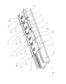
- the fastening clip 10 shown in FIGS. 1 and 2 is screwed by means of a screw 11 under a ceiling, a window reveal, to a wall or directly into a window frame. For the sake of simplicity, these are referred to as building space in the context of this application.
- the fastening clip 10 has a contact surface 12, which is provided with a bore 13. Through this hole 13, the screw 11 is guided. If the fastening clip 10 is screwed tightly to the building surface, the contact surface 12 comes into contact with this building surface.
- the mounting clip 10 is a total of one piece made of a sufficiently elastic material. Specifically, the mounting clip 10 is made of an initially flat metal sheet by appropriate forming. On both sides of the Contact surface 12 are opposing retaining tabs 14, 15 are arranged, which hold a support profile 16 in the form of a particularly good in Fig. 1 recognizable manner. The retaining tabs 14, 15 are so oriented to the contact surface 12 that they form with the contact surface 12 to the support section 16 toward open, substantially U-shaped profile.
- the retaining tabs 15 with the grip tab 17 opposite retaining tab 14 is resiliently connected to the contact surface 12.
- the side of the contact surface 12 facing this retaining tab 14 is bent downward, ie in the direction of the support profile 16 or the open side of the fastening clip 10, to form an upwardly open, U-shaped bead 18.
- This bead 18 goes on its side facing away from the contact surface 12 in a parallel to the contact surface 12 extending, flat portion 19 before it is bent down to the retaining tab 14.
- the bead 18 causes both when inserting the support section 16 in the mounting clip 10, as well as the same when releasing the associated retaining tab 14 is slightly upwards, ie pivoted in the direction of the building surface.
- the bead 18 is in a recess 23, which is located on the side facing the building surface of the support section 16 (top), arranged so that the bead 18 does not strike a viewer. In particular, this does not increase a possible light gap between the building surface and the support profile 16.
- the flat section 19 is arranged downwards, that is to say offset with respect to the stop surface 12, relative to the carrier profile 16. This causes a correspondingly staggered arrangement of the retaining tab 14 relative to the contact surface 12.
- the dimension h of this offset corresponds to the thickness of the metal sheet from which the fastening clip 10 is made.
- the other retaining tab 15 is arranged offset to the contact surface 12, and also about the thickness of the metal sheet. This is effected here by the fact that the retaining tab 15 is connected via an obliquely outwardly sloping shoulder 20 with the contact surface 12.
- FIG. 3 shows some variants of the fastening clip 10.
- the fastening clip 10 described above with reference to FIGS. 1 and 2 is the second fastening clip 10 from the left.
- a fastening clip 10a is shown, which has a bead 18.
- the contact surface 12 is located on the same level as the top of the retaining tabs 14, 15 and therefore also the section 19. Even with a hard building surface, in which the contact surface 12 does not retract when screwing, no light gap remains.
- the fastening clip 10c shown on the right-hand side in turn has two beads 18, 21.
- the sections 19, 22 are offset by the material thickness of the fastening clip 10c relative to the supporting profile 16.
Landscapes
- Engineering & Computer Science (AREA)
- Structural Engineering (AREA)
- Architecture (AREA)
- Civil Engineering (AREA)
- Clamps And Clips (AREA)
- Sheet Holders (AREA)
- Paper (AREA)
- Slide Fasteners, Snap Fasteners, And Hook Fasteners (AREA)
- Absorbent Articles And Supports Therefor (AREA)
- Gripping Jigs, Holding Jigs, And Positioning Jigs (AREA)
- Connection Of Plates (AREA)
- Blinds (AREA)
Abstract
Description
- Die Erfindung betrifft eine Verschattungsanlage, insbesondere einer (Vertikal-) Jalousie, Rollo oder Plissee, mit einen Tragprofil und einem Befestigungsclip für das Tragprofil, welcher eine Anlagefläche und zu beiden Seiten der Anlagefläche einander gegenüberliegend angeordnete Haltelaschen aufweist, von denen wenigstens eine der Haltelaschen federnd mit der Anlagefläche verbunden ist.
- Ein Befestigungsclip für eine solche Verschattungsanlage ist aus der Praxis allgemein bekannt und zum Beispiel in einem Komponentenkatalog der BENTHIN GmbH, Bremerhaven, Deutschland für die Plissees, Seite P 20 gezeigt.
- Innerhalb der Anlagefläche ist eine Bohrung vorgesehen, mittels derer der Befestigungsclip an eine Wand, in eine Fensterleibung oder unter die Zimmerdecke, welche nachfolgend kurz als Gebäudefläche bezeichnet wird, geschraubt werden kann. Die Anlagefläche liegt dann an der entsprechenden Gebäudefläche an. Zu beiden Seiten der Anlagefläche sind einander gegenüberliegend die Haltelaschen angeordnet, wobei eine der Haltelaschen mit einer Grifflasche versehen ist, welche zum einen dazu dient, das Tragprofil in den Befestigungsclip einzuclippen. Das Tragprofil wird nämlich zunächst schräg in die eine Haltelasche eingesetzt und dann nach oben gedrückt, wobei sich die Haltelaschen durch die Grifflasche gleichsam aufbiegen und dadurch das Tragprofil in dem Befestigungsclip bzw. hinter dessen Haltelaschen einschnappen kann. Zum anderen dient die Grifflasche dazu, die zugehörige Haltelasche manuell aufbiegen zu können, falls das Tragprofil einmal demontiert werden muß. Das Aufbiegen der Haltelaschen ist dabei selbstverständlich nur elastischer Natur. Eine plastische Verformung ist nicht gewollt.
- In einem Komponentenkatalog der BENTHIN GmbH, Bremerhaven, Deutschland für Vertikaljalousien, Seite V 20 sind Befestigungsclips gezeigt, bei denen die Haltelasche direkt an der Anlagefläche angeordnet ist. Diese Befestigungsclips sind sehr steif. Schon das Einsetzen des Profils in diesen Befestigungsclip ist sehr schwierig und nur mit großem Kraftaufwand möglich. Soll das Tragprofil einmal gelöst werden, lassen sich diese Befestigungsclips nur mit hoher Kraft und zum Teil nur unter Verwendung von Hilfswerkzeugen vom Befestigungsclip lösen. Es besteht die Gefahr, daß ein solches Hilfswerkzeug abrutscht und das Tragprofil zerkratzt wird.
- Um den Befestigungsclip elastischer zu gestalten und damit den Kraftaufwand beim Einsetzen des Tragprofils und beim Lösen desselben zu verringern, sind bei den Befestigungsclips für Plissees gemäß der oben genannten Komponentenkatalogseite P 20 die Haltelaschen federnd an der Anlagefläche angeordnet. Dieses ist konstruktiv konkret dadurch gelöst, daß die Anlagefläche zunächst in schräg nach außen abfallende Schultern übergeht. An diesen schrägen Schultern sind die Haltelaschen angeordnet. Aufgrund der schräg abfallenden Schultern sind die Haltelaschen von der Gebäudefläche aus gesehen etwa 3,5 mm tiefer angeordnet, als die Anlagefläche, so daß zwischen der der Gebäudefläche zugewandten Oberseite des Tragprofils und der Gebäudefläche ein Lichtspalt von etwa 3,5 mm Dicke verbleibt. Dieses ist unerwünscht, da optisch störend.
- Ferner sind aus der
DE 297 02 782 U1 , derUS 2002/0079067 A1 , derDE 1 954 544 U und derDE 80 34 656 U1 Maßnahmen bekannt, welche das Einsetzen und Entfernen des Tragprofils aus dem Befestigungsclip erleichtern sollen. Diese Bedingen aber wiederum einen größeren Lichtspalt. - Hiervon ausgehend liegt der Erfindung das Problem zugrunde, einen Befestigungsclip der eingangsgenannten Art derart weiter zu bilden, daß sich das Tragprofil leichter und möglichst ohne Hilfswerkzeuge in den Befestigungsclip einsetzen und wieder von dem Befestigungsclip lösen läßt, ohne daß ein sichtbarer Lichtspalt zwischen Tragprofil und Gebäudefläche vorhanden ist.
- Zur Lösung dieses Problems ist der erfindungsgemäße Befestigungsclip dadurch gekennzeichnet, daß die Haltelasche mittels einer Sicke federnd mit der Anlagefläche verbunden ist, wobei die Sicke in einer Vertiefung in der Oberseite des Tragprofils angeordnet ist.
- Durch die federnde Verbindung wenigstens einer der Haltelaschen mit der Anlagefläche ergibt sich die zum Lösen der Tragschiene erforderliche Aufweitung der Haltelaschen nicht nur dadurch, daß diese elastisch aufgebogen werden. Durch die federnde Verbindung kann wenigstens eine Haltelasche zusätzlich elastisch gegenüber der Anlagefläche verschwenkt werden. Konkret ist eine Sicke zwischen der Anlagefläche und der betreffenden Haltelasche. Diese Sicke wird beim Lösen des Tragprofils in einem die Sicke verschließenden Sinne zusammengebogen und bewirkt so ein Verschwenken der zugehörigen Haltelasche im öffnenden Sinne. Die Erfindung macht sich dabei zunutze, daß in üblichen Tragprofilen an ihrer der Gebäudefläche zugewandten Oberseite Vertiefungen vorhanden sind. Bei in den Befestigungsclip eingesetztem Tragprofil liegt die Sicke in einer dieser Vertiefungen. Hierdurch kann der Befestigungsclip so flach ausgebildet werden, daß die Oberseite des Tragprofils direkt an der Anlagefläche anliegt. Die Oberseite des Tragprofils ist somit maximal durch die Dicke der Anlagefläche, also der Blechdicke des Materials, aus welcher der Befestigungsclip hergestellt ist, von der Gebäudefläche beabstandet. Dieses fällt optisch nicht auf. Ferner ist zu berücksichtigen, daß sich die Anlagefläche beim Anschrauben des Befestigungsclips durchaus um ein gewisses Maß an die Gebäudefläche aufgrund elastischer Verformung derselben hineinzieht. Dieses trifft insbesondere bei mit einer Tapete versehenen Gebäudeflächen zu.
- Vorzugsweise ist wenigstens eine der Haltelaschen, welches zwar bevorzugt aber nicht unbedingt die federnd mit der Anlagefläche verbundene Haltelasche sein muß, in Richtung der offenen Seite des Befestigungsclips versetzt gegenüber der Anlagefläche angeordnet. Diese Haltelasche ist also bei an die Wandfläche angeschraubter Anlagefläche etwas von dieser Gebäudefläche beabstandet. Insbesondere wenn der Befestigungsclip an eine vergleichsweise weiche Gebäudefläche, beispielsweise eine mit einer Vinyltapete beklebten Gebäudefläche, angeschraubt wird, zieht sich der Befestigungsclip leicht in diese Gebäudefläche (beispielsweise Vinyltapete) hinein. Hierdurch wird ein gewisser Druck auf die Haltelaschen ausgeübt, welcher die Haltelaschen im schließenden Sinne verschwenkt. Dieses erschwert ebenfalls das Lösen des Tragprofils. Durch die gegenüber der Anlagefläche versetzten Anordnung wenigstens eine Haltelasche wird dieses vermieden. Vorzugsweise sind beide Haltelaschen entsprechend versetzt ausgebildet. Als besonders vorteilhaft hat sich erwiesen, wenn die Haltelaschen um die Dicke des Bleches, aus welchem der Befestigungsclip hergestellt ist, zur Anlagefläche versetzt angeordnet ist/sind. Die betreffende Haltelasche oder beide Haltelaschen sind als um die Blechdicke von der Gebäudefläche beabstandet. Konstruktiv kann die versetzte Anordnung beispielsweise dadurch erreicht werden, das die Sicke auf ihrer zur Haltelasche weisenden Seite flacher ausgebildet ist, als auf ihrer zur Haltefläche weisenden Seite. Insbesondere eine nicht federnd mit der Anlagefläche verbundene Haltelasche kann mittels einer schräg abfallenden Schulter mit der Anlagefläche verbunden sein.
- Versuche haben gezeigt, daß es völlig ausreichend ist, wenn nur eine der Haltelaschen, beispielsweise durch die Sicke federnd mit der Anlagefläche verbunden ist. Selbstverständlich können alternativ auch beide Haltelaschen federnd mit der Anlagefläche verbunden sein. Dieses kann die Haltelasche sein, welche mit der Grifflasche versehen ist. Es ist aber durchaus auch möglich, die andere Haltelasche federnd mit der Anlagefläche zu verbinden. Diese Variante hat sich in Versuchen sogar als besonders günstig erwiesen.
- Die Erfindung wird nachfolgend anhand eines in der Zeichnung dargestellten Ausführungsbeispiels näher erläutert. Es zeigen:
- Fig. 1
- einen Befestigungsclip mit den Erfindungsmerkmalen mit darin eingeclipptem Tragprofil in Vordereinsicht,
- Fig.2
- den Befestigungsclip gemäß Fig. 1 mit eingeclipptem Tragprofil in perspektivischer Darstellung,
- Fig.3
- ein Tragprofil mit einigen Varianten eines Befestigungsclips mit den Erfindungsmerkmalen.
- Der in Fig. 1 und 2 gezeigte Befestigungsclip 10 wird mittels einer Schraube 11 unter einer Zimmerdecke, einer Fensterleibung, an eine Wand oder auch direkt in einen Fensterahmen geschraubt. Der Einfachheit halber werden diese im Rahmen dieser Anmeldung als Gebäudefläche bezeichnet. Der Befestigungsclip 10 weist eine Anlagefläche 12 auf, welche mit einer Bohrung 13 versehen ist. Durch diese Bohrung 13 ist die Schraube 11 geführt. Wird der Befestigungsclip 10 an der Gebäudefläche festgeschraubt, kommt die Anlagefläche 12 zur Anlage an dieser Gebäudefläche.
- Der Befestigungsclip 10 ist insgesamt einstückig aus einem hinreichend elastischen Material hergestellt. Konkret ist der Befestigungsclip 10 aus einem zunächst ebenen Blech aus Metall durch entsprechendes Umformen hergestellt. Zu beiden Seiten der Anlagefläche 12 sind einander gegenüberliegend Haltelaschen 14, 15 angeordnet, welche ein Tragprofil 16 in der besonders gut in Fig. 1 erkennbaren Weise formschlüssig halten. Die Haltelaschen 14, 15 sind dabei so zur Anlagefläche 12 orientiert, daß sie mit der Anlagefläche 12 ein zum Tragprofil 16 hin offenes, im wesentlichen U-förmig ausgebildetes Profil bilden.
- Eine der beiden Haltelaschen 15 ist mit einer Grifflasche 17 versehen. Diese hat zum einen den Sinn, das Einclippen des Tragprofils 16 in den Befestigungsclip 10 zu erleichtern. Das Tragprofil 16 wird nämlich zunächst in die gegenüberliegende Haltelasche 14 schräg eingesetzt und dann in der Darstellung gemäß Fig. 1 nach oben in Richtung auf die Anlagefläche 12 geschwenkt. Dabei gleitet die gegen die Grifflasche 17 zugerichtete Kante des Tragprofils 16 innen an der Grifflasche 17 entlang, wodurch die zugehörige Haltelasche 15 aufgebogen wird. Das Tragprofil 16 kann so in die zweite Haltelasche 15 einschnappen und das Tragprofil 16 ist in dem Befestigungsclip 10 eingeclippt. Andererseits dient die Grifflasche 17 zum Öffnen des Befestigungsclips 10, wenn das Tragprofil 16 einmal gelöst werden muß.
- Die der Haltelaschen 15 mit der Grifflasche 17 gegenüberliegende Haltelasche 14 ist federnd mit der Anlagefläche 12 verbunden. Konkret ist die dieser Haltelasche 14 zugewandte Seite der Anlagefläche 12 nach unten, also in Richtung auf das Tragprofil 16 bzw. die offene Seite des Befestigungsclips 10 zu einer nach oben offenen, U-förmigen Sicke 18 umgebogen. Diese Sicke 18 geht auf ihrer von der Anlagefläche 12 abgewandten Seite in einem parallel zur Anlagefläche 12 verlaufenden, ebenen Abschnitt 19 über, bevor dieser nach unten zur Haltelasche 14 umgebogen ist. Die Sicke 18 bewirkt, daß sowohl beim Einsetzen des Tragprofils 16 in den Befestigungsclip 10, als auch beim Lösen desselben die zugehörige Haltelasche 14 leicht nach oben, also in Richtung auf die Gebäudefläche geschwenkt wird. Dieses ist gleichzeitig ein Schwenken der Haltelasche 14 im öffnenden Sinne. Die Sicke 18 ist dabei in einer Vertiefung 23, welche sich an der der Gebäudefläche zugewandten Seite des Tragprofils 16 (Oberseite) befindet, angeordnet, so daß die Sicke 18 einem Betrachter nicht auffällt. Insbesondere wird hierdurch ein möglicher Lichtspalt zwischen der Gebäudefläche und dem Tragprofil 16 nicht vergrößert.
- Wie in Fig. 1 gut zu erkennen ist, ist der ebene Abschnitt 19 nach unten, also zum Tragprofil 16 hin versetzt gegenüber der Anschlagsfläche 12 angeordnet. Dieses bewirkt eine entsprechend versetzte Anordnung der Haltelasche 14 gegenüber der Anlagefläche 12. Konkret entspricht das Maß h dieses Versatzes der Dicke des Metallblechs, aus welchem der Befestigungsclip 10 hergestellt ist.
- Auch die andere Haltelasche 15 ist versetzt zur Anlagefläche 12 angeordnet, und zwar ebenfalls um die Dicke des Metallblechs. Dieses ist hier dadurch bewirkt, daß die Haltelasche 15 über eine schräg nach außen abfallende Schulter 20 mit der Anlagefläche 12 verbunden ist.
- Fig. 3 zeigt einige Varianten des Befestigungsclips 10. Der vorstehend anhand der Fig. 1 und 2 beschriebene Befestigungsclip 10 ist der zweite Befestigungsclip 10 von links. Ganz links ist ein Befestigungsclip 10a gezeigt, welcher eine Sicke 18 aufweist. Die Anlagefläche 12 befindet sich auf gleicher Ebene, wie die Oberseite der Haltelaschen 14, 15 und demnach auch der Abschnitt 19. Selbst bei harter Gebäudefläche, in die sich die Anlagefläche 12 beim Anschrauben nicht einzieht, bleibt kein Lichtspalt.
- Gleiches gilt für den an zweiter Stelle von rechts gezeigten Befestigungsclip 10b. Dieser Befestigungsclip 10b weist jedoch zwei Sicken 18 und 21 zu beiden Seiten der Anlagefläche 12 auf. Jeder Haltelasche 14, 15 ist demnach eine eigene Sicke 18, 21 zugeordnet. Der Abschnitte 19 und ein weiterer Abschnitt 22 zwischen der Sicke 21 und der Haltelasche 15 befinden sich auf gleicher Ebene wie die Anlagefläche 12.
- Der ganz rechts dargestellte Befestigungsclip 10c weist wiederum zwei Sicken 18, 21 auf. Hier sind jedoch, analog dem Befestigungsclip 10 auf Fig. 1 und 2, die Abschnitte 19, 22 um die Materialdicke des Befestigungsclips 10c zum Tragprofil 16 versetzt angeordnet.
-
- 10
- Befestigungsclip
- 11
- Schraube
- 12
- Anlagefläche
- 13
- Bohrung
- 14
- Haltelasche
- 15
- Haltelasche
- 16
- Tragprofil
- 17
- Grifflasche
- 18
- Sicke
- 19
- Abschnitt
- 20
- Schulter
- 21
- Sicke
- 22
- Abschnitt
- 23
- Vertiefung
- h
- Versatz
Claims (8)
- Verschattungsanlage, insbesondere einer (Vertikal-) Jalousie, Rollo oder Plissee, mit einen Tragprofil (16) und einem Befestigungsclip (10) für das Tragprofil (16), welcher eine Anlagefläche (12) und zu beiden Seiten der Anlagefläche (12) einander gegenüberliegend angeordnete Haltelaschen (14, 15) aufweist, von denen wenigstens eine der Haltelaschen (14) federnd mit der Anlagefläche (12) verbunden ist, dadurch gekennzeichnet , daß die Haltelasche (14) mittels einer Sicke (18) federnd mit der Anlagefläche (12) verbunden ist, wobei die Sicke (18) in einer Vertiefung in der Oberseite des Tragprofils (16) angeordnet ist.
- Verschattungsanlage nach Anspruch 1, dadurch gekennzeichnet, daß wenigstens einer der Haltelaschen (14, 15) gegenüber der Anlagefläche (12) in Richtung auf das Tragprofil (16) versetzt angeordnet ist.
- Verschattungsanlage nach Anspruch 2, dadurch gekennzeichnet, daß beide Haltelaschen (14, 15) gegenüber der Anlagefläche (12) versetzt angeordnet sind.
- Verschattungsanlage nach Anspruch 2 oder 3, dadurch gekennzeichnet, daß die Haltelaschen (14, 15) um die Materialdicke des Befestigungsclip (10) versetzt angeordnet sind.
- Verschattungsanlage nach einem der Ansprüche 2 bis 4, dadurch gekennzeichnet, daß die Haltelasche (14) durch entsprechende Ausformung der Sicke (18) versetzt zur Anlagefläche (12) angeordnet ist.
- Verschattungsanlage nach einem der Ansprüche 2 bis 5, durch gekennzeichnet, daß die Haltelasche (15) infolge einer schräg abfallenden Schulter (20) versetzt zur Anlagefläche (12) angeordnet ist.
- Verschattungsanlage nach einen der Ansprüche 1 bis 6, dadurch gekennzeichnet, daß beide Haltelaschen (14, 15) federnd mit der Anlagefläche (12) verbunden sind.
- Verschattungsanlage nach einem der Ansprüche 1 bis 7, dadurch gekennzeichnet, daß der Befestigungsclip (10) aus einem zunächst ebenen Blech aus Metall durch entsprechendes Umformen hergestellt ist.
Priority Applications (1)
| Application Number | Priority Date | Filing Date | Title |
|---|---|---|---|
| PL06123372T PL1783317T3 (pl) | 2005-11-02 | 2006-11-02 | Klips wsporczy profilu nośnego urządzenia zacieniającego |
Applications Claiming Priority (1)
| Application Number | Priority Date | Filing Date | Title |
|---|---|---|---|
| DE102005052600A DE102005052600A1 (de) | 2005-11-02 | 2005-11-02 | Befestigungsclip für ein Tragprofil einer Verschattungsanlage |
Publications (3)
| Publication Number | Publication Date |
|---|---|
| EP1783317A2 true EP1783317A2 (de) | 2007-05-09 |
| EP1783317A3 EP1783317A3 (de) | 2010-12-22 |
| EP1783317B1 EP1783317B1 (de) | 2012-02-22 |
Family
ID=37735253
Family Applications (1)
| Application Number | Title | Priority Date | Filing Date |
|---|---|---|---|
| EP06123372A Not-in-force EP1783317B1 (de) | 2005-11-02 | 2006-11-02 | Befestigungsclip für ein Tragprofil einer Verschattungsanlage |
Country Status (7)
| Country | Link |
|---|---|
| EP (1) | EP1783317B1 (de) |
| AT (1) | ATE546609T1 (de) |
| DE (1) | DE102005052600A1 (de) |
| DK (1) | DK1783317T3 (de) |
| ES (1) | ES2387594T3 (de) |
| PL (1) | PL1783317T3 (de) |
| PT (1) | PT1783317E (de) |
Cited By (2)
| Publication number | Priority date | Publication date | Assignee | Title |
|---|---|---|---|---|
| PL126941U1 (pl) * | 2018-01-09 | 2019-07-15 | Harasym Zbigniew Akant | Profil żaluzjowy zwłaszcza do żaluzji plisowanych |
| AT16750U1 (de) * | 2019-01-16 | 2020-07-15 | Tagwercher Gerhard | Befestigungsvorrichtung |
Families Citing this family (2)
| Publication number | Priority date | Publication date | Assignee | Title |
|---|---|---|---|---|
| DE202008007333U1 (de) | 2008-06-02 | 2008-09-04 | Vkr Holding A/S | Befestigungsklipp für ein Tragprofil |
| DE102010001106A1 (de) | 2010-01-21 | 2011-07-28 | Hunter Douglas Industries Switzerland Gmbh | Halter für eine Tragschiene einer Verschattungsanlage sowie Anordnung aus einer Tragschiene und einem Halter |
Citations (4)
| Publication number | Priority date | Publication date | Assignee | Title |
|---|---|---|---|---|
| DE1954544U (de) * | 1966-10-22 | 1967-02-02 | Warema Wagner & Renkhoff K G | Aufhaengevorrichtung fuer jalousien. |
| DE8034656U1 (de) * | 1980-12-27 | 1981-05-14 | Gartenmaier, Hans, 7208 Spaichingen | Laufschiene fuer einen vorhang o.dgl. mit sie haltendem befestigungselement |
| DE29702782U1 (de) * | 1997-02-18 | 1997-04-24 | Warema Renkhoff Gmbh, 97828 Marktheidenfeld | Abdeckprofil |
| US20020079067A1 (en) * | 2000-09-25 | 2002-06-27 | Mccarty Michael J. | Horizontal mount for a headrail of a window covering |
-
2005
- 2005-11-02 DE DE102005052600A patent/DE102005052600A1/de not_active Withdrawn
-
2006
- 2006-11-02 AT AT06123372T patent/ATE546609T1/de active
- 2006-11-02 PL PL06123372T patent/PL1783317T3/pl unknown
- 2006-11-02 EP EP06123372A patent/EP1783317B1/de not_active Not-in-force
- 2006-11-02 PT PT06123372T patent/PT1783317E/pt unknown
- 2006-11-02 DK DK06123372.2T patent/DK1783317T3/da active
- 2006-11-02 ES ES06123372T patent/ES2387594T3/es active Active
Patent Citations (4)
| Publication number | Priority date | Publication date | Assignee | Title |
|---|---|---|---|---|
| DE1954544U (de) * | 1966-10-22 | 1967-02-02 | Warema Wagner & Renkhoff K G | Aufhaengevorrichtung fuer jalousien. |
| DE8034656U1 (de) * | 1980-12-27 | 1981-05-14 | Gartenmaier, Hans, 7208 Spaichingen | Laufschiene fuer einen vorhang o.dgl. mit sie haltendem befestigungselement |
| DE29702782U1 (de) * | 1997-02-18 | 1997-04-24 | Warema Renkhoff Gmbh, 97828 Marktheidenfeld | Abdeckprofil |
| US20020079067A1 (en) * | 2000-09-25 | 2002-06-27 | Mccarty Michael J. | Horizontal mount for a headrail of a window covering |
Cited By (2)
| Publication number | Priority date | Publication date | Assignee | Title |
|---|---|---|---|---|
| PL126941U1 (pl) * | 2018-01-09 | 2019-07-15 | Harasym Zbigniew Akant | Profil żaluzjowy zwłaszcza do żaluzji plisowanych |
| AT16750U1 (de) * | 2019-01-16 | 2020-07-15 | Tagwercher Gerhard | Befestigungsvorrichtung |
Also Published As
| Publication number | Publication date |
|---|---|
| PT1783317E (pt) | 2012-05-28 |
| DE102005052600A1 (de) | 2007-05-24 |
| EP1783317A3 (de) | 2010-12-22 |
| ES2387594T3 (es) | 2012-09-26 |
| EP1783317B1 (de) | 2012-02-22 |
| PL1783317T3 (pl) | 2012-09-28 |
| ATE546609T1 (de) | 2012-03-15 |
| DK1783317T3 (da) | 2012-06-11 |
Similar Documents
| Publication | Publication Date | Title |
|---|---|---|
| DE4309088C2 (de) | Ortsfest einbaubare Scheibe für Kraftfahrzeuge | |
| DE202016104043U1 (de) | bandseitige Fingerschutzvorrichtung | |
| EP1790794A2 (de) | Befestigungsteil zur Fixierung von Abdeckpaneelen an einer Unterkonstruktion | |
| EP1783317B1 (de) | Befestigungsclip für ein Tragprofil einer Verschattungsanlage | |
| EP1775416B1 (de) | Befestigungssystem für einen Aufsatzrollladenkasten | |
| DE102005058105B3 (de) | Wand- oder Deckenverkleidung | |
| DE202006007537U1 (de) | Befestigungsvorrichtung für Steckrahmensystem | |
| EP1288426B1 (de) | Sicherheitsglasfalzeinlage/Sicherheitsverglasungsklotz | |
| EP1486639B1 (de) | Absenkbare Türdichtung | |
| AT500181B1 (de) | Tür- oder fensterbeschlag | |
| DE202005007376U1 (de) | Befestigungseinrichtung | |
| DE4443232C1 (de) | Befestigungseinrichtung | |
| DE202013012004U1 (de) | Rahmensystem für ein Partikelschutzgitter | |
| DE60202279T2 (de) | Rahmen zum festhalten einer plattenförmigen tafel | |
| DE102014005329A1 (de) | Fassadensystem | |
| EP1469157A1 (de) | Schliessleiste | |
| DE102005058990B3 (de) | Leistenfeder, insbesondere Glashalteleistenfeder | |
| DE102016125819A1 (de) | Hinterfütterungsvorrichtung sowie damit versehene Umfassungszarge | |
| DE2540027C3 (de) | Haube zur spritzwasserdichten Belüftung von Innenräumen von Fahrzeugen o.dgl | |
| EP0095054B1 (de) | Scheibenhalterung | |
| DE102006014391B4 (de) | Klemmvorrichtung zur Befestigung an Fenster- und Türprofilen | |
| DE202005021410U1 (de) | Glasleiste sowie Fenster oder Tür mit einer Glasleiste | |
| DE202011051258U1 (de) | Stockflaggenhalterung | |
| DE102023129507A1 (de) | Fixierelement, Befestigungsanordnung und Duschabtrennung | |
| EP0623730A2 (de) | Elastische Strangdichtung für Fenster, Türen oder dgl. |
Legal Events
| Date | Code | Title | Description |
|---|---|---|---|
| PUAI | Public reference made under article 153(3) epc to a published international application that has entered the european phase |
Free format text: ORIGINAL CODE: 0009012 |
|
| AK | Designated contracting states |
Kind code of ref document: A2 Designated state(s): AT BE BG CH CY CZ DE DK EE ES FI FR GB GR HU IE IS IT LI LT LU LV MC NL PL PT RO SE SI SK TR |
|
| AX | Request for extension of the european patent |
Extension state: AL BA HR MK YU |
|
| RAP1 | Party data changed (applicant data changed or rights of an application transferred) |
Owner name: VKR HOLDING A/S |
|
| PUAL | Search report despatched |
Free format text: ORIGINAL CODE: 0009013 |
|
| AK | Designated contracting states |
Kind code of ref document: A3 Designated state(s): AT BE BG CH CY CZ DE DK EE ES FI FR GB GR HU IE IS IT LI LT LU LV MC NL PL PT RO SE SI SK TR |
|
| AX | Request for extension of the european patent |
Extension state: AL BA HR MK RS |
|
| RAP1 | Party data changed (applicant data changed or rights of an application transferred) |
Owner name: HUNTER DOUGLAS INDUSTRIES SWITZERLAND GMBH |
|
| 17P | Request for examination filed |
Effective date: 20110622 |
|
| AKX | Designation fees paid |
Designated state(s): AT BE BG CH CY CZ DE DK EE ES FI FR GB GR HU IE IS IT LI LT LU LV MC NL PL PT RO SE SI SK TR |
|
| GRAP | Despatch of communication of intention to grant a patent |
Free format text: ORIGINAL CODE: EPIDOSNIGR1 |
|
| RIC1 | Information provided on ipc code assigned before grant |
Ipc: E06B 9/323 20060101AFI20110802BHEP |
|
| GRAS | Grant fee paid |
Free format text: ORIGINAL CODE: EPIDOSNIGR3 |
|
| GRAA | (expected) grant |
Free format text: ORIGINAL CODE: 0009210 |
|
| AK | Designated contracting states |
Kind code of ref document: B1 Designated state(s): AT BE BG CH CY CZ DE DK EE ES FI FR GB GR HU IE IS IT LI LT LU LV MC NL PL PT RO SE SI SK TR |
|
| REG | Reference to a national code |
Ref country code: GB Ref legal event code: FG4D Free format text: NOT ENGLISH |
|
| REG | Reference to a national code |
Ref country code: CH Ref legal event code: EP |
|
| REG | Reference to a national code |
Ref country code: AT Ref legal event code: REF Ref document number: 546609 Country of ref document: AT Kind code of ref document: T Effective date: 20120315 |
|
| REG | Reference to a national code |
Ref country code: IE Ref legal event code: FG4D Free format text: LANGUAGE OF EP DOCUMENT: GERMAN |
|
| REG | Reference to a national code |
Ref country code: DE Ref legal event code: R096 Ref document number: 502006011003 Country of ref document: DE Effective date: 20120419 |
|
| REG | Reference to a national code |
Ref country code: SE Ref legal event code: TRGR |
|
| REG | Reference to a national code |
Ref country code: PT Ref legal event code: SC4A Free format text: AVAILABILITY OF NATIONAL TRANSLATION Effective date: 20120518 |
|
| REG | Reference to a national code |
Ref country code: CH Ref legal event code: NV Representative=s name: BOVARD AG |
|
| REG | Reference to a national code |
Ref country code: NL Ref legal event code: T3 |
|
| REG | Reference to a national code |
Ref country code: DK Ref legal event code: T3 |
|
| LTIE | Lt: invalidation of european patent or patent extension |
Effective date: 20120222 |
|
| PG25 | Lapsed in a contracting state [announced via postgrant information from national office to epo] |
Ref country code: IS Free format text: LAPSE BECAUSE OF FAILURE TO SUBMIT A TRANSLATION OF THE DESCRIPTION OR TO PAY THE FEE WITHIN THE PRESCRIBED TIME-LIMIT Effective date: 20120622 Ref country code: LT Free format text: LAPSE BECAUSE OF FAILURE TO SUBMIT A TRANSLATION OF THE DESCRIPTION OR TO PAY THE FEE WITHIN THE PRESCRIBED TIME-LIMIT Effective date: 20120222 |
|
| PG25 | Lapsed in a contracting state [announced via postgrant information from national office to epo] |
Ref country code: FI Free format text: LAPSE BECAUSE OF FAILURE TO SUBMIT A TRANSLATION OF THE DESCRIPTION OR TO PAY THE FEE WITHIN THE PRESCRIBED TIME-LIMIT Effective date: 20120222 Ref country code: GR Free format text: LAPSE BECAUSE OF FAILURE TO SUBMIT A TRANSLATION OF THE DESCRIPTION OR TO PAY THE FEE WITHIN THE PRESCRIBED TIME-LIMIT Effective date: 20120523 Ref country code: LV Free format text: LAPSE BECAUSE OF FAILURE TO SUBMIT A TRANSLATION OF THE DESCRIPTION OR TO PAY THE FEE WITHIN THE PRESCRIBED TIME-LIMIT Effective date: 20120222 |
|
| REG | Reference to a national code |
Ref country code: IE Ref legal event code: FD4D |
|
| REG | Reference to a national code |
Ref country code: ES Ref legal event code: FG2A Ref document number: 2387594 Country of ref document: ES Kind code of ref document: T3 Effective date: 20120926 |
|
| PG25 | Lapsed in a contracting state [announced via postgrant information from national office to epo] |
Ref country code: CY Free format text: LAPSE BECAUSE OF FAILURE TO SUBMIT A TRANSLATION OF THE DESCRIPTION OR TO PAY THE FEE WITHIN THE PRESCRIBED TIME-LIMIT Effective date: 20120222 |
|
| REG | Reference to a national code |
Ref country code: PL Ref legal event code: T3 |
|
| PG25 | Lapsed in a contracting state [announced via postgrant information from national office to epo] |
Ref country code: RO Free format text: LAPSE BECAUSE OF FAILURE TO SUBMIT A TRANSLATION OF THE DESCRIPTION OR TO PAY THE FEE WITHIN THE PRESCRIBED TIME-LIMIT Effective date: 20120222 Ref country code: EE Free format text: LAPSE BECAUSE OF FAILURE TO SUBMIT A TRANSLATION OF THE DESCRIPTION OR TO PAY THE FEE WITHIN THE PRESCRIBED TIME-LIMIT Effective date: 20120222 Ref country code: CZ Free format text: LAPSE BECAUSE OF FAILURE TO SUBMIT A TRANSLATION OF THE DESCRIPTION OR TO PAY THE FEE WITHIN THE PRESCRIBED TIME-LIMIT Effective date: 20120222 Ref country code: IE Free format text: LAPSE BECAUSE OF FAILURE TO SUBMIT A TRANSLATION OF THE DESCRIPTION OR TO PAY THE FEE WITHIN THE PRESCRIBED TIME-LIMIT Effective date: 20120222 Ref country code: SI Free format text: LAPSE BECAUSE OF FAILURE TO SUBMIT A TRANSLATION OF THE DESCRIPTION OR TO PAY THE FEE WITHIN THE PRESCRIBED TIME-LIMIT Effective date: 20120222 |
|
| PG25 | Lapsed in a contracting state [announced via postgrant information from national office to epo] |
Ref country code: IT Free format text: LAPSE BECAUSE OF FAILURE TO SUBMIT A TRANSLATION OF THE DESCRIPTION OR TO PAY THE FEE WITHIN THE PRESCRIBED TIME-LIMIT Effective date: 20120222 Ref country code: SK Free format text: LAPSE BECAUSE OF FAILURE TO SUBMIT A TRANSLATION OF THE DESCRIPTION OR TO PAY THE FEE WITHIN THE PRESCRIBED TIME-LIMIT Effective date: 20120222 |
|
| PLBE | No opposition filed within time limit |
Free format text: ORIGINAL CODE: 0009261 |
|
| STAA | Information on the status of an ep patent application or granted ep patent |
Free format text: STATUS: NO OPPOSITION FILED WITHIN TIME LIMIT |
|
| 26N | No opposition filed |
Effective date: 20121123 |
|
| REG | Reference to a national code |
Ref country code: DE Ref legal event code: R097 Ref document number: 502006011003 Country of ref document: DE Effective date: 20121123 |
|
| PG25 | Lapsed in a contracting state [announced via postgrant information from national office to epo] |
Ref country code: BG Free format text: LAPSE BECAUSE OF FAILURE TO SUBMIT A TRANSLATION OF THE DESCRIPTION OR TO PAY THE FEE WITHIN THE PRESCRIBED TIME-LIMIT Effective date: 20120522 |
|
| PG25 | Lapsed in a contracting state [announced via postgrant information from national office to epo] |
Ref country code: MC Free format text: LAPSE BECAUSE OF NON-PAYMENT OF DUE FEES Effective date: 20121130 Ref country code: TR Free format text: LAPSE BECAUSE OF FAILURE TO SUBMIT A TRANSLATION OF THE DESCRIPTION OR TO PAY THE FEE WITHIN THE PRESCRIBED TIME-LIMIT Effective date: 20120222 |
|
| PG25 | Lapsed in a contracting state [announced via postgrant information from national office to epo] |
Ref country code: LU Free format text: LAPSE BECAUSE OF NON-PAYMENT OF DUE FEES Effective date: 20121102 |
|
| PG25 | Lapsed in a contracting state [announced via postgrant information from national office to epo] |
Ref country code: HU Free format text: LAPSE BECAUSE OF FAILURE TO SUBMIT A TRANSLATION OF THE DESCRIPTION OR TO PAY THE FEE WITHIN THE PRESCRIBED TIME-LIMIT Effective date: 20061102 |
|
| REG | Reference to a national code |
Ref country code: FR Ref legal event code: PLFP Year of fee payment: 10 |
|
| REG | Reference to a national code |
Ref country code: FR Ref legal event code: PLFP Year of fee payment: 11 |
|
| REG | Reference to a national code |
Ref country code: FR Ref legal event code: PLFP Year of fee payment: 12 |
|
| REG | Reference to a national code |
Ref country code: FR Ref legal event code: PLFP Year of fee payment: 13 |
|
| PGFP | Annual fee paid to national office [announced via postgrant information from national office to epo] |
Ref country code: NL Payment date: 20201015 Year of fee payment: 15 |
|
| PGFP | Annual fee paid to national office [announced via postgrant information from national office to epo] |
Ref country code: GB Payment date: 20201021 Year of fee payment: 15 Ref country code: DK Payment date: 20201110 Year of fee payment: 15 Ref country code: FR Payment date: 20201013 Year of fee payment: 15 Ref country code: DE Payment date: 20201020 Year of fee payment: 15 Ref country code: ES Payment date: 20201209 Year of fee payment: 15 Ref country code: CH Payment date: 20201117 Year of fee payment: 15 Ref country code: PT Payment date: 20201030 Year of fee payment: 15 Ref country code: AT Payment date: 20201027 Year of fee payment: 15 Ref country code: SE Payment date: 20201110 Year of fee payment: 15 |
|
| PGFP | Annual fee paid to national office [announced via postgrant information from national office to epo] |
Ref country code: BE Payment date: 20201015 Year of fee payment: 15 Ref country code: PL Payment date: 20201102 Year of fee payment: 15 |
|
| REG | Reference to a national code |
Ref country code: DE Ref legal event code: R082 Ref document number: 502006011003 Country of ref document: DE Representative=s name: TAPPE, UDO, DIPL.-PHYS. DR.RER.NAT., DE |
|
| REG | Reference to a national code |
Ref country code: DE Ref legal event code: R119 Ref document number: 502006011003 Country of ref document: DE |
|
| REG | Reference to a national code |
Ref country code: DK Ref legal event code: EBP Effective date: 20211130 |
|
| REG | Reference to a national code |
Ref country code: CH Ref legal event code: PL |
|
| REG | Reference to a national code |
Ref country code: NL Ref legal event code: MM Effective date: 20211201 |
|
| REG | Reference to a national code |
Ref country code: AT Ref legal event code: MM01 Ref document number: 546609 Country of ref document: AT Kind code of ref document: T Effective date: 20211102 |
|
| GBPC | Gb: european patent ceased through non-payment of renewal fee |
Effective date: 20211102 |
|
| PG25 | Lapsed in a contracting state [announced via postgrant information from national office to epo] |
Ref country code: SE Free format text: LAPSE BECAUSE OF NON-PAYMENT OF DUE FEES Effective date: 20211103 Ref country code: PT Free format text: LAPSE BECAUSE OF NON-PAYMENT OF DUE FEES Effective date: 20220502 Ref country code: BE Free format text: LAPSE BECAUSE OF NON-PAYMENT OF DUE FEES Effective date: 20211130 |
|
| REG | Reference to a national code |
Ref country code: BE Ref legal event code: MM Effective date: 20211130 |
|
| PG25 | Lapsed in a contracting state [announced via postgrant information from national office to epo] |
Ref country code: AT Free format text: LAPSE BECAUSE OF NON-PAYMENT OF DUE FEES Effective date: 20211102 |
|
| PG25 | Lapsed in a contracting state [announced via postgrant information from national office to epo] |
Ref country code: NL Free format text: LAPSE BECAUSE OF NON-PAYMENT OF DUE FEES Effective date: 20211201 |
|
| PG25 | Lapsed in a contracting state [announced via postgrant information from national office to epo] |
Ref country code: GB Free format text: LAPSE BECAUSE OF NON-PAYMENT OF DUE FEES Effective date: 20211102 Ref country code: DK Free format text: LAPSE BECAUSE OF NON-PAYMENT OF DUE FEES Effective date: 20211130 Ref country code: DE Free format text: LAPSE BECAUSE OF NON-PAYMENT OF DUE FEES Effective date: 20220601 |
|
| PG25 | Lapsed in a contracting state [announced via postgrant information from national office to epo] |
Ref country code: FR Free format text: LAPSE BECAUSE OF NON-PAYMENT OF DUE FEES Effective date: 20211130 |
|
| REG | Reference to a national code |
Ref country code: ES Ref legal event code: FD2A Effective date: 20230206 |
|
| PG25 | Lapsed in a contracting state [announced via postgrant information from national office to epo] |
Ref country code: ES Free format text: LAPSE BECAUSE OF NON-PAYMENT OF DUE FEES Effective date: 20211103 |
|
| PG25 | Lapsed in a contracting state [announced via postgrant information from national office to epo] |
Ref country code: PL Free format text: LAPSE BECAUSE OF NON-PAYMENT OF DUE FEES Effective date: 20211102 |
|
| PG25 | Lapsed in a contracting state [announced via postgrant information from national office to epo] |
Ref country code: LI Free format text: LAPSE BECAUSE OF NON-PAYMENT OF DUE FEES Effective date: 20220630 Ref country code: CH Free format text: LAPSE BECAUSE OF NON-PAYMENT OF DUE FEES Effective date: 20220630 |