EP1091061A2 - Öffnungshilfe für Türschlösser - Google Patents
Öffnungshilfe für Türschlösser Download PDFInfo
- Publication number
- EP1091061A2 EP1091061A2 EP00120626A EP00120626A EP1091061A2 EP 1091061 A2 EP1091061 A2 EP 1091061A2 EP 00120626 A EP00120626 A EP 00120626A EP 00120626 A EP00120626 A EP 00120626A EP 1091061 A2 EP1091061 A2 EP 1091061A2
- Authority
- EP
- European Patent Office
- Prior art keywords
- spring
- pawl
- door lock
- lock latch
- lock according
- Prior art date
- Legal status (The legal status is an assumption and is not a legal conclusion. Google has not performed a legal analysis and makes no representation as to the accuracy of the status listed.)
- Withdrawn
Links
Images

Classifications
-
- E—FIXED CONSTRUCTIONS
- E05—LOCKS; KEYS; WINDOW OR DOOR FITTINGS; SAFES
- E05B—LOCKS; ACCESSORIES THEREFOR; HANDCUFFS
- E05B81/00—Power-actuated vehicle locks
- E05B81/12—Power-actuated vehicle locks characterised by the function or purpose of the powered actuators
- E05B81/14—Power-actuated vehicle locks characterised by the function or purpose of the powered actuators operating on bolt detents, e.g. for unlatching the bolt
-
- Y—GENERAL TAGGING OF NEW TECHNOLOGICAL DEVELOPMENTS; GENERAL TAGGING OF CROSS-SECTIONAL TECHNOLOGIES SPANNING OVER SEVERAL SECTIONS OF THE IPC; TECHNICAL SUBJECTS COVERED BY FORMER USPC CROSS-REFERENCE ART COLLECTIONS [XRACs] AND DIGESTS
- Y10—TECHNICAL SUBJECTS COVERED BY FORMER USPC
- Y10S—TECHNICAL SUBJECTS COVERED BY FORMER USPC CROSS-REFERENCE ART COLLECTIONS [XRACs] AND DIGESTS
- Y10S292/00—Closure fasteners
- Y10S292/23—Vehicle door latches
-
- Y—GENERAL TAGGING OF NEW TECHNOLOGICAL DEVELOPMENTS; GENERAL TAGGING OF CROSS-SECTIONAL TECHNOLOGIES SPANNING OVER SEVERAL SECTIONS OF THE IPC; TECHNICAL SUBJECTS COVERED BY FORMER USPC CROSS-REFERENCE ART COLLECTIONS [XRACs] AND DIGESTS
- Y10—TECHNICAL SUBJECTS COVERED BY FORMER USPC
- Y10S—TECHNICAL SUBJECTS COVERED BY FORMER USPC CROSS-REFERENCE ART COLLECTIONS [XRACs] AND DIGESTS
- Y10S292/00—Closure fasteners
- Y10S292/42—Trunk latches
-
- Y—GENERAL TAGGING OF NEW TECHNOLOGICAL DEVELOPMENTS; GENERAL TAGGING OF CROSS-SECTIONAL TECHNOLOGIES SPANNING OVER SEVERAL SECTIONS OF THE IPC; TECHNICAL SUBJECTS COVERED BY FORMER USPC CROSS-REFERENCE ART COLLECTIONS [XRACs] AND DIGESTS
- Y10—TECHNICAL SUBJECTS COVERED BY FORMER USPC
- Y10S—TECHNICAL SUBJECTS COVERED BY FORMER USPC CROSS-REFERENCE ART COLLECTIONS [XRACs] AND DIGESTS
- Y10S292/00—Closure fasteners
- Y10S292/43—Rear deck lid latches
-
- Y—GENERAL TAGGING OF NEW TECHNOLOGICAL DEVELOPMENTS; GENERAL TAGGING OF CROSS-SECTIONAL TECHNOLOGIES SPANNING OVER SEVERAL SECTIONS OF THE IPC; TECHNICAL SUBJECTS COVERED BY FORMER USPC CROSS-REFERENCE ART COLLECTIONS [XRACs] AND DIGESTS
- Y10—TECHNICAL SUBJECTS COVERED BY FORMER USPC
- Y10T—TECHNICAL SUBJECTS COVERED BY FORMER US CLASSIFICATION
- Y10T292/00—Closure fasteners
- Y10T292/08—Bolts
- Y10T292/1043—Swinging
- Y10T292/1044—Multiple head
- Y10T292/1045—Operating means
- Y10T292/1047—Closure
-
- Y—GENERAL TAGGING OF NEW TECHNOLOGICAL DEVELOPMENTS; GENERAL TAGGING OF CROSS-SECTIONAL TECHNOLOGIES SPANNING OVER SEVERAL SECTIONS OF THE IPC; TECHNICAL SUBJECTS COVERED BY FORMER USPC CROSS-REFERENCE ART COLLECTIONS [XRACs] AND DIGESTS
- Y10—TECHNICAL SUBJECTS COVERED BY FORMER USPC
- Y10T—TECHNICAL SUBJECTS COVERED BY FORMER US CLASSIFICATION
- Y10T292/00—Closure fasteners
- Y10T292/08—Bolts
- Y10T292/1043—Swinging
- Y10T292/1075—Operating means
- Y10T292/1082—Motor
Definitions
- the invention relates to a door lock, especially for doors, Flaps or hoods of motor vehicles, with a lock latch, the between one releasing a locking pin and one of these locking position is pivotable, a pawl between one closed position locking the lock latch and one the lock latch releasing position is movable, and a motor-driven, circumferential driving pin, which with the drive switched on on its path the pawl in its release the lock latch Takes position and then runs against a stop that the pawl in its position releasing the lock latch holds in a position blocking the driving pin.
- Such a door lock offers the possibility of the electric drive motor after unlocking the lock latch by monitoring the Shut off the motor's current draw when the drive pin runs against the stop and the power consumption due to the blocked motor increases.
- Such an electronically monitored shutdown works more reliably than fault-prone microswitches.
- the object of the invention is a door lock with opening aid to create that allows a more flexible spatial structure.
- the task is through a door lock at the beginning described type solved, in which the stop on one separately block lever mounted by the pawl is arranged by the Pawl at their publishers in the position releasing the lock latch can be taken into its blocking position.
- the solution according to the invention has the advantage that due to the separately stored block lever and the simplified pawl one More flexible spatial arrangement of the individual components is possible.
- the Adaptation of the door lock to special spatial conditions and space restrictions, such as are common in the automotive sector are significantly simplified.
- there is Possibility to vary between the pawl and the block lever to provide a gear ratio of the point of attack by which is the interaction between the block lever, the accumulating Driving pin and the pawl to reduce the occurring Forces can be influenced.
- the drive motor drives a drive element which in a particular Angular range against the force of a spring relative to one on the same Rotary axis arranged drive plate is rotatable, on which the driving pin is arranged eccentrically.
- the relative rotatability between drive element and drive plate avoids the action of the spring under all circumstances in the event of a defect in the electric drive motor, blocking the Pawl, which could result in the lock being affected no longer open or no longer close.
- the driver pin remains in is determined by the preloaded spring moved into a position in which the pawl is free is movable, or the pawl can, for example, with a manual Emergency opening the driver pin in the way against the force Push the spring aside.
- a Compression spring in a spring channel open on one side on the drive element or the drive plate is arranged and on a stop supported on each other component.
- Such an arrangement of Compression spring is easy to assemble, resulting in particularly low manufacturing costs then arise if the drive element and the drive plate are made of plastic and the spring channel and Stop are formed on the respective component.
- the driving pin may be made of plastic, higher ones
- loads are a metal driving pin or a bolt of advantage in the area of the contact surface with the pawl and the stop is provided with a metal pad.
- a bias of the Spring can be useful, also to improve the hold of the Spring in the spring channel.
- a second stop is also provided, which with the Back wall of the spring channel interacts and the relative rotatability between the drive element and the drive plate limited against the biasing direction of the compression spring.
- This second Stop ensures that there are not undefined relative positions can come between the drive element and the drive plate, that could be detrimental to the function.
- the spring channel with simple Structure extends over an angular range of approximately 90 ° and from two lateral, arcuate walls is limited.
- the angular range 90 ° of the extension of the spring channel allows a preload the compression spring then located by approximately 45 °, an angular range, which is special to avoid malfunctions has proven expedient.
- the lock latch is opened in the direction of its spring Position and / or the pawl by a spring towards its the Lock latch locking position are preloaded.
- the lock latch when closing the tailgate of the vehicle, for example through the locking pin against the force of the return spring in their closed position is movable, the pawl against the force their return spring in their position releasing the lock latch.
- the closed position of the lock latch In the closed position of the lock latch is supported under the load of its Preload spring on a catch on the pawl, while the Pawl on a suitably shaped when the lock latch is open Support the stop on the lock latch.
- a particularly simple embodiment provides that a single Spring between the lock latch and the pawl both elements preloaded.
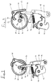
- a door lock 10 is shown schematically, for example Use in the automotive sector for doors, flaps or hoods finds.
- the door lock 10 has a rotary latch Lock latch 12, which has a locking pin arranged on the body side (not shown) locked in their closed position. In this locking position is the lock latch 12 with a locking lug 14 against a catch 16 locked on a pawl 18 which is pivotable about an axis of rotation 20 is stored.
- tension spring 22 is provided, which the lock latch 12 in Direction of their open position against the detent 16 and the pawl 18th to support the locking of the lock latch 12 against a pressure flank 24 preloaded on the lock latch 12.
- the pawl 18 and the Lock latch 12 are one possible omission, for example Locking position between the lock latch 12 and the pawl 18 for Simplified improvement of clarity.
- the door lock 10 also via an opening aid 26.
- This has a drive element 28, which is driven by an electric drive motor (not shown) is, for example, via a worm in a worm gear molded external toothing 30 engages on the drive element 28.
- the drive element is mounted so as to be rotatable about an axis of rotation 32 which is also rotatably mounted a drive plate 34.
- the Driving plate 34 can be rotated relative to drive element 28, the relative twist between these two elements against the force of a compression spring 36 takes place.
- the compression spring 36 is arranged in a spring channel 38 which is open on one side, the with respect to the viewing direction in Figure 1 at the bottom of the Driving plate 34 is formed.
- the spring channel 38 extends over an angular range of approx. 90 ° and is defined by two lateral quarter-circular walls 40 and a rear wall 42 are formed.
- the drive element 28 acts on the free via a spring stop 46 End of the compression spring 36, which creates the required moments on the Drive plate 34 are transferable.
- a second stop 47 am Drive element 28 limits the relative rotatability between the Drive element 28 and the drive plate 34 against the drive direction, to undefined relative positions between these two Elements to avoid.
- the door lock 10 has a pivoted Block lever 48, which has a stop 50 on a first lever arm 52 and has a second lever arm 53 which is connected to the pawl 18th cooperates.
- the door lock 10 according to FIG. 1 is in the locked rest position, the driver pin 44 outside the Engagement area of the pawl 18 and the block lever 48 is.
- the Compression spring 36 is maximally relaxed, but it is in one prestressed state.
- the relative mobility between the drive plate 34 and the Drive element 28 ensures that the driving pin 44 also at a failure of the electric drive motor not the lever arm 54 Block pawl 18 or the first lever arm 52 of the block lever 48 can.
- the door lock 10 can have further functions, for example an automatic closing aid for the door, which can be implemented in the usual way can.
- the door lock can also be used outside the motor vehicle sector is easily conceivable.
Landscapes
- Lock And Its Accessories (AREA)
Abstract
Description
- Figur 1
- ein schematisches Funktionsschaubild eines Türschlosses in der geschlossenen Ruhestellung;
- Figur 2
- das Türschloß gemäß Figur 1 zu Beginn des Öffnungsvorganges;
- Figur 3
- das Türschloß gemäß Figur 1 bei fortgeschrittenem Öffnungsvorgang;
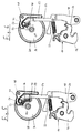
- Figur 4
- das Türschloß kurz nach dem Entriegeln der Schloßfalle;
- Figur 5
- das Türschloß gemäß Figur 1 nach Abschluß des Öffnungsvorgangs vor dem Abschalten des Antriebes;
- Figur 6
- das Türschloß gemäß Figur 1 in der geöffneten Ruhestellung.
Claims (11)
- Türschloß, insbesondere für Türen, Klappen oder Hauben von Kraftfahrzeugen, mit einer Schloßfalle (12), die zwischen einer einen Schließzapfen freigebenden und einer diesen verriegelnden Stellung verschwenkbar ist, einer Sperrklinke (18), die zwischen einer die Schloßfalle (12) arretierenden Schließstellung und einer die Schloßfalle (12) freigebende Stellung beweglich ist, und einem motorisch angetriebenen umlaufenden Mitnehmerbolzen, der bei eingeschaltetem Antrieb auf seiner Bahn die Sperrklinke (18, 54) in ihre die Schloßfalle (12) freigebende Stellung mitnimmt und anschließend gegen einen Anschlag (50) läuft, den die sich in ihrer die Schloßfalle (12) freigebenden Stellung befindliche Sperrklinke (18) in einer den Mitnehmerbolzen (44) blockierenden Lage hält, dadurch gekennzeichnet, daß der Anschlag (50) an einem getrennt von der Sperrklinke (18) gelagerten Blockhebel (48) angeordnet ist, der von der Sperrklinke (18, 54) bei deren Verlagerung in die die Schloßfalle (12) freigebende Stellung in seine Blockierstellung mitnehmbar ist.
- Türschloß nach Anspruch 1, dadurch gekennzeichnet, daß der Antriebsmotor ein Antriebselement (28) antreibt, das in einem bestimmten Winkelbereich gegen die Kraft einer Feder (36) relativ zu einer auf der gleichen Drehachse (32) angeordneten Mitnehmerscheibe (34) verdrehbar ist, an welcher der Mitnehmerbolzen (44) exzentrisch angeordnet ist.
- Türschloß nach Anspruch 2, dadurch gekennzeichnet, daß die Feder (36) vorgespannt ist.
- Türschloß nach Anspruch 2 oder 3, dadurch gekennzeichnet, daß als Feder eine Druckfeder (36) in einem einseitig offenen Federkanal (38) an dem Antriebselement (28) oder der Mitnehmerscheibe (34) angeordnet ist und sich an einem Anschlag (46) an dem jeweils anderen Bauteil (28, 34) abstützt.
- Türschloß nach Anspruch 4, dadurch gekennzeichnet, daß ein zweiter Anschlag (47) mit der Rückseite (42) des Federkanals (36) zusammenwirkt und die relative Verdrehbarkeit zwischen dem Antriebselement (28) und der Mitnehmerscheibe (34) entgegen der Vorspannrichtung der Druckfeder (36) begrenzt.
- Türschloß nach Anspruch 4 oder 5, dadurch gekennzeichnet, daß sich der Federkanal (38) über einen Winkelbereich von ungefähr 90° erstreckt und von zwei seitlichen, kreisbogenförmigen Wandungen (40) begrenzt ist.
- Türschloß nach einem der Ansprüche 2 bis 6, dadurch gekennzeichnet, daß die Feder (36) über einen Drehwinkel von ungefähr 45° vorspannbar ist.
- Türschloß nach einem der vorhergehenden Ansprüche, dadurch gekennzeichnet, daß die Schloßfalle (12) durch eine Feder (22) in Richtung ihrer geöffneten Stellung vorbelastet ist.
- Türschloß nach einem der vorhergehenden Ansprüche, dadurch gekennzeichnet, daß die Sperrklinke (18) durch eine Feder (22) in Richtung ihrer die Schloßfalle (12) arretierenden Stellung vorbelastet ist.
- Türschloß nach Anspruch 8 und 9, dadurch gekennzeichnet, daß eine einzige Feder (22) zwischen der Schloßfalle (12) und der Sperrklinke (18) beide Elemente gleichzeitig vorspannt.
- Türschloß nach einem der vorhergehenden Ansprüche, dadurch gekennzeichnet, daß die Mitnehmerscheibe (34) und/oder das Antriebselement (28) aus Kunststoff gefertigt sind.
Applications Claiming Priority (2)
| Application Number | Priority Date | Filing Date | Title |
|---|---|---|---|
| DE19948052A DE19948052A1 (de) | 1999-10-06 | 1999-10-06 | Öffnungshilfe für Türschlösser |
| DE19948052 | 1999-10-06 |
Publications (2)
| Publication Number | Publication Date |
|---|---|
| EP1091061A2 true EP1091061A2 (de) | 2001-04-11 |
| EP1091061A3 EP1091061A3 (de) | 2002-10-30 |
Family
ID=7924637
Family Applications (1)
| Application Number | Title | Priority Date | Filing Date |
|---|---|---|---|
| EP00120626A Withdrawn EP1091061A3 (de) | 1999-10-06 | 2000-09-21 | Öffnungshilfe für Türschlösser |
Country Status (3)
| Country | Link |
|---|---|
| US (1) | US6390517B1 (de) |
| EP (1) | EP1091061A3 (de) |
| DE (1) | DE19948052A1 (de) |
Cited By (2)
| Publication number | Priority date | Publication date | Assignee | Title |
|---|---|---|---|---|
| WO2003018939A1 (de) * | 2001-08-27 | 2003-03-06 | Kiekert Aktiengesellschaft | Kraftfahrzeugtürverschluss |
| US10995525B2 (en) | 2017-09-19 | 2021-05-04 | Kiekert Ag | Single rotation release gear blocking lever |
Families Citing this family (36)
| Publication number | Priority date | Publication date | Assignee | Title |
|---|---|---|---|---|
| DE19934128A1 (de) * | 1999-07-23 | 2001-01-25 | Kiekert Ag | Kraftfahrzeugtürverschluss |
| JP4474811B2 (ja) * | 2000-11-27 | 2010-06-09 | 株式会社デンソー | ドアロック駆動装置 |
| DE10164829B4 (de) * | 2001-01-02 | 2006-07-13 | Brose Schließsysteme GmbH & Co.KG | Kraftfahrzeug-Türschloss, ausgeführt als Elektroschloss |
| DE10100010B4 (de) * | 2001-01-02 | 2005-05-12 | Brose Schließsysteme GmbH & Co.KG | Kraftfahrzeug-Türschloß, ausgeführt als Elektroschloß, sowie Verfahren zur Montage eines als Elektroschloß ausgeführten Kraftfahrzeug-Türschlosses |
| GB0110456D0 (en) * | 2001-04-28 | 2001-06-20 | Meritor Light Vehicle Sys Ltd | Latch assembly |
| US6679531B2 (en) * | 2001-05-03 | 2004-01-20 | Delphi Technologies, Inc. | Vehicle compartment latch |
| CA2451398A1 (en) * | 2001-07-26 | 2003-02-06 | Grupo Antolin-Ingenieria, S.A. | Rear seat lock for vehicles |
| DE10143366A1 (de) * | 2001-09-04 | 2003-03-20 | Kiekert Ag | Kraftfahrzeugtürverschluss |
| CA2460818C (en) * | 2001-09-19 | 2010-07-20 | Intier Automotive Closures Inc. | Latch with uni-directional power release mechanism |
| CA2469258C (en) * | 2001-12-12 | 2010-11-16 | Intier Automotive Closures Inc. | Snowload lever with two part pawl lever construction |
| DE10214691B4 (de) * | 2002-04-03 | 2013-09-26 | Volkswagen Ag | Verriegelungsvorrichtung |
| DE10312093B4 (de) * | 2002-08-24 | 2007-12-06 | BÖCO Böddecker & Co. GmbH & Co. KG | Drehfallenschloss |
| EP1428959B1 (de) * | 2002-12-11 | 2005-08-10 | Brose Schliesssysteme GmbH & Co. KG | Kraftfahrzeug-Türschloss |
| DE10310766A1 (de) * | 2003-03-12 | 2004-09-23 | Siemens Ag | Vorrichtung zur reversiblen Bewegung eines Schließbügels eines Schlosses sowie Verwendung dieser Vorrichtung |
| DE10331080A1 (de) * | 2003-07-09 | 2005-01-27 | Kiekert Ag | Kraftfahrzeugtürverschluss |
| US8474886B2 (en) * | 2003-07-09 | 2013-07-02 | Kiekert Aktiengesellschaft | Vehicle door latch |
| DE10336049A1 (de) * | 2003-08-01 | 2005-02-17 | Kiekert Ag | Kraftfahrzeugtürverschluss |
| CA2439780C (en) * | 2003-09-08 | 2011-09-20 | Intier Automotive Closures Inc. | Power actuator for automotive closure latch |
| US20070126244A1 (en) * | 2003-09-09 | 2007-06-07 | Intier Automotive Closures Inc. | Power Actuator for Automotive Closure Latch |
| US20050134053A1 (en) * | 2003-12-23 | 2005-06-23 | Honeywell International, Inc. | Storage of actuation energy in automotive door latch |
| DE102004027420A1 (de) * | 2004-06-04 | 2005-12-22 | Brose Schließsysteme GmbH & Co.KG | Motorische Kraftfahrzeugkomponente |
| DE102004033735B4 (de) * | 2004-07-13 | 2006-07-27 | Huf Hülsbeck & Fürst Gmbh & Co. Kg | Vorrichtung zur Betätigung von Schlössern an Türen oder Klappen von Fahrzeugen |
| US7152890B2 (en) * | 2004-09-02 | 2006-12-26 | Kiekert Ag | Power-open motor-vehicle latch |
| EP1746230A1 (de) * | 2005-07-21 | 2007-01-24 | ArvinMeritor Light Vehicle Systems (UK) Ltd | Kraftbetriebene Auslösevorrichtung |
| SE532853C2 (sv) * | 2007-02-23 | 2010-04-20 | Phoniro Ab | Anordning och metod för upplåsning av lås med hjälp av strömövervakning |
| WO2009151929A2 (en) * | 2008-05-27 | 2009-12-17 | Inteva Products Llc. | Vehicle latch |
| DE102008064458C5 (de) * | 2008-12-19 | 2022-08-11 | Adient Luxembourg Holding S.À R.L. | Verriegelungsvorrichtung für einen Fahrzeugsitz, Verriegelungsvorrichtungssystem und Verfahren zur Herstellung einer Verriegelungsvorrichtung |
| EP2531680B1 (de) * | 2010-02-05 | 2018-10-24 | Magna Closures SpA | Fahrzeugverriegelung mit doppelklinkenanordnung |
| US9546503B2 (en) * | 2013-03-06 | 2017-01-17 | Questek Manufacturing Corporation | Electromechanical rotary latch |
| CN206581743U (zh) * | 2017-03-03 | 2017-10-24 | 恩坦华产品有限责任公司 | 用于车辆锁闩致动器机构的弹簧保持组件 |
| DE102017124517A1 (de) * | 2017-10-20 | 2019-04-25 | Kiekert Ag | Kraftfahrzeugschließsystem mit elektrischer Öffnungseinrichtung |
| DE102018109477A1 (de) * | 2018-04-20 | 2019-10-24 | Kiekert Ag | Kraftfahrzeug-Antriebsanordnung |
| DE102018125137A1 (de) * | 2018-10-11 | 2020-04-16 | Kiekert Aktiengesellschaft | Elektromotorische Kraftfahrzeug-Antriebseinheit |
| DE102021102559A1 (de) | 2021-02-04 | 2022-08-04 | Kiekert Aktiengesellschaft | Elektromotorischer Antrieb für kraftfahrzeug-technische Anwendungen |
| DE102021102560A1 (de) * | 2021-02-04 | 2022-08-04 | Kiekert Aktiengesellschaft | Elektromotorischer Antrieb für kraftfahrzeug-technische Anwendungen |
| DE102021132141A1 (de) * | 2021-12-07 | 2023-06-07 | Kiekert Aktiengesellschaft | Kraftfahrzeug-Schloss |
Citations (1)
| Publication number | Priority date | Publication date | Assignee | Title |
|---|---|---|---|---|
| DE19505779A1 (de) | 1995-02-20 | 1996-08-29 | Bocklenberg & Motte Bomoro | Kraftfahrzeug-Klappenschloß, insbesondere Heckklappenschloß |
Family Cites Families (19)
| Publication number | Priority date | Publication date | Assignee | Title |
|---|---|---|---|---|
| US4518181A (en) * | 1982-05-28 | 1985-05-21 | Mitsui Kinzoku Kogyo Kabushiki Kaisha | Locking device |
| JP2707637B2 (ja) * | 1988-09-30 | 1998-02-04 | アイシン精機株式会社 | ラゲージドアロック装置 |
| JPH0828119A (ja) * | 1994-05-13 | 1996-01-30 | Nippondenso Co Ltd | ドアロック駆動装置 |
| DE19508026B4 (de) * | 1995-03-07 | 2005-12-29 | Brose Schließsysteme GmbH & Co.KG | Elektromotorische Betätigungseinheit |
| DE19614123A1 (de) * | 1996-04-11 | 1997-10-16 | Bosch Gmbh Robert | Kraftfahrzeug-Klappenschloß oder -Türschloß |
| DE19614122B4 (de) * | 1996-04-11 | 2006-04-27 | Brose Schließsysteme GmbH & Co.KG | Kraftfahrzeug-Klappenschloß oder -Türschloß |
| DE19650661B4 (de) * | 1996-12-06 | 2007-03-08 | Kiekert Ag | Kraftfahrzeugtürverschluss mit elektrischem Kraftfahrzeugtürschloss |
| DE19702420C5 (de) * | 1997-01-24 | 2009-12-31 | Audi Ag | Steuervorrichtung für einen Verschluß, insbesondere von Kraftfahrzeugtüren |
| DE19725416C1 (de) * | 1997-06-17 | 1999-01-21 | Huf Huelsbeck & Fuerst Gmbh | Drehfallenschloß, insbesondere für Kraftfahrzeuge |
| DE19742798B4 (de) * | 1997-07-18 | 2005-10-27 | Brose Schließsysteme GmbH & Co.KG | Kraftfahrzeug-Türschloß o. dgl. mit Öffnungshilfe und Kindersicherung |
| DE19754216C2 (de) * | 1997-09-15 | 2000-09-14 | Bosch Gmbh Robert | Kraftfahrzeug-Türschließeinrichtung |
| DE19747211C2 (de) * | 1997-10-25 | 2000-02-17 | Bosch Gmbh Robert | Kleine motorische Antriebseinrichtung für ein bewegliches Funktionselement in einem Kraftfahrzeug |
| DE19755695A1 (de) * | 1997-12-16 | 1999-06-17 | Huf Huelsbeck & Fuerst Gmbh | Drehfallenschloß, insbesondere für Fahrzeuge |
| DE29813797U1 (de) * | 1998-02-11 | 1998-10-22 | Mannesmann VDO AG, 60388 Frankfurt | Türschloß mit einer Öffnungshilfe |
| US6000257A (en) * | 1998-03-13 | 1999-12-14 | Ford Global Technologies, Inc. | Electric latch mechanism with an integral auxiliary mechanical release |
| FR2778196B1 (fr) * | 1998-04-30 | 2000-06-23 | Valeo Securite Habitacle | Serrure de porte de vehicule automobile |
| DE19828040B4 (de) * | 1998-06-24 | 2005-05-19 | Siemens Ag | Kraftunterstützte Schließeinrichtung |
| US6076868A (en) * | 1999-02-09 | 2000-06-20 | General Motors Corporation | Vehicle compartment latch |
| DE19944407A1 (de) * | 1999-09-16 | 2001-03-22 | Mannesmann Vdo Ag | Türschloß mit Öffnungshilfe |
-
1999
- 1999-10-06 DE DE19948052A patent/DE19948052A1/de not_active Withdrawn
-
2000
- 2000-09-21 EP EP00120626A patent/EP1091061A3/de not_active Withdrawn
- 2000-10-04 US US09/676,479 patent/US6390517B1/en not_active Expired - Fee Related
Patent Citations (1)
| Publication number | Priority date | Publication date | Assignee | Title |
|---|---|---|---|---|
| DE19505779A1 (de) | 1995-02-20 | 1996-08-29 | Bocklenberg & Motte Bomoro | Kraftfahrzeug-Klappenschloß, insbesondere Heckklappenschloß |
Cited By (2)
| Publication number | Priority date | Publication date | Assignee | Title |
|---|---|---|---|---|
| WO2003018939A1 (de) * | 2001-08-27 | 2003-03-06 | Kiekert Aktiengesellschaft | Kraftfahrzeugtürverschluss |
| US10995525B2 (en) | 2017-09-19 | 2021-05-04 | Kiekert Ag | Single rotation release gear blocking lever |
Also Published As
| Publication number | Publication date |
|---|---|
| DE19948052A1 (de) | 2001-04-12 |
| US6390517B1 (en) | 2002-05-21 |
| EP1091061A3 (de) | 2002-10-30 |
Similar Documents
| Publication | Publication Date | Title |
|---|---|---|
| EP1091061A2 (de) | Öffnungshilfe für Türschlösser | |
| EP2326781B1 (de) | Schlosseinheit mit mehrteiliger sperrklinke und federvorgespannter blockierklinke | |
| EP0722029B1 (de) | Kraftfahrzeug-Türschloss mit rotorischer Zentralverriegelung | |
| DE19841309C2 (de) | Schloß für Klappen, Türen oder dgl. von Fahrzeugen, insbesondere Handschuhfach-Schloß | |
| EP1485558A1 (de) | Schloss, insbesondere für kraftfahrzeugtüren, -klappen od. dgl. | |
| EP3841265B1 (de) | Kraftfahrzeugschloss, insbesondere elektrisch betätigbares kraftfahrzeugschloss | |
| WO2009149686A1 (de) | Schliessvorrichtung mit sperrklinkenfeder | |
| WO2021151423A1 (de) | Elektrisch betätigbares kraftfahrzeugschloss | |
| DE102007060915B4 (de) | Schließvorrichtung mit Endlagensicherung | |
| EP4182529A1 (de) | Kraftfahrzeugschloss | |
| DE102007025309A1 (de) | Verschluss für Fahrzeuge | |
| EP2010739A2 (de) | Kraftfahrzeugtürverschluss | |
| DE102018214355A1 (de) | Schloss für eine Motorhaube eines Fahrzeugs | |
| EP1243725B1 (de) | Schliesseinrichtung mit Zuziehhilfe | |
| EP1085148B1 (de) | Türschloss mit Öffnungshilfe | |
| EP1637675B1 (de) | Drehfallen-Verriegelung für Türen von Fahrzeugen des öffentlichen Personenverkehrs, insbesondere von Schienenfahrzeugen | |
| EP3688257A1 (de) | Kraftfahrzeugschloss | |
| DE102020124240A1 (de) | Aufstellvorrichtung für ein Kraftfahrzeugtürelement | |
| DE10312093A1 (de) | Drehfallenschloss | |
| DE10200551A1 (de) | Kraftfahrzeugschloß-Anordnung | |
| EP3867471B1 (de) | Kraftfahrzeugschloss | |
| EP3899174B1 (de) | Schloss für ein kraftfahrzeug | |
| EP3798393A1 (de) | Notbetätigungsvorrichtung zum manuellen öffnen einer fahrzeugtür | |
| WO2019063040A1 (de) | Kraftfahrzeugschloss | |
| DE102007061442B4 (de) | Verriegelungsvorrichtung mit kraftbetätigtem Schließelement |
Legal Events
| Date | Code | Title | Description |
|---|---|---|---|
| PUAI | Public reference made under article 153(3) epc to a published international application that has entered the european phase |
Free format text: ORIGINAL CODE: 0009012 |
|
| AK | Designated contracting states |
Kind code of ref document: A2 Designated state(s): AT BE CH CY DE DK ES FI FR GB GR IE IT LI LU MC NL PT SE |
|
| AX | Request for extension of the european patent |
Free format text: AL;LT;LV;MK;RO;SI |
|
| RAP1 | Party data changed (applicant data changed or rights of an application transferred) |
Owner name: SIEMENS AKTIENGESELLSCHAFT |
|
| PUAL | Search report despatched |
Free format text: ORIGINAL CODE: 0009013 |
|
| AK | Designated contracting states |
Kind code of ref document: A3 Designated state(s): AT BE CH CY DE DK ES FI FR GB GR IE IT LI LU MC NL PT SE |
|
| AX | Request for extension of the european patent |
Free format text: AL;LT;LV;MK;RO;SI |
|
| 17P | Request for examination filed |
Effective date: 20021118 |
|
| AKX | Designation fees paid |
Designated state(s): DE FR GB IT |
|
| 17Q | First examination report despatched |
Effective date: 20040820 |
|
| STAA | Information on the status of an ep patent application or granted ep patent |
Free format text: STATUS: THE APPLICATION IS DEEMED TO BE WITHDRAWN |
|
| 18D | Application deemed to be withdrawn |
Effective date: 20041231 |