EP1090604A2 - Bracket orthodontique et outil y associé - Google Patents
Bracket orthodontique et outil y associé Download PDFInfo
- Publication number
- EP1090604A2 EP1090604A2 EP00121864A EP00121864A EP1090604A2 EP 1090604 A2 EP1090604 A2 EP 1090604A2 EP 00121864 A EP00121864 A EP 00121864A EP 00121864 A EP00121864 A EP 00121864A EP 1090604 A2 EP1090604 A2 EP 1090604A2
- Authority
- EP
- European Patent Office
- Prior art keywords
- locking member
- bracket
- orthodontic bracket
- base
- arch wire
- Prior art date
- Legal status (The legal status is an assumption and is not a legal conclusion. Google has not performed a legal analysis and makes no representation as to the accuracy of the status listed.)
- Granted
Links
Images


Classifications
-
- A—HUMAN NECESSITIES
- A61—MEDICAL OR VETERINARY SCIENCE; HYGIENE
- A61C—DENTISTRY; APPARATUS OR METHODS FOR ORAL OR DENTAL HYGIENE
- A61C7/00—Orthodontics, i.e. obtaining or maintaining the desired position of teeth, e.g. by straightening, evening, regulating, separating, or by correcting malocclusions
- A61C7/12—Brackets; Arch wires; Combinations thereof; Accessories therefor
- A61C7/28—Securing arch wire to bracket
- A61C7/282—Buccal tubes
-
- A—HUMAN NECESSITIES
- A61—MEDICAL OR VETERINARY SCIENCE; HYGIENE
- A61C—DENTISTRY; APPARATUS OR METHODS FOR ORAL OR DENTAL HYGIENE
- A61C7/00—Orthodontics, i.e. obtaining or maintaining the desired position of teeth, e.g. by straightening, evening, regulating, separating, or by correcting malocclusions
- A61C7/12—Brackets; Arch wires; Combinations thereof; Accessories therefor
- A61C7/28—Securing arch wire to bracket
- A61C7/287—Sliding locks
-
- A—HUMAN NECESSITIES
- A61—MEDICAL OR VETERINARY SCIENCE; HYGIENE
- A61C—DENTISTRY; APPARATUS OR METHODS FOR ORAL OR DENTAL HYGIENE
- A61C7/00—Orthodontics, i.e. obtaining or maintaining the desired position of teeth, e.g. by straightening, evening, regulating, separating, or by correcting malocclusions
- A61C7/12—Brackets; Arch wires; Combinations thereof; Accessories therefor
- A61C7/28—Securing arch wire to bracket
- A61C7/30—Securing arch wire to bracket by resilient means; Dispensers therefor
Definitions
- the present invention relates to an orthodontic bracket, and more particularly to an orthodontic bracket having a shiftable locking member so as to open or close an arch wire slot in a bracket body as well as a tool for an orthodontic bracket.
- orthodontic treatment is effected by fixing small appliances called orthodontic brackets to a patient's teeth.
- the orthodontic brackets are most commonly used by being fixed to the patient's teeth in an appropriate manner so as to correct the misaligned teeth by applying an external force thereto through an arch wire extending between the fixed orthodontic brackets.
- these orthodontic brackets are constructed of a body having small slots and are adhered directly on the labial or lingual sides of the teeth or welded to such as metal bands attached to the teeth by cementing or by some other method.
- an elastic arch wire which is curved so as to conform to a dental arch, is placed in a slot in the bracket, and the tooth can be shifted over time by the restoring force of the elastic arch wire so that the teeth become well aligned.
- a force can be applied to the tooth in a desired direction (in the direction in which the tooth is shifted, rotated, or tilted) by the three-dimensional inclination of the slot formed in the bracket body or by the desired bending of the arch wire.
- the conventional orthodontic bracket has tie wings, and a ligature wire or an elastomeric ligature ring is hooked on the tie wings so as to positively hold the arch wire to prevent the arch wire from coming out of the slot in the bracket.
- the dentition that should be treated isof malocclusion, in which the arch wires are greatly deformed when engaged.
- Orthodontic treatment is done by transmitting the restoring force of the arch wires through brackets to the tooth roots.
- a thin soft round wire is used, and an operation is required to loosen the ligature wire after ligating it such that the round wire freely slides within the slot (on a nonfrictional basis).
- the frictional force cannot be eliminated with the elastomeric ligature ring.
- an end of the ligature wire which has been cut after ligation is accommodated so as to be bent and thrust into a groove under the tie wing.
- Such modes of attachment lead to problems of food residues tending to adhere.
- comparatively large number of measures had to be taken in order to maintain good hygienic conditions inside the teeth.
- the ligature wire causes the trouble of imparting stimuli to the soft tissue of the patient's tongue or cheek as its bent end becomes exposed from below the tie wing. If this ligature wire is cut and reshifted, the patient may swallow the dislocated ligature wire, or the treatment may make no progress. Further, in recent years serious concern has been expressed over various infectious diseases which occur due to bleeding caused by the piercing of the doctor's fingers by the ligature wire.
- this lock-type orthodontic bracket has the structure which does not require the tie wire for ligation, and has a locking member incorporated in the bracket and capable of shifting for opening or closing the slot in the bracket.
- the locking members there are, for example, rotating-type and sliding-type locking members. Since the locking members are capable of shifting, the retention of the arch wire in the slot or disengagement of the arch wire from the slot can be effected very easily.
- the structure is free of a bent portion of the ligature wire and is therefore trim, it is easy to avoid such as the sticking of food and its residue.
- an arch wire 50 in an arch wire slot 85 provided in a bracket body 82 is locked in the slot by a tip portion of a locking member 120 mounted on the bracket body 82.
- a tip portion of the locking member 120 its shift in the loosening direction is restricted by a stop groove 86 continuing to the slot 85, for example.
- the arch wire 50 in the slot 85 is located on the bottom side of the slot, as shown in Fig. 13.
- the arch wire 50 can enter the stop groove 86 and become caught therein, as shown in Fig. 14.
- the arch wire 50 fails to shift smoothly inside the slot, and a hindrance is caused to the orthodontic treatment.
- the invention has been made to overcome the above-described problems, and its object is to provide an orthodontic bracket having a locking member which makes it possible to avoid the situation of the arch wire becoming coming out the slot and entering the stop groove, and which makes the retention of the arch wire more reliable and excels in the operating efficiency.
- the object is to provide an orthodontic bracket excelling in the handling efficiency.
- Another object of the invention is to provide a tool excelling in the efficiency in handling the locking member.
- an orthodontic bracket including a base secured to a tooth surface, a bracket body extending in a substantially perpendicular direction from the base, an arch wire slot which extends in a mesiodistal direction substantially in a center of the bracket body and is open in the front, and a locking member capable of opening or closing the arch wire slot, wherein the locking member is structured in a substantially U-shaped cross-sectional configuration, one side thereof being formed as a base side portion located on a base side and extending along the baser another side thereof being formed as a counter base side portion having substantially the same width as the length of the arch wire slot and extending on an upper side of the slot, the locking member being formed of an elastic member in which a notched portion is provided substantially in a center of the counter base side portion, and that the bracket body has a closing stop groove formed at an open edge portion of the arch wire slot so as to stop a tip of the locking member in a slot closed position as well as an open stop concavity formed at an edge
- the orthodontic bracket in accordance with the invention preferably has the following features.
- the bracket body is a twin bracket having a central groove sandwiched between mesial tie wings and distal tie wings, and the rib is formed over an entire width of the central groove and is formed in such a manner as to be connected to the mesial tie wing and the distal tie wing.
- the bracket body is a single bracket having a tie wing.
- the bracket body is a lingual bracket which is mounted on a lingual side of a tooth.
- a recessed portion is formed in an upper end surface of the rib.
- An engaging end portion formed by a recess or a notch is formed at a rear end portion of the base side portion of the locking member.
- the bracket body has an opening extending therethrough along the mesiodistal direction.
- the bracket body has a projection provided on a side surface of the tie wing where an edge portion of the locking member slides, the projection being capable of abutting against the edge portion, the projection being arranged to be located on an outer side of the edge portion when the slot is closed by the locking member.
- the bracket body is provided with a hook rising and jetting out in the mesiodistal direction of the tie wing of the bracket body.
- the locking member is formed of a single plate material, and is structured such that a portion of the base side portion located close to the base with a substantially longitudinally central portion as a boundary is set at an angle of inclination conforming to the angulation of the bracket, while the counter base side portion on an opposite side away from the side close to the base is set at an angle of inclination which is obtained by correcting an angle corresponding to a bent portion for pressing the arch wire in addition to the angle of inclination of the bracket angulation, a curved portion connecting the base side portion and the counter base side portion forming a portion of a sine curve.
- the bracket body has a rhomboid-type shape, and wherein mesial and distal edge portions of the counter base side portion of the locking member and mesial and distal edge portions of the base side portion, in a top view of the bracket, are formed in parallel along mesial and distal ends of the tie wing of the bracket, and edge portions of the counter base portion extending along the mesiodistal direction are formed to be parallel to the arch wire slot.
- the bracket body has a non-rhomboid-type shape and is of a cut-angulation- type in which, in a plan view of the bracket body, the arch wire slot is inclined with respect to a straight line of the edge portion of the bracket body, and edge portions of the counter base side portion of the locking member extending in the mesiodistal direction are formed to be parallel to the arch wire slot.
- the locking member is formed of a superelastic member.
- the locking member is formed of a beta titanium alloy.
- the locking member is formed of a cobalt-nickel-base alloy (Co-Ni-base alloy) containing chromium (Cr) and molybdenum (Mo).
- Co-Ni-base alloy cobalt-nickel-base alloy
- Cr chromium
- Mo molybdenum
- the locking member is formed of a work-hardening nickel-titanium (Ni-Ti) allay.
- the bracket body has a torque-in-base structure, and the base side portion of the locking member is formed so as to be located in parallel to the base inclined in correspondence with torque.
- the base side portion of the locking member is arranged to slide over the base.
- a tool for an orthodontic bracket in accordance with the invention is characterized by comprising: a fulcrum portion engageable with a portion of the bracket body and an acting portion engageable with a rear end portion of the base side portion, wherein the locking member is operated to slide by using the portion of the bracket body as a fulcrum and an engaging end portion of the rear end portion as a point of application. Consequently, it is possible to attain the above object.
- the fulcrum portion is arranged to be engageable with a recessed portion in an upper end surface of the rib.
- the locking member is structured in a substantially U-shaped cross-sectional configuration, one side thereof being formed as the base side portion located on the base side and extending along the base, another side thereof being formed as the counter base side portion having substantially the same width as the length of the arch wire slot and extending on the upper side of the slot, the locking member being formed of an elastic member in which the notched portion is provided substantially in the center of the counter base side portion.
- the bracket body has the closing stop groove formed at an open edge portion of the arch wire slot so as to stop a tip of the locking member in a slot closed position as well as the open stop concavity formed at an edge portion thereof located away from the stop groove so as to stop the tip of the locking member in a slot open position.
- the rib is formed in a longitudinally central portion of the stop groove in such a manner as to project so as to bury the stop groove in correspondence with the notched portion of the locking member, it is possible to avoid a situation in which the arch wire is disengaged from the slot and enters the stop groove.
- the notched portion of the locking member is correspondingly provided for the rib in the stop groove so as to be fitted to it, the shift and twisting of the tip portion of the locking member in the longitudinal direction of the slot can be effectively suppressed. Namely, with respect to the shift and twisting of the tip portion of the locking member in the longitudinal direction of the slot, such shift can be suppressed by the rib provided in a central region of the stop groove.
- the distance for holding in the mesiodistal direction of the tip of the locking member can be made large without being restricted by the structure of the bracket body.
- the bracket body is a twin bracket having a central groove sandwiched between mesial tie wings and distal tie wings, and the rib is formed over the entire width of the central groove and is formed in such a manner as to be connected to the mesial tie wing and the distal tie wing, the bracket body can be reinforced by this rib.
- the bracket body is a single bracket having tie wings, it is possible to provide an orthodontic bracket which has a locking member and can be used for a rotated tooth or lower jaw anterior teeth having a narrow tooth width and which excels in mountability and operating efficiency.
- the bracket body is a lingual bracket which is mounted on a lingual side of a tooth
- the recessed portion is formed in an upper end surface of the rib, it is possible to insert a tool or the like into the recessed portion, and the recessed portion can be used at the time when the bracket body or the locking member is operated. Further, in a case where the recessed portion has, for instance, a triangular shape, it is effective for-the doctor to discriminate the upper and lower sides in the axial direction of the tooth.
- the bracket body has an opening extending therethrough along the mesiodistal direction, by making use of this opening, treatment can be effectively advanced by attaching an appropriate means for fixing the locking member, by retracting anterior teeth portion by passing an auxiliary wire therethrough, or by using an auxiliary means such as an uprighting spring, a rotation spring, or the like.
- the bracket body has a projection provided on a side surface of the tie wing where an edge portion of the locking member slides, the projection being capable of abutting against the edge portion, the projection being arranged to be located on an outer side of the edge portion when the slot is closed by the locking member.
- bracket body is provided with a hook rising and jetting out in the mesiodistal direction of the tie wing of the bracket body, when the tool is engaged with the bracket body, since the hook juts out so as to escape laterally from the bracket body, no hindrance is caused to the operating efficiency.
- the locking member can be fabricated very easily by such as blanking a plate material.
- the arrangement provided is such that a portion of the base side portion located close to the base by using as a boundary a substantially longitudinally central portion of the portion (leg) extending toward the base side portion in the locking member is set at an angle of inclination conforming; to the angulation of the bracket, while the counter base side portion on an opposite side away from the side close to the base is set at an angle of inclination which is obtained by correcting an angle corresponding to a bent portion for pressing the arch wire in addition to the angle of inclination of the bracket angulation, a curved portion connecting the base side portion and the counter base side portion forming a portion of a sine curve.
- the left and right edge portions of the counter base side portion can be formed to be seen as straight lines.
- the line of each edge portion of the counter base side portion can be utilized in the alignment of the bracket.
- the bracket body has a rhomboid-type shape, and wherein masial and distal edge portions of the counter base side portion of the locking member and mesial and distal edge portions of the base side portion, in a top view of the bracket, are formed in parallel along mesial and distal ends of the tie wing of the bracket, and occlusal edge portions (edge portions close to the base side portion) of the counter base portion and a gingival side edge portion of the notched portion (an edge portion at an innermost portion of the notch) are formed to be parallel to the arch wire slot.
- these edge portions are parallel to the respective sides of a parallelogram of the bracket, so that the respective edge portions of the locking member in the mesiodistal direction and in the axial direction of the tooth can be utilized in the alignment of the bracket.
- the bracket body is of a cut angulation type in which the arch wire slot is inclined with respect to a contour line of a square (non-rhomboid) bracket, and edge portions (tip edge portions, occlusal-side edge portions, and the gingival-side edge portion in the notched portion) of the counter base side portion of the locking member extending in the mesiodistal direction are formed to be parallel to the arch wire slot. Accordingly, in the orthodontic bracket of the cut angulation type, the respective edge portions of the locking member can be utilized in the alignment and orientation.
- the locking member is formed of a superelastic member, i.e., a member having a state in which even if the amount of deformation has increased more than a specific amount, the change in load does not increase and is maintained at a substantially fixed level. Therefore, even if the locking member has undergone relatively large deformation, there is no major change in the load, and it is possible to maintain favorable operating efficiency in the moderate holding down of the arch wire and in the treatment operation.
- the locking member is formed of a beta titanium alloy, since it is possible to enlarge the pressing force (load) relative to the amount of deformation, the slot can be sealed reliably and the arch wire can be pressed positively.
- the locking member is formed of a cobalt-nickel-base alloy (Co-Ni-base alloy) containing chromium (Cr) and molybdenum (Mo), e.g., Elgiloy (trade name) manufactured by Elgin Inc. of the United States or SPRON (trade name) of SII Micro Parts Inc., since relatively large amounts of chromium and molybdenum are contained, such an alloy is able to exhibit high fatigue resistance and corrosion resistance although it has an excellent spring characteristic.
- Co-Ni-base alloy cobalt-nickel-base alloy
- Cr chromium
- Mo molybdenum
- the locking member is formed of a work-hardening nickel-titanium (Ni-Ti) alloy, since the elastic limit in the case of this alloy is also high, the slot can be sealed reliably and the arch wire can be pressed positively.
- the bracket body has a torque-in-base structure, the pressing direction of the counter base side portion of the locking member with respect to the arch wire can be substantially set in a fixed manner. Accordingly, since the arch wire can be maintained in the slot with the orientation and magnitude of a stable pressing force, an effect of accurate treatment can be expected. Namely, even in a case where a plurality of bracket bodies of different forms are used, since the relationship between the arch wire and the locking member can be fixed in any case, it is easy to estimate the treatment effect, and a positive effect of treatment can be expected.
- the base side portion of the locking member is formed so as to be located in parallel to the base inclined in correspondence with torque, and is located close to the bonding base in any case of the torque, the tip portion of the base side portion is not located so as to block the space below the tie wings, so that the amount of food residue stuck can be reduced.
- the base side portion of the locking member is arranged to slide over the base, the base side portion at any position is held by the base. For example, even in a case where the operation of strongly pressing its rear end by a tool is effected, the base side portion is able to open stably without becoming deformed.
- the tool for an orthodontic bracket in accordance with the invention is characterized by comprising: a fulcrum portion engageable with a portion of the bracket body and an acting portion engageable with a rear end portion of the base side portion, wherein the portion of the bracket body is used as a fulcrum and an engaging end portion of the rear end portion is used as a point of application.
- the tool for an orthodontic bracket is arranged such that the fulcrum portion is arranged to be engageable with a recessed portion in an upper end surface of the rib, the portion located in the central region of the bracket body and having sufficient strength can be used as the fulcrum portion for applying the operating force.
- Fig. 1 is an exploded perspective view of a first embodiment of the orthodontic bracket in accordance with the invention.
- Fig. 2 is a plan view of the orthodontic bracket in accordance with the invention.
- Figs. 3A and 3B are a plan view and a side view of a locking member of the orthodontic bracket in accordance with the invention.
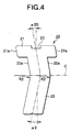
- Fig. 4 is a development view of the locking member of the orthodontic bracket in accordance with the invention.
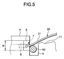
- Fig. 5 is a schematic cross-sectional view for explaining the operation of the locking member and a rib of the orthodontic bracket in accordance with the invention.
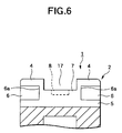
- Fig. 6 is a cross-sectional view of modified example of the portion taken along line X - X in Fig. 1.
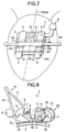
- Fig. 7 is a plan view illustrating a fitted state of the orthodontic bracket in accordance with the invention.
- Fig.8 is a schematic side elevational view for explaining the operation of the orthodontic bracket in accordance with the invention and the operation of a tool for the orthodontic bracket in accordance with a second embodiment.
- Fig. 9 is an exploded perspective view of the orthodontic bracket in accordance with a third embodiment of the invention.
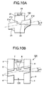
- Figs. 10A and 10B are plan views of the orthodontic bracket in accordance with a fourth embodiment of the invention.
- Fig. 11 is a schematic side elevational view of the orthodontic bracket in accordance with a fifth embodiment of the invention.
- Fig. 12 is a schematic plan view of the orthodontic bracket in accordance with a sixth embodiment of the invention.
- An orthodontic bracket 1 in accordance with the first embodiment shown in Figs. 1 and 2 is a twin bracket having a central groove 17 enclosed by mesial tie wings 4 and distal tie wings 4.
- This bracket 1 is provided with a base 3 secured to a tooth surface, a bracket body 2 extending in a substantially perpendicular direction from the base, and an arch wire slot 5 which extends in a mesiodistal direction substantially in the center of the bracket body 2 and is open in the front.
- the bracket 1 is provided with a locking member 20 capable of opening or closing the arch wire slot 5.
- this locking member 20 is structured in a substantially U-shaped cross-sectional configuration, and one side thereof is formed as a base side portion 22 (a portion located on the lingual side) located on the base side and extending along the base, while the other side thereof is formed as a counter base side portion 21 having substantially the same width as the length of the arch wire slot 5 and extending on the upper side of the slot.
- the locking member 20 is formed of an elastic member in which a notched portion 23 is provided substantially in the center of a tip edge portion of the counter base side portion 21 (a portion located on the labial side).
- a stop groove 6 for stopping a tip of the locking member 20 at a slot closed position is formed in the bracket body at an open edge portion of the arch wire slot 5. Further, an open stop concavity 11 for stopping the tip of the locking member 20 in a slot open position is formed at an edge portion thereof located away from the stop groove 6. A rib 7 projecting to bury the stop groove 6 in correspondence with the notched potion 23 is formed in a longitudinally central portion of the stop groove 6.
- a recessed portion 8 of, for instance, a triangular shape is formed on an upper end surface of the rib 7.
- an opening 14 extending along the arch wire slot 5 (in the mesiodistal direction) is penetratingly formed in the bracket body 2. This opening 14 can be used by allowing a ligating member to be passed therethrough when the locking member 20 is to be fixed more firmly.
- the bracket body 2 is provided with a pair of projections 13 at positions corresponding to both side edge portions of a curved portion of the locking member 20. These projections 13 project to such an extent that they can abut against the side curved portion between the locking member 20 and 21 both edge portions 22a of the curved portion with appropriate pressure.
- the arrangement provided is such that when the locking member 20 has closed the arch wire slot 5, these projections 13 are located on the outer sides of both side edge portions of the curved portion.
- these projections 13 hold down the base side portion 22, thereby suppressing the shift of the locking member 20 in the opening direction.
- the locking member 20 is capable of sliding smoothly on the bracket body 2 so as to open or close the arch wire slot 5. Then, since the rib 7 corresponding to the notched portion 23 in the locking member 20 is formed in the longitudinally central portion of the stop groove 6, even if the height W of the stop groove 6 is formed to be larger than the diameter of an arch wire 50, it is possible to prevent a situation in which the arch wire 50 enters the stop groove 6 when the arch wire 50 is urged so as to be lifted up from the bottom of the slot 5, as shown in Fig. 5.
- the counter base side portion 21 can be held firmly, so that it is possible to prevent the deviation of the counter base side portion 21 in the longitudinal direction of the slot, and the twisting of the counter base side portion 21. Further, since the tip portion of the counter base side portion 21 is stopped by the stop groove 6, the locking member 20 does not open unintentionally toward the labial side.
- the form shown in Figs. 5 and 6 shows a structure different from that of the form shown in Figs. 2 and 3. Namely, in the form shown in Figs 5 and 6, the height of the stop groove 6 is set to be larger than the height of the rib 7. Furthermore, as shown in Fig. 6, the width of the stop groove 6 in the mesiodistal direction is set to be smaller than the width of the tie wing 4, and a side wall 6a of the stop groove 6 is connected to the tie wings 4.
- bracket body 2 is provided with a book 9 whose proximal portion 10 projecting out in the lateral direction (toward the distal side) from the body 2. If this arrangement is provided, for example, when a tool 70 (see Fig. 8) is engaged with the bracket body 2 as will be described later, no hindrance is caused to the operating efficiency.
- the locking member 20 in a case where the locking member 20 is formed of a superelastic member such as a nickel-titanium alloy, even if the locking member has been deformed relatively greatly, there is no large variation of the load, and the arch wire can be pressed down moderately under the superelasticity. Additionally, favorable operating efficiency in the treatment operation can be maintained. For example, wires ranging from a narrow round wire to a full-sized square wire can be pressed into the slot with a virtually equivalent load, and three-dimensional control becomes possible starting from an early period of treatment with an optimum force in the living body. In addition to the restoring force of the wire, the correcting force is also produced by the force with which the locking member presses down the arch wire, and treatment of higher dimensionality becomes possible.
- a superelastic member such as a nickel-titanium alloy
- the locking member 20 is formed of a beta titanium alloy, a Co-Ni-base alloy of high Cr and high Mo, or a work-hardening Ni-Ti alloy, it is possible to enlarge the pressing force (load) relative to the amount of deformation, so that the slot can be sealed reliably and the arch wire can be pressed positively.
- the locking member 20 is formed of a ⁇ titanium alloy, a Co-Ni-base alloy of high Cr and high Mo, or a work-hardening Ni-Ti alloy, although the locking member 20 does not exhibit the property of superelasticity such as that of the nickel-titanium alloy, since the narrow round wire is not pressed down, a totally friction free state is obtained, thereby attaining efficient shift of the tooth.
- Co-Ni-base alloy of high Cr and high Mo it is possible to use one which contains, for example, approx. 39.25 wt.% of cobalt, 15.70 wt.% of nickel, 19.95 wt.% of chromium and the balance essentially consisting of iron and the like.
- the locking member 20 of the orthodontic bracket 1 in this embodiment can be formed by using a single substantially T or Y-shaped plate as its raw material.
- a single substantially T or Y-shaped plate as its raw material.
- an unillustrated plate material is formed into a substantially T or Y-shaped configuration by blanking or the like, and is then formed by bending as described below.
- a portion of the base side portion 22 located close to the base with the substantially longitudinally central portion as the boundary is set at an angle of inclination ⁇ 2 (an angle of 10 degrees or thereabouts) conforming to the angulation of the bracket, while the counter base side portion 21 on the opposite side away from the side close to the base is set at an angle of inclination ⁇ 20 (8 degrees or thereabouts) which is obtained by correcting an angle corresponding to a bent portion for pressing the arch wire in addition to the angle of inclination (10 degrees) of the bracket angulation.
- a curved portion connecting the base side portion 22 and the counter base side portion 21 forms a portion of a sine curve.
- the line of the aforementioned edge portion 22a can be made to conform with the facial axis of the clinical crown (FACC) in cooperation with the mesial and distal side surfaces of the bracket body 2 and the central groove 17 , thereby facilitating the alignment of the bracket.
- left and right edge portions 21a of the counter base portion 21, which is the T or Y-shape head portion in the substantially T or Y-shaped configuration of the locking member 20, and the left and right edge portions 22a of the curved portion, in a top view of the bracket, are formed in parallel along mesial and distal ends of the bracket body flange 2a .
- the locking member 20 can be mounted such that, as a rough criterion, edge portions of the counter base portion 21 extending along the mesiodistal direction become parallel to the occlusal surface or the arch wire line.
- the tool 70 for an orthodontic bracket in this embodiment is not particularly limited to the illustrated form insofar as a first arm portion 71 and a second arm portion 72 are arranged to be appropriately continuous as shown in Fig. 8, and it is possible to adopt various forms.
- the tool 70 for an orthodontic bracket includes the first arm portion 71 which is a fulcrum portion for engagement with the bracket body 2 (in this embodiment, the recessed portion 8 in the upper end surface of the rib 7 provided on the bracket body 2), and the second arm portion 72 which serves as an acting portion for engagement with the engaging end portion 24 (e.g., a notched portion, a recessed portion, a projection, or the like) formed at the rear end portion of the base side portion 22 in the locking member 20.
- the first arm portion 71 which is a fulcrum portion for engagement with the bracket body 2 (in this embodiment, the recessed portion 8 in the upper end surface of the rib 7 provided on the bracket body 2)
- the second arm portion 72 which serves as an acting portion for engagement with the engaging end portion 24 (e.g., a notched portion, a recessed portion, a projection, or the like) formed at the rear end portion of the base side portion 22 in the locking member 20.
- the tool 70 for an orthodontic bracket is structured as described above, by using the recessed portion 8 in the upper end surface of the rib 7 as the fulcrum and the engaging end portion 24 at the rear end portion as the point of application, by pushing the engaging end portion 24 in the X direction as in the illustrated case it is possible to shift the entire locking member 20 in the X direction, thereby effecting the opening operation of the arch wire slot 5. Consequently, the locking member 20 is held in a stopped state as its counter base portion 21 is located in such a manner as to be fitted in the open stop concavity 911.
- the closing operation of the locking member 20 (the operation in a direction opposite to the X direction) can be effected by pushing the curved portion in a direction opposite to the X direction. It should be noted that, in this pressing operation, the completion of the closing operation of the locking member 20 can be recognized by the clicking operation when the left and right edge portions 22a of the curved portion ride over the projections 13 in a terminating stage of the pressing operation.
- An orthodontic bracket 91 in accordance with the third embodiment shown in Fig. 9 is a single bracket in which a bracket body 92 has a pair of tie wings 94, and this bracket 91 is consisting of a base 93 secured to a tooth surface, a bracket body 92 extending in a substantially perpendicular direction from the base 93 and an arch wire slot 95 which extends in the mesiodistal direction substantially in the center of the bracket body 92 and is open in the front.
- the bracket 91 is provided with a locking member 920 capable of opening or closing the arch wire slot 95.
- This locking member 920 has on one side thereof a base side portion 922 located on the base side and extending along the base, and on the other side thereof a counter base side portion 921 having substantially the same width as the length of the arch wire slot 95 and extending on the upper side of the slot.
- the locking member 920 has in its curved portion a hole from which the tie wing is exposed during the closing of the slot.
- the locking member 920 is formed of an elastic member in which a notched portion 923 is provided substantially in the center of a tip edge portion of the counter base side portion 921 (a portion located on the labial side).
- a stop groove 96 for stopping a tip of the locking member 920 at a slot closed position is formed in the bracket body 92 at an open edge portion of the arch wire slot 95. Further, an open stop concavity 911 for stopping the tip of the locking member 920 in the slot open position is formed at an edge portion thereof located away from the stop groove 96. A rib 97 projecting to bury the stop groove 96 in correspondence with the notched potion 923 is formed in a longitudinally central portion of the stop groove 96.
- projections 913 are respectively provided on both mesial and distal side surfaces 912 of one tie wing 94. These projections 913 project to such an extent that they can abut against the curved portion of the leg of the locking member 920 with appropriate pressure. Accordingly, when the locking member 920 has closed the arch wire slot 95, these projections 913 are located on the outer sides of locking member 920. Consequently, even when an unexpected external force has been applied in the oral cavity, these projections 913 suppress the shift of the locking member 920 in the opening direction.
- the bracket body 2 is of a cut-angulation type in which, in a plan view, the arch wire slot 5 is inclined ( ⁇ 3) with respect to a substantially square contour of the bracket.
- a pair of tip edge portions 21d of the counter base side portion 21 of the locking member 120, 21d, and an innermost edge portion 21c of the notched portion 23 become parallel to the arch wire slot 5.
- the leg of the locking member 120 is not provided with an inclination such as ⁇ 2 and a20 (see Fig. 4) and a curve such as R2 and is straight, but the T or Y-shape head portion (the counter base side portion) is inclined by an angle of ⁇ 3.
- a bracket body 201 in this embodiment is similar to that of the first embodiment except that it has a torque-in-base structure, and a description thereof except for the characteristic portion of this embodiment will be omitted, as necessary.
- the orthodontic bracket 201 in this embodiment has the so-called torque-in-base structure in which the base 3 is inclined with respect to the upper structure of the bracket body 2 (i.e., a structure in which when the side walls of the arch wire slot 5 are parallel to the occlusal surface, the base 3 is inclined by a crown inclination angle of ⁇ 4 at a point FA (see Fig. 11)).
- This torque-in-base structure is not a structure in which the arch wire slot 5 is formed in an inclined manner, the pressing direction (in the F direction) of the tip portion of the locking member 20 with respect to a square arch wire 60 becomes stabilized.
- the locking member 20 has an opening angle between the base side portion 22 and the counter base side portion 21. Further, the distance between the base side portion 22 and the counter base side portion 21 (or the size of R1) changes in correspondence with the height of the bracket corresponding to the in/out of the dentition.
- the direction of the load for pressing the square arch wire 60 into the slot becomes stabilized. As a result, it is possible to maintain a stable pressing force, so that an effect of accurate treatment can be expected.
- the base side portion of the locking, member is formed in such a manner as to be located in parallel to the base inclined in correspondence with the torque (with an inclination angle of ⁇ 4), and is close to the bonding base in any case of the torque. Accordingly, the tip portion of the base side portion is not located so as to block the space below the tie wings, so that the amount of food residue stuck can be reduced, thereby making it possible to maintain oral hygiene in a favorable state.
- the base side portion of the locking member is arranged to shift over the bonding base, the base side portion in any position is held by the base. Even in a case where the operation of strongly pressing its rear end by a tool is effected, the base side portion is able to open stably without becoming deformed.
- bracket body 301 in this embodiment is similar to that of the first embodiment except for the shape of the tie wings, and a description thereof except for the characteristic portion of this embodiment will be omitted, as necessary.
- an end face 4a on the arch wire slot side is formed in a tapered shape (or in a substantially conical shape or a chamfered shape).
- a substantially conical shape or a chamfered shape it is possible to avoid breakage or the like of the tip portion of the tie wing 4 during, for example, the replacement operation of the arch wire or the operation of the locking member 20.
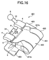
- Fig. 16 shows, for example, a double tube 401 weldable to an orthodontic band, which is provided with a cylindrical tube 450 in the occlusal side.
- This double tube 401 has a welding flange as a base portion.
- the cylindrical tube 450 has a concavity portion 451 so that the lock member 420 is secured to the position on the cylindrical tube 450 when the lock member 420 is retained to the stop groove 6.
- both edge portions 421b, 421b is formed to be curved.
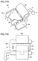
- Figs. 17A and 17B show, for example, a triple tube 501 having a cylindrical tube 550 in the gingival side.
- the triple tube has a welding flange 503 as a base portion.
- a cover member 504 is provided on the bottom of the triple tube 501 so as to secure the lock member 520.
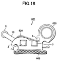
- Fig. 18 shows, for example, a bondable type triple tube 601 having a cylindrical tube 650 provided at the occlusal side, which is directly bonded to the surface of a tooth.
- This triple tube 601 has a bonding base 603 as a base portion.
- the seventh to ninth embodiments are directed to a convertible buccal tube, which is a bracket mainly used for a first molar of upper and lower jaws.
- a convertible cap is initially fixed while it covers the arch wire slot 5 by means of brazing or the like so as to form an angular tube.
- second molars erupt with the growth of a patient
- second molar tubes are attached to them to be uncollege teeth so that they are brought into the teeth arrangement arch to be treated.
- the convertible cap of the tube bracket of the first molar is peeled off, and it is converted to a general bracket, the distal end of the arch wire can be inserted into a second molar tube.
- the peeling operation of the convertible cap in the mouth should be done carefully, and it is difficult to ligate the arch wire to the group of molars.
- the lock member has the function of the distal end tube bracket of the upper and lower teeth arrangement in place of the convertible cap.
- This structure needs no ligature operation and has no convertible cap to be peeled off.
- anterior teeth are retracted by a closing loop provided on the arch wire, it is necessary to be bent to prevent the distal end of the arch wire from pulling off from the arch wire bracket.
- it is necessary to do a difficulty of the conventional tube bracket having the convertible cap that is, the arch wire should be bent at the deep portion of the mouth after insertion, or it is pulled off after straightening.
Priority Applications (1)
| Application Number | Priority Date | Filing Date | Title |
|---|---|---|---|
| DE20023861U DE20023861U1 (de) | 1999-10-08 | 2000-10-06 | Kieferorthopädische Zahnspange und zugehöriges Werkzeug |
Applications Claiming Priority (8)
| Application Number | Priority Date | Filing Date | Title |
|---|---|---|---|
| JP28878599A JP4444410B2 (ja) | 1999-10-08 | 1999-10-08 | 歯列矯正ブラケットおよび歯列矯正ブラケット用ツール |
| JP28878599 | 1999-10-08 | ||
| JP2000010697 | 2000-04-24 | ||
| JP2000010697 | 2000-04-24 | ||
| JP2000010696 | 2000-04-24 | ||
| JP2000010695 | 2000-04-24 | ||
| JP2000010696 | 2000-04-24 | ||
| JP2000010695 | 2000-04-24 |
Publications (3)
| Publication Number | Publication Date |
|---|---|
| EP1090604A2 true EP1090604A2 (fr) | 2001-04-11 |
| EP1090604A3 EP1090604A3 (fr) | 2002-10-16 |
| EP1090604B1 EP1090604B1 (fr) | 2007-07-04 |
Family
ID=27479493
Family Applications (1)
| Application Number | Title | Priority Date | Filing Date |
|---|---|---|---|
| EP00121864A Expired - Lifetime EP1090604B1 (fr) | 1999-10-08 | 2000-10-06 | Bracket orthodontique et outil y associé |
Country Status (6)
| Country | Link |
|---|---|
| US (1) | US6368105B1 (fr) |
| EP (1) | EP1090604B1 (fr) |
| JP (1) | JP4444410B2 (fr) |
| AT (1) | ATE366088T1 (fr) |
| DE (2) | DE60035392T2 (fr) |
| ES (1) | ES2288826T3 (fr) |
Cited By (13)
| Publication number | Priority date | Publication date | Assignee | Title |
|---|---|---|---|---|
| EP1236442A1 (fr) * | 2001-02-28 | 2002-09-04 | Tomy Incorporated | Bracket orthodontique |
| EP1287789A3 (fr) * | 2001-08-24 | 2003-09-17 | Tomy Incorporated | Bague orthodontique |
| WO2004041109A3 (fr) * | 2002-11-04 | 2004-08-26 | 3M Innovative Properties Co | Appareil orthodontique avec verrou de retenue d'arc resistant a la fatigue |
| EP1539017A1 (fr) * | 2002-03-25 | 2005-06-15 | Tp Orthodontics, Inc. | Bracket orthodontique |
| WO2005104982A1 (fr) * | 2004-04-28 | 2005-11-10 | Christoph Von Mandach | Console orthodontique |
| WO2010083491A1 (fr) | 2009-01-16 | 2010-07-22 | Ormco Corporation | Brackets orthodontiques et procédé de correction de dents mal positionnées |
| US7993132B2 (en) | 2002-12-09 | 2011-08-09 | Tomy Incorporated | Orthodontic bracket and clip release tool |
| WO2012107326A1 (fr) * | 2011-02-11 | 2012-08-16 | Christoph Von Mandach | Bracket orthodontique autoligaturant |
| CN103519909A (zh) * | 2013-10-11 | 2014-01-22 | 王光良 | 一种牙齿矫治托槽 |
| EP2705807A1 (fr) | 2012-09-06 | 2014-03-12 | Dental Morelli Ltda. | Mécanisme introduit dans une fixation avec crêtes curvilignes |
| CN104188728A (zh) * | 2007-06-28 | 2014-12-10 | 奥姆科公司 | 自锁正畸托槽及配置其的装置 |
| US10751150B2 (en) | 2005-01-11 | 2020-08-25 | Ormco Corporation | Self-ligating orthodontic bracket |
| CN113231532A (zh) * | 2021-06-09 | 2021-08-10 | 东风柳州汽车有限公司 | 一种冲压分切方法及冲压模具 |
Families Citing this family (63)
| Publication number | Priority date | Publication date | Assignee | Title |
|---|---|---|---|---|
| JP4444410B2 (ja) | 1999-10-08 | 2010-03-31 | トミー株式会社 | 歯列矯正ブラケットおよび歯列矯正ブラケット用ツール |
| US6902396B2 (en) * | 2001-10-16 | 2005-06-07 | George Kyritsis | Orthodontic bracket and positioning system |
| US20040072119A1 (en) * | 2002-06-21 | 2004-04-15 | Orthoarm, Inc. | Self-ligating orthodontic bracket |
| US7959437B2 (en) | 2002-10-29 | 2011-06-14 | Rmo, Inc. | Orthodontic appliance with encoded information formed in the base |
| US7695277B1 (en) * | 2004-10-28 | 2010-04-13 | Rmo, Inc. | Orthodontic bracket with frangible cover mechanism |
| JP4233949B2 (ja) * | 2002-12-09 | 2009-03-04 | トミー株式会社 | 歯列矯正ブラケットおよびグリップ開放ツール |
| US7186114B2 (en) * | 2004-03-30 | 2007-03-06 | Navarro Carlos F | Self-ligating lingual orthodontic bracket |
| WO2006048472A1 (fr) * | 2004-10-29 | 2006-05-11 | Euroortodoncia, S.L. | Bracket a auto-ligaturage comportant des pattes laterales |
| WO2006094403A1 (fr) | 2005-03-10 | 2006-09-14 | Ceramic Sciences, Inc. | Bracket orthodontique auto-ligaturant |
| US20060228662A1 (en) * | 2005-04-08 | 2006-10-12 | Lokar Robert R | Low profile self-ligating bracket assembly and method of use |
| US20060263737A1 (en) * | 2005-05-20 | 2006-11-23 | Ormco Corporation | Orthodontic brackets and appliances and methods of making and using orthodontic brackets |
| US20070213813A1 (en) | 2005-12-22 | 2007-09-13 | Symetis Sa | Stent-valves for valve replacement and associated methods and systems for surgery |
| US20080160474A1 (en) * | 2006-03-31 | 2008-07-03 | Rmo, Inc. | Orthodontic Bracket With Lined Archwire Slot and Slot Cover |
| US20090155734A1 (en) * | 2006-04-19 | 2009-06-18 | Damon Dwight H | Orthodontic bracket |
| US7704072B2 (en) | 2006-04-19 | 2010-04-27 | Ormco Corporation | Orthodontic bracket |
| DE102006027130B4 (de) * | 2006-06-02 | 2012-04-26 | Bernhard Förster Gmbh | Selbstligierendes Bracket und dessen Verwendung für die Orthodontie |
| US8979528B2 (en) | 2006-09-07 | 2015-03-17 | Rmo, Inc. | Customized orthodontic appliance method and system |
| US9554875B2 (en) | 2006-09-07 | 2017-01-31 | Rmo, Inc. | Method for producing a customized orthodontic appliance |
| WO2008031060A2 (fr) | 2006-09-07 | 2008-03-13 | Rmo, Inc. | Tube buccal à frottement réduit et procédé d'utilisation |
| KR100805752B1 (ko) * | 2006-09-08 | 2008-02-21 | 김옥경 | 치아 교정기 |
| US8469704B2 (en) * | 2007-06-28 | 2013-06-25 | Ormco Corporation | Self-ligating orthodontic bracket and devices for deploying same |
| EP2008611A1 (fr) * | 2007-06-28 | 2008-12-31 | Ormco Corporation | Outils à main orthodontiques pour une utilisation avec un support orthodontique à ligature automatique, procédés pour l'utilisation de tels outils à main orthodontiques et supports orthodontiques à ligature automatique et systèmes de supports orthodontiques |
| WO2009067849A1 (fr) * | 2007-11-28 | 2009-06-04 | Zhichun Song | Dispositif orthodontique |
| EP2266495A1 (fr) | 2008-03-18 | 2010-12-29 | Dentsply-Sankin K.K. | Appareil orthodontique |
| JP5770630B2 (ja) | 2008-08-13 | 2015-08-26 | オルムコ コーポレイション | 審美的歯列矯正ブラケット及びその製造方法 |
| US7963768B2 (en) * | 2008-09-05 | 2011-06-21 | Jack Keith Hilliard | Self-ligating orthodontic bracket assembly |
| AU2009238317B2 (en) | 2008-11-14 | 2011-10-06 | Ormco Corporation | Surface treated polycrystalline ceramic orthodontic bracket and method of making same |
| WO2010107567A1 (fr) | 2009-03-16 | 2010-09-23 | Rmo, Inc. | Bracket orthodontique doté d'un canal de fil métallique pour arc, et mécanisme de retenue de fil métallique pour arc |
| US11219507B2 (en) | 2009-03-16 | 2022-01-11 | Orthoamerica Holdings, Llc | Customized orthodontic appliance and method |
| US8636507B2 (en) * | 2009-06-03 | 2014-01-28 | John C. Voudouris | Self-ligating orthodontic bracket |
| US8162660B2 (en) | 2009-11-20 | 2012-04-24 | Robert T Rudman | Rotating clip orthodontic bracket |
| US9345558B2 (en) * | 2010-09-03 | 2016-05-24 | Ormco Corporation | Self-ligating orthodontic bracket and method of making same |
| US10321978B2 (en) | 2010-09-17 | 2019-06-18 | Tomy Incorporated | Orthodontic bracket |
| KR101308816B1 (ko) * | 2010-09-17 | 2013-09-13 | 토미 가부시키가이샤 | 치열 교정용 브라켓 |
| KR101177364B1 (ko) | 2010-11-18 | 2012-08-29 | 휴비트 주식회사 | 자가 결찰방식의 치열교정용 브래킷 |
| WO2012067324A1 (fr) * | 2010-11-18 | 2012-05-24 | 휴비트 주식회사 | Attache auto-fixante destinée à corriger l'alignement des dents |
| FR2969482B1 (fr) | 2010-12-28 | 2013-11-29 | H 32 | Ensemble forme par une attache, un clip et une base pour appareil orthodontique, et appareil orthodontique le comportant |
| FR2969481B1 (fr) | 2010-12-28 | 2013-11-29 | H 32 | Ensemble attache-clip-base avec base pour appareillage orthodontique et appareil orthodontique le comportant. |
| FR2969483B1 (fr) | 2010-12-28 | 2015-07-31 | H 32 | Ensemble forme par une attache auto-ligaturante et un clip elastique, ensemble forme par cette attache, ce clip et une base, et appareil orthodontique le comportant. |
| CN103732176A (zh) * | 2011-02-11 | 2014-04-16 | 欧瑟阿尔穆公司 | 口腔正畸托架 |
| BRPI1100503B1 (pt) | 2011-02-15 | 2022-04-26 | Temistocles Uriarte Zucchi | Braquete interativo/passivo |
| EP2706949B1 (fr) | 2011-05-12 | 2019-11-13 | Rmo, Inc. | Appareil orthodontique ayant des informations codées formées dans la base |
| USD847349S1 (en) | 2011-09-22 | 2019-04-30 | Rmo, Inc. | Orthodontic lock with flange |
| US8568139B2 (en) | 2011-11-23 | 2013-10-29 | Ronald M Roncone | Orthodontic bracket |
| US9585733B2 (en) | 2012-03-28 | 2017-03-07 | Orthoarm, Inc. | Orthodontic bracket with angled, curved shutter |
| EP2644150B1 (fr) | 2012-03-28 | 2019-01-23 | Orthoarm, Inc. | Support actif à ligature automatique |
| JP2015531303A (ja) * | 2012-10-09 | 2015-11-02 | デンツプライ インターナショナル インコーポレーテッド | 自己結紮歯科矯正ブラケット(self−ligatingorthodonticbracket) |
| US9468505B2 (en) | 2013-03-15 | 2016-10-18 | American Orthodontics Corporation | Self-ligating bracket |
| WO2014201460A1 (fr) | 2013-06-14 | 2014-12-18 | Ormco Corporation | Bracket orthodontique autoligaturant avec élément de fermeture rotatif |
| US10111731B2 (en) | 2014-11-18 | 2018-10-30 | American Orthodontics Corporation | Self-ligating bracket |
| CN117814936A (zh) | 2015-06-08 | 2024-04-05 | 美国正畸公司 | 齿列矫正托架绑带的方法 |
| US20170042641A1 (en) * | 2015-08-12 | 2017-02-16 | John C. Voudouris | Low profile self-ligating orthodontic bracket |
| USD797294S1 (en) | 2015-11-12 | 2017-09-12 | American Orthodontics Corporation | Self-ligating bracket |
| JP6313528B2 (ja) | 2015-12-20 | 2018-04-18 | 貞宏 林 | 歯列矯正用ブラケット |
| US11179226B2 (en) * | 2015-12-21 | 2021-11-23 | Premier Orthodontic Designs Lllp | Orthodontic bracket |
| US9770310B2 (en) | 2016-02-25 | 2017-09-26 | Pbd, Patent & Business Development Ag | Orthodontic self-ligating bracket |
| RU2732977C1 (ru) * | 2016-09-21 | 2020-09-25 | Премьер Ортодонтик Дизайнс, Лллп | Ортодонтический брекет |
| KR101988879B1 (ko) * | 2017-08-11 | 2019-09-30 | 김복동 | 치열 교정용 브라켓 |
| KR102140421B1 (ko) * | 2020-02-27 | 2020-07-31 | 주식회사 뷰티스 | 치열 교정용 브라켓 및 이를 포함한 치열 교정 장치 |
| EP4110226A1 (fr) | 2020-02-28 | 2023-01-04 | Hirsch Dynamics Holding AG | Boîtier orthodontique autoligaturant |
| CN111700693A (zh) * | 2020-06-23 | 2020-09-25 | 青岛市口腔医院 | 一种正畸托槽组件及应用所述托槽的正畸智能修复系统 |
| CN213787904U (zh) * | 2020-11-23 | 2021-07-27 | 杭州朋武医疗器械有限公司 | 一种用于牙齿矫正的主动自锁托槽 |
| US20230008397A1 (en) * | 2021-07-07 | 2023-01-12 | World Class Technology Corporation | Tool for use with orthodontic brackets |
Citations (1)
| Publication number | Priority date | Publication date | Assignee | Title |
|---|---|---|---|---|
| US5906486A (en) | 1998-05-07 | 1999-05-25 | Hanson; G. Herbert | Self-ligating orthodontic brackets |
Family Cites Families (10)
| Publication number | Priority date | Publication date | Assignee | Title |
|---|---|---|---|---|
| US2985962A (en) * | 1959-08-07 | 1961-05-30 | Robert L Shiner | Orthodontia appliance tool |
| US4492573A (en) * | 1984-03-27 | 1985-01-08 | Augusta Developments Inc. | Orthodontic bracket |
| DE9016974U1 (fr) * | 1990-12-17 | 1991-03-07 | Hamann, Rainer, 6806 Viernheim, De | |
| DE4407100C2 (de) * | 1994-03-03 | 1997-11-13 | Wolfgang Dr Med Heiser | Bracket für kieferorthopädische Behandlungen |
| US5913680A (en) * | 1994-03-07 | 1999-06-22 | Voudouris; John C. | Orthodontic bracket |
| US5857850A (en) * | 1994-03-07 | 1999-01-12 | Voudouris; John C. | Orthodontic appliance |
| US5586882A (en) * | 1994-07-12 | 1996-12-24 | Hanson; G. Herbert | Self-ligating orthodontic brackets |
| US6071119A (en) * | 1998-12-22 | 2000-06-06 | 3M Innovative Properties Company | Dual mode self-ligating orthodontic bracket |
| US6193508B1 (en) * | 1999-03-25 | 2001-02-27 | 3M Innovative Properties Company | Self-ligating orthodontic bracket with enhanced rotation control |
| JP4444410B2 (ja) | 1999-10-08 | 2010-03-31 | トミー株式会社 | 歯列矯正ブラケットおよび歯列矯正ブラケット用ツール |
-
1999
- 1999-10-08 JP JP28878599A patent/JP4444410B2/ja not_active Expired - Fee Related
-
2000
- 2000-10-06 DE DE60035392T patent/DE60035392T2/de not_active Expired - Lifetime
- 2000-10-06 US US09/684,749 patent/US6368105B1/en not_active Expired - Lifetime
- 2000-10-06 AT AT00121864T patent/ATE366088T1/de not_active IP Right Cessation
- 2000-10-06 ES ES00121864T patent/ES2288826T3/es not_active Expired - Lifetime
- 2000-10-06 EP EP00121864A patent/EP1090604B1/fr not_active Expired - Lifetime
- 2000-10-06 DE DE20023861U patent/DE20023861U1/de not_active Expired - Lifetime
Patent Citations (1)
| Publication number | Priority date | Publication date | Assignee | Title |
|---|---|---|---|---|
| US5906486A (en) | 1998-05-07 | 1999-05-25 | Hanson; G. Herbert | Self-ligating orthodontic brackets |
Cited By (25)
| Publication number | Priority date | Publication date | Assignee | Title |
|---|---|---|---|---|
| US6843651B2 (en) | 2001-02-28 | 2005-01-18 | Tomy Incorporated | Orthodontic bracket |
| EP1236442A1 (fr) * | 2001-02-28 | 2002-09-04 | Tomy Incorporated | Bracket orthodontique |
| EP1287789A3 (fr) * | 2001-08-24 | 2003-09-17 | Tomy Incorporated | Bague orthodontique |
| US6776613B2 (en) | 2001-08-24 | 2004-08-17 | Tomy Incorporated | Orthodontic bracket |
| EP1539017A1 (fr) * | 2002-03-25 | 2005-06-15 | Tp Orthodontics, Inc. | Bracket orthodontique |
| EP1539017A4 (fr) * | 2002-03-25 | 2006-08-09 | Tp Orthodontics Inc | Bracket orthodontique |
| WO2004041109A3 (fr) * | 2002-11-04 | 2004-08-26 | 3M Innovative Properties Co | Appareil orthodontique avec verrou de retenue d'arc resistant a la fatigue |
| US7014460B2 (en) | 2002-11-04 | 2006-03-21 | 3M Innovative Properties Company | Orthodontic appliance with fatigue-resistant archwire retaining latch |
| US7993132B2 (en) | 2002-12-09 | 2011-08-09 | Tomy Incorporated | Orthodontic bracket and clip release tool |
| WO2005104982A1 (fr) * | 2004-04-28 | 2005-11-10 | Christoph Von Mandach | Console orthodontique |
| US7775793B2 (en) | 2004-04-28 | 2010-08-17 | Christoph Von Mandach | Orthodontic bracket |
| US11065088B2 (en) | 2005-01-11 | 2021-07-20 | Ormco Corporation | Self-ligating orthodontic bracket |
| US10751150B2 (en) | 2005-01-11 | 2020-08-25 | Ormco Corporation | Self-ligating orthodontic bracket |
| CN104188728A (zh) * | 2007-06-28 | 2014-12-10 | 奥姆科公司 | 自锁正畸托槽及配置其的装置 |
| CN102348427A (zh) * | 2009-01-16 | 2012-02-08 | 奥姆科公司 | 正畸托槽以及矫正错位牙齿的方法 |
| CN102348427B (zh) * | 2009-01-16 | 2014-11-26 | 奥姆科公司 | 正畸托槽以及矫正错位牙齿的方法 |
| CN104644277A (zh) * | 2009-01-16 | 2015-05-27 | 奥姆科公司 | 正畸托槽以及矫正错位牙齿的方法 |
| EP2387370A4 (fr) * | 2009-01-16 | 2015-08-26 | Ormco Corp | Brackets orthodontiques et procédé de correction de dents mal positionnées |
| US9492247B2 (en) | 2009-01-16 | 2016-11-15 | Ormco Corporation | Orthodontic bracket and method of correcting malpositioned teeth |
| WO2010083491A1 (fr) | 2009-01-16 | 2010-07-22 | Ormco Corporation | Brackets orthodontiques et procédé de correction de dents mal positionnées |
| WO2012107326A1 (fr) * | 2011-02-11 | 2012-08-16 | Christoph Von Mandach | Bracket orthodontique autoligaturant |
| EP2705807A1 (fr) | 2012-09-06 | 2014-03-12 | Dental Morelli Ltda. | Mécanisme introduit dans une fixation avec crêtes curvilignes |
| CN103519909A (zh) * | 2013-10-11 | 2014-01-22 | 王光良 | 一种牙齿矫治托槽 |
| CN103519909B (zh) * | 2013-10-11 | 2016-10-05 | 王光良 | 一种牙齿矫治托槽 |
| CN113231532A (zh) * | 2021-06-09 | 2021-08-10 | 东风柳州汽车有限公司 | 一种冲压分切方法及冲压模具 |
Also Published As
| Publication number | Publication date |
|---|---|
| JP4444410B2 (ja) | 2010-03-31 |
| ES2288826T3 (es) | 2008-02-01 |
| US6368105B1 (en) | 2002-04-09 |
| EP1090604A3 (fr) | 2002-10-16 |
| DE60035392D1 (de) | 2007-08-16 |
| DE60035392T2 (de) | 2007-10-31 |
| JP2001104340A (ja) | 2001-04-17 |
| ATE366088T1 (de) | 2007-07-15 |
| DE20023861U1 (de) | 2006-11-16 |
| EP1090604B1 (fr) | 2007-07-04 |
Similar Documents
| Publication | Publication Date | Title |
|---|---|---|
| EP1090604B1 (fr) | Bracket orthodontique et outil y associé | |
| JP4594434B2 (ja) | 自己解放式ラッチを備えた歯列矯正器具 | |
| US6582226B2 (en) | Orthodontic appliance with self-releasing latch | |
| US6506049B2 (en) | Orthodontic brackets and convertible buccal tubes | |
| US7104791B2 (en) | Orthodontic devices for use with arch wires | |
| CN1997326B (zh) | 正牙托架和夹子 | |
| JP2001104340A5 (fr) | ||
| JP4559525B2 (ja) | 舌側保持溝を備えた歯列矯正器具 | |
| US9498304B2 (en) | Orthodontic attachment module for intra-oral bite correctors | |
| JP2019520153A (ja) | 自己結紮式歯科矯正用ブラケット | |
| JP4406004B2 (ja) | 自己解放式器具を備えた歯列矯正ブレース | |
| US6957957B2 (en) | Molar appliance for orthodontic therapy | |
| JP5038375B2 (ja) | 歯列矯正ブラケット |
Legal Events
| Date | Code | Title | Description |
|---|---|---|---|
| PUAI | Public reference made under article 153(3) epc to a published international application that has entered the european phase |
Free format text: ORIGINAL CODE: 0009012 |
|
| AK | Designated contracting states |
Kind code of ref document: A2 Designated state(s): AT BE CH CY DE DK ES FI FR GB GR IE IT LI LU MC NL PT SE |
|
| AX | Request for extension of the european patent |
Free format text: AL;LT;LV;MK;RO;SI |
|
| PUAL | Search report despatched |
Free format text: ORIGINAL CODE: 0009013 |
|
| AK | Designated contracting states |
Kind code of ref document: A3 Designated state(s): AT BE CH CY DE DK ES FI FR GB GR IE IT LI LU MC NL PT SE |
|
| AX | Request for extension of the european patent |
Free format text: AL;LT;LV;MK;RO;SI |
|
| 17P | Request for examination filed |
Effective date: 20021126 |
|
| AKX | Designation fees paid |
Designated state(s): AT BE CH CY DE DK ES FI FR GB GR IE IT LI LU MC NL PT SE |
|
| GRAP | Despatch of communication of intention to grant a patent |
Free format text: ORIGINAL CODE: EPIDOSNIGR1 |
|
| GRAS | Grant fee paid |
Free format text: ORIGINAL CODE: EPIDOSNIGR3 |
|
| GRAA | (expected) grant |
Free format text: ORIGINAL CODE: 0009210 |
|
| AK | Designated contracting states |
Kind code of ref document: B1 Designated state(s): AT BE CH CY DE DK ES FI FR GB GR IE IT LI LU MC NL PT SE |
|
| REG | Reference to a national code |
Ref country code: GB Ref legal event code: FG4D |
|
| REG | Reference to a national code |
Ref country code: CH Ref legal event code: EP |
|
| REG | Reference to a national code |
Ref country code: IE Ref legal event code: FG4D |
|
| REF | Corresponds to: |
Ref document number: 60035392 Country of ref document: DE Date of ref document: 20070816 Kind code of ref document: P |
|
| REG | Reference to a national code |
Ref country code: SE Ref legal event code: TRGR |
|
| ET | Fr: translation filed | ||
| REG | Reference to a national code |
Ref country code: CH Ref legal event code: PL |
|
| PG25 | Lapsed in a contracting state [announced via postgrant information from national office to epo] |
Ref country code: PT Free format text: LAPSE BECAUSE OF FAILURE TO SUBMIT A TRANSLATION OF THE DESCRIPTION OR TO PAY THE FEE WITHIN THE PRESCRIBED TIME-LIMIT Effective date: 20071204 Ref country code: FI Free format text: LAPSE BECAUSE OF FAILURE TO SUBMIT A TRANSLATION OF THE DESCRIPTION OR TO PAY THE FEE WITHIN THE PRESCRIBED TIME-LIMIT Effective date: 20070704 |
|
| REG | Reference to a national code |
Ref country code: ES Ref legal event code: FG2A Ref document number: 2288826 Country of ref document: ES Kind code of ref document: T3 |
|
| PG25 | Lapsed in a contracting state [announced via postgrant information from national office to epo] |
Ref country code: CH Free format text: LAPSE BECAUSE OF FAILURE TO SUBMIT A TRANSLATION OF THE DESCRIPTION OR TO PAY THE FEE WITHIN THE PRESCRIBED TIME-LIMIT Effective date: 20070704 Ref country code: LI Free format text: LAPSE BECAUSE OF FAILURE TO SUBMIT A TRANSLATION OF THE DESCRIPTION OR TO PAY THE FEE WITHIN THE PRESCRIBED TIME-LIMIT Effective date: 20070704 Ref country code: AT Free format text: LAPSE BECAUSE OF FAILURE TO SUBMIT A TRANSLATION OF THE DESCRIPTION OR TO PAY THE FEE WITHIN THE PRESCRIBED TIME-LIMIT Effective date: 20070704 |
|
| PG25 | Lapsed in a contracting state [announced via postgrant information from national office to epo] |
Ref country code: BE Free format text: LAPSE BECAUSE OF FAILURE TO SUBMIT A TRANSLATION OF THE DESCRIPTION OR TO PAY THE FEE WITHIN THE PRESCRIBED TIME-LIMIT Effective date: 20070704 |
|
| PG25 | Lapsed in a contracting state [announced via postgrant information from national office to epo] |
Ref country code: GR Free format text: LAPSE BECAUSE OF FAILURE TO SUBMIT A TRANSLATION OF THE DESCRIPTION OR TO PAY THE FEE WITHIN THE PRESCRIBED TIME-LIMIT Effective date: 20071005 Ref country code: DK Free format text: LAPSE BECAUSE OF FAILURE TO SUBMIT A TRANSLATION OF THE DESCRIPTION OR TO PAY THE FEE WITHIN THE PRESCRIBED TIME-LIMIT Effective date: 20070704 |
|
| PLBE | No opposition filed within time limit |
Free format text: ORIGINAL CODE: 0009261 |
|
| STAA | Information on the status of an ep patent application or granted ep patent |
Free format text: STATUS: NO OPPOSITION FILED WITHIN TIME LIMIT |
|
| PG25 | Lapsed in a contracting state [announced via postgrant information from national office to epo] |
Ref country code: MC Free format text: LAPSE BECAUSE OF NON-PAYMENT OF DUE FEES Effective date: 20071031 |
|
| 26N | No opposition filed |
Effective date: 20080407 |
|
| PG25 | Lapsed in a contracting state [announced via postgrant information from national office to epo] |
Ref country code: IE Free format text: LAPSE BECAUSE OF NON-PAYMENT OF DUE FEES Effective date: 20071008 |
|
| PG25 | Lapsed in a contracting state [announced via postgrant information from national office to epo] |
Ref country code: CY Free format text: LAPSE BECAUSE OF FAILURE TO SUBMIT A TRANSLATION OF THE DESCRIPTION OR TO PAY THE FEE WITHIN THE PRESCRIBED TIME-LIMIT Effective date: 20070704 |
|
| PG25 | Lapsed in a contracting state [announced via postgrant information from national office to epo] |
Ref country code: LU Free format text: LAPSE BECAUSE OF NON-PAYMENT OF DUE FEES Effective date: 20071006 |
|
| REG | Reference to a national code |
Ref country code: FR Ref legal event code: PLFP Year of fee payment: 17 |
|
| REG | Reference to a national code |
Ref country code: FR Ref legal event code: PLFP Year of fee payment: 18 |
|
| REG | Reference to a national code |
Ref country code: FR Ref legal event code: PLFP Year of fee payment: 19 |
|
| REG | Reference to a national code |
Ref country code: DE Ref legal event code: R081 Ref document number: 60035392 Country of ref document: DE Owner name: TOMY INC., JP Free format text: FORMER OWNER: TOMY INC., FUKUSHIMA, JP Ref country code: DE Ref legal event code: R081 Ref document number: 60035392 Country of ref document: DE Owner name: VOUDOURIS, JOHN C., CA Free format text: FORMER OWNER: TOMY INC., FUKUSHIMA, JP Ref country code: DE Ref legal event code: R082 Ref document number: 60035392 Country of ref document: DE Representative=s name: GRUENECKER PATENT- UND RECHTSANWAELTE PARTG MB, DE |
|
| REG | Reference to a national code |
Ref country code: GB Ref legal event code: 732E Free format text: REGISTERED BETWEEN 20190124 AND 20190130 |
|
| REG | Reference to a national code |
Ref country code: ES Ref legal event code: PC2A Owner name: JOHN C. VOUDOURIS Effective date: 20190219 |
|
| REG | Reference to a national code |
Ref country code: NL Ref legal event code: PD Owner name: JOHN C. VOUDOURIS; CA Free format text: DETAILS ASSIGNMENT: CHANGE OF OWNER(S), ASSIGNMENT; FORMER OWNER NAME: TOMY INCORPORATED Effective date: 20190118 |
|
| PGFP | Annual fee paid to national office [announced via postgrant information from national office to epo] |
Ref country code: NL Payment date: 20190912 Year of fee payment: 20 Ref country code: FR Payment date: 20190913 Year of fee payment: 20 |
|
| PGFP | Annual fee paid to national office [announced via postgrant information from national office to epo] |
Ref country code: DE Payment date: 20190924 Year of fee payment: 20 Ref country code: SE Payment date: 20191010 Year of fee payment: 20 |
|
| PGFP | Annual fee paid to national office [announced via postgrant information from national office to epo] |
Ref country code: ES Payment date: 20191104 Year of fee payment: 20 Ref country code: IT Payment date: 20191009 Year of fee payment: 20 |
|
| PGFP | Annual fee paid to national office [announced via postgrant information from national office to epo] |
Ref country code: GB Payment date: 20191003 Year of fee payment: 20 |
|
| REG | Reference to a national code |
Ref country code: DE Ref legal event code: R071 Ref document number: 60035392 Country of ref document: DE |
|
| REG | Reference to a national code |
Ref country code: NL Ref legal event code: MK Effective date: 20201005 |
|
| REG | Reference to a national code |
Ref country code: GB Ref legal event code: PE20 Expiry date: 20201005 |
|
| PG25 | Lapsed in a contracting state [announced via postgrant information from national office to epo] |
Ref country code: GB Free format text: LAPSE BECAUSE OF EXPIRATION OF PROTECTION Effective date: 20201005 |
|
| REG | Reference to a national code |
Ref country code: ES Ref legal event code: FD2A Effective date: 20210129 |
|
| PG25 | Lapsed in a contracting state [announced via postgrant information from national office to epo] |
Ref country code: ES Free format text: LAPSE BECAUSE OF EXPIRATION OF PROTECTION Effective date: 20201007 |