EP1088658A1 - Kurzfarbwerk - Google Patents
Kurzfarbwerk Download PDFInfo
- Publication number
- EP1088658A1 EP1088658A1 EP00120703A EP00120703A EP1088658A1 EP 1088658 A1 EP1088658 A1 EP 1088658A1 EP 00120703 A EP00120703 A EP 00120703A EP 00120703 A EP00120703 A EP 00120703A EP 1088658 A1 EP1088658 A1 EP 1088658A1
- Authority
- EP
- European Patent Office
- Prior art keywords
- roller
- inking
- center
- unit according
- eccentric
- Prior art date
- Legal status (The legal status is an assumption and is not a legal conclusion. Google has not performed a legal analysis and makes no representation as to the accuracy of the status listed.)
- Granted
Links
- 238000007774 anilox coating Methods 0.000 claims description 37
- 210000003746 feather Anatomy 0.000 description 2
Images


Classifications
-
- B—PERFORMING OPERATIONS; TRANSPORTING
- B41—PRINTING; LINING MACHINES; TYPEWRITERS; STAMPS
- B41F—PRINTING MACHINES OR PRESSES
- B41F31/00—Inking arrangements or devices
- B41F31/30—Arrangements for tripping, lifting, adjusting, or removing inking rollers; Supports, bearings, or forks therefor
- B41F31/304—Arrangements for inking roller bearings, forks or supports
- B41F31/305—Eccentric bearings
Definitions
- the invention relates to a short inking unit of a printing press.
- DE 195 23 378 A1 is a sheet-fed offset rotary printing press for multi-color printing consisting of forme cylinder, rubber cylinder and one with a plurality of controlled Gripper systems provided, central pressure cylinder known, forme cylinder and blanket cylinders have the same diameter and each have at least two pressure surfaces and the number of gripper systems of the printing cylinder not equal to the number of printing areas the forme cylinder and the impression cylinder at least a second one from the forme cylinder and rubber cylinder is assigned to an existing pair of cylinders.
- Each forme cylinder has two printing surfaces and each printing surface of the forme cylinder is its own short inking unit, consisting of inking roller, anilox roller and ink fountain, assigned.
- the inking rollers are alternately on and off the forme cylinder adjustable, only inking the assigned printing area.
- the object of the invention is to create one from an anilox roller, one at a time Printing form cylinder on and off inking roller and an ink fountain existing Short inking unit with high rigidity of the anilox roller bearing.
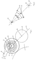
- An inking roller 2 is operatively connected to the printing form cylinder 1 (FIG. 1).
- the inking roller 2 is cyclically actuated by a cycle eccentric 3 to the Printing form cylinder 1 adjustable or removable from this.
- the anilox roller 4 assigned to the inking roller 2 is via a play-free three-ring bearing 5 in the machine frame 6 - indicated in the drawing with slashes - stored.
- the inner ring the three-ring bearing is designed as an eccentric bearing 7 and is on the eccentric bearing Shift lever 8 arranged.
- the eccentric bearing 7 can be rotated by means of the shift lever 8.
- On the shift lever 8 a toggle lever mechanism 9 with a spring 10 is arranged.
- the spring 10 is tensioned via the toggle lever mechanism 9, the force of which acts via the articulation point 11 and the eccentric bearing 7 reinforced on the anilox roller 4.
- On the bale ends of the inking roller 2 and the anilox roller 4 bearer rings are arranged.
- FIG. 2 Another embodiment (FIG. 2) is described below.
- An inking roller 2 is operatively connected to the printing form cylinder 1.
- the inking roller 2 is an operative connection with an ink fountain (not shown) Anilox roller 4 assigned.
- the inking roller 2 is a play-free three-ring bearing 5 in the machine frame 6 - in the Drawing indicated with slashes - stored.
- the inner ring of the three-ring bearing is designed as an eccentric bearing 7 and is on the eccentric bearing a shift lever 8 is arranged.
- the eccentric bearing 7 can be rotated by means of the shift lever 8.
- the rotation is initiated via a shift lever (not shown) on the shift lever 8 arranged cam roller, which with a not shown, arranged on the printing form cylinder Cam is in operative connection.
- the inking roller 2 is turned on and off about a pivot point 12 (Fig. 3).
- the pivot point 12 lies on a straight line 13 which passes through the middle position 14 of the swivel path, which is between the inking roller center 15 when employed and parked inking roller 2, and the anilox roller center 16 leads.
- the pivot point 12 lies on the straight line 13 between the anilox roller center 16 and the center position 14.
- the pivot point 12 on the extension of the straight line 13 behind the middle position 14. Die
- the inking roller swivels around the swivel angle ⁇ , the straight line 13 lies within the swivel angle.
- the third embodiment (Fig. 4) shows a four-ring inking roller.
- An inking roller 2 is operatively connected to the printing form cylinder 1.
- the inking roller 2 is an operative connection with an ink fountain (not shown)
- Anilox roller 4 assigned.
- the anilox roller 4 is mounted in ball bearings, not shown.
- the inking roller 2 is a play-free four-ring bearing 17 in the machine frame 6 - in the drawing with slashes - stored.
- the first inner ring of the four-ring bearing 17 is designed as an eccentric bearing 7 and on the eccentric bearing 7, a shift lever 8 is arranged.
- the eccentric bearing 7 can be rotated by means of the switching lever 8.
- the shift lever 8 is supported by a cam roller 18 on an arranged on the printing form cylinder 1 Clock curve 19 from. Clock springs 20 are operatively connected to the shift lever 8.
- the shift lever 8 is equipped with a locking device 21, with the locking device the clock movement can be blocked.
- the further inner ring of the four-ring bearing 17 is designed as a further eccentric bearing 22 and a further shift lever 23 is arranged on the further eccentric bearing 22.
- a further eccentric bearing 22 For column setting between inking roller 2 and anilox roller 4 - the gap between inking roller and anilox roller must be separated in the event of printing interruptions; is in print mode Ink roller 2 with the anilox roller 4 in operative connection - is the further eccentric bearing 22 can be rotated by means of the further shift lever 23.
- a toggle lever mechanism 9 with a further spring 25 is arranged on the further shift lever 23.
- the toggle lever mechanism 24 is actuated via an actuation mechanism, not shown, for example via a pneumatic cylinder.
- the further spring 25 is tensioned via the toggle lever mechanism 24, the force of which acts via the articulation point 26 and the further eccentric bearing 22 on the inking roller 2.
- the inking roller 2 is supported by the spring force driven against the anilox roller 4; the pressure between the inking roller and anilox roller thus remains constant.
- Bearings are arranged on the bale ends of the inking roller 2 and the anilox roller 4. This arrangement achieves a high degree of rigidity in the roller bearing, the anilox roller being able to be mounted fixed to the frame in simple and inexpensive radial ball bearings.
Landscapes
- Inking, Control Or Cleaning Of Printing Machines (AREA)
- Inks, Pencil-Leads, Or Crayons (AREA)
- Impression-Transfer Materials And Handling Thereof (AREA)
Abstract
Description
- Fig. 1
- Kurzfarbwerk mit dreiringgelagerter Rasterwalze
- Fig. 2
- Kurzfarbwerk mit dreiringgelagerter Farbauftragwalze
- Fig. 3
- Geometrische Anordnung
- Fig. 4
- Kurzfarbwerk mit vierringgelagerter Farbauftragswalze
Auf den Ballenenden der Farbauftragwalze 2 und der Rasterwalze 4 sind Schmitzringe angeordnet.
Durch diese Anordnung wird eine hohe Steifigkeit der Walzenlagerung erreicht, wobei die Rasterwalze in einfachen und kostengünstigen Radialkugellagern gestellfest gelagert werden kann.
- 1
- Druckformzylinder
- 2
- Farbauftragwalze
- 3
- Taktexzenter
- 4
- Rasterwalze
- 5
- Dreiringlager
- 6
- Maschinengestell
- 7
- Exzenterlager
- 8
- Schalthebel
- 9
- Kniehebelgetriebe
- 10
- Feder
- 11
- Anlenkpunkt
- 12
- Schwenkpunkt
- 13
- Gerade
- 14
- Mittelposition
- 15
- Farbauftragwalzenmittelpunkt
- 16
- Rasterwalzenmittelpunkt
- 17
- Vierringlager
- 18
- Kurvenrolle
- 19
- Taktkurve
- 20
- Taktfeder
- 21
- Arretiereinrichtung
- 22
- weiteres Exzenterlager
- 23
- weiterer Schalthebel
- 24
- weitere Feder
- 25
- Anlenkpunkt
Claims (9)
- Kurzfarbwerk mit einer taktweise an einen Druckformzylinder an- und abstellbaren Farbauftragwalze und einer der Farbauftragwalze zugeordneten Rasterwalze einschließlich Farbkasten, dadurch gekennzeichnet, dass die Farbauftragwalze (2) oder die Rasterwalze (4) in einem spielfreien Mehrringlager (5; 17) gelagert ist.
- Kurzfarbwerk nach Anspruch 1, dadurch gekennzeichnet, dass die Rasterwalze (4) beidseitig in je einem spielfreien Dreiringlager (5) mit ein Exzenterlager (7) bildenden exzentrischen Mittelringen im Maschinengestell (6) gelagert, die Exzenterlager (7) über einen kurvengesteuerten Schalthebel (8) zur An- und Abstellung verdrehbar und an dem Schalthebel (8) ein Kniehebelgetriebe (9) mit einer die Rasterwalze (4) im angestellten Zustand gegen die Farbauftragwalze (2) drückenden Feder (10) angeordnet ist.
- Kurzfarbwerk nach Anspruch 1, dadurch gekennzeichnet, dass die Farbauftragwalze (2) beidseitig in je einem spielfreien Dreiringlager (5) mit ein Exzenterlager (7) bildenden exzentrischen Mittelringen im Maschinengestell (6) gelagert, die Exzenterlager (7) über einen Schalthebel (8) zur An- und Abstellung verdrehbar und der Schwenkpunkt (12) der Farbauftragwalze (2) auf der durch den Rasterwalzenmittelpunkt (16) und der Mittelposition (14) des Schwenkweges des Farbauftragwalzenmittelpunktes (15) bei der An- und Abstellung führenden Geraden (13) angeordnet ist.
- Kurzfarbwerk nach Anspruch 3, dadurch gekennzeichnet, dass der Schwenkpunkt (12) zwischen dem Rasterwalzenmittelpunkt (16) und der Mittelposition (14) des Schwenkweges des Farbauftragwalzenmittelpunktes (15) bei der An- und Abstellung angeordnet ist.
- Kurzfarbwerk nach Anspruch 3, dadurch gekennzeichnet, dass der Schwenkpunkt (12) in der Verlängerung der Geraden (13) hinter der Mittelposition (14) des Schwenkweges des Farbauftragwalzenmittelpunktes (15) bei der An- und Abstellung angeordnet ist.
- Kurzfarbwerk nach Anspruch 3, dadurch gekennzeichnet, das die Gerade (13) innerhalb des Schwenkwinkels (γ) angeordnet ist.
- Kurzfarbwerk nach Anspruch 1, dadurch gekennzeichnet, dass die Rasterwalze (4) in Kugellagern gelagert, die Farbauftragwalze (2) beidseitig in je einem spielfreien Vierringlager (17) mit zwei Exzenterlagern (7; 12) bildenden exzentrischen Mittelringen im Maschinengestell (6) gelagert, das Exzenterlager (7) über einen kurvengesteuerten Schalthebel (8) zur An- und Abstellung verdrehbar und das weitere Exzenterlager (22) über einen weiteren Schalthebel (23) zur Spalteinstellung der Farbauftragwalze (2) relativ zur Rasterwalze (4) verdrehbar und an dem weiteren Schalthebel (23) ein Kniehebelgetriebe (9) mit einer die Farbauftragwalze (2) im angestellten Zustand gegen die Rasterwalze (4) drückenden Feder (25) angeordnet ist
- Kurzfarbwerk nach Anspruch 7, dadurch gekennzeichnet, dass der Schalthebel (8) in der ausgehobenen Stellung arretierbar ist.
- Kurzfarbwerk nach Anspruch 2 oder 7, dadurch gekennzeichnet, dass auf beiden Ballenenden von Farbauftragwalze (2) und Rasterwalze (4) Schmitzringe angeordnet sind.
Applications Claiming Priority (6)
| Application Number | Priority Date | Filing Date | Title |
|---|---|---|---|
| DE1999147227 DE19947227A1 (de) | 1999-10-01 | 1999-10-01 | Kurzfarbwerk |
| DE19947224 | 1999-10-01 | ||
| DE1999147220 DE19947220A1 (de) | 1999-10-01 | 1999-10-01 | Kurzfarbwerk |
| DE19947227 | 1999-10-01 | ||
| DE19947220 | 1999-10-01 | ||
| DE1999147224 DE19947224A1 (de) | 1999-10-01 | 1999-10-01 | Kurzfarbwerk |
Publications (2)
| Publication Number | Publication Date |
|---|---|
| EP1088658A1 true EP1088658A1 (de) | 2001-04-04 |
| EP1088658B1 EP1088658B1 (de) | 2005-11-23 |
Family
ID=27219304
Family Applications (1)
| Application Number | Title | Priority Date | Filing Date |
|---|---|---|---|
| EP00120703A Expired - Lifetime EP1088658B1 (de) | 1999-10-01 | 2000-09-22 | Kurzfarbwerk |
Country Status (3)
| Country | Link |
|---|---|
| EP (1) | EP1088658B1 (de) |
| AT (1) | ATE310639T1 (de) |
| DE (1) | DE50011677D1 (de) |
Cited By (4)
| Publication number | Priority date | Publication date | Assignee | Title |
|---|---|---|---|---|
| EP2127871A1 (de) * | 2008-05-29 | 2009-12-02 | Windmöller & Hölscher KG | Farb- oder Druckwerk einer Druckmaschine |
| DE102011119088A1 (de) * | 2011-11-22 | 2013-05-23 | Gallus Druckmaschinen Gmbh | Flexodruckwerk mit Kniehebelsystem |
| CN105517803A (zh) * | 2013-09-09 | 2016-04-20 | 柯尼格及包尔公开股份有限公司 | 用于调整印刷机的导墨的旋转体的方法和装置 |
| CN105517802A (zh) * | 2013-09-09 | 2016-04-20 | 柯尼格及包尔公开股份有限公司 | 用于有价证券印刷的印刷机以及用于更换印版的方法和印刷机的启动 |
Families Citing this family (3)
| Publication number | Priority date | Publication date | Assignee | Title |
|---|---|---|---|---|
| DE102007052761B4 (de) * | 2006-11-20 | 2018-02-22 | Heidelberger Druckmaschinen Ag | Anilox-Druckwerk |
| US8499692B2 (en) | 2006-11-20 | 2013-08-06 | Heidelberger Druckmaschinen Ag | Anilox printing unit and printing press having an anilox printing unit |
| DE102008022633A1 (de) * | 2008-05-08 | 2009-11-12 | Manroland Ag | Filmwalze für ein Farbwerk |
Citations (2)
| Publication number | Priority date | Publication date | Assignee | Title |
|---|---|---|---|---|
| DE9110806U1 (de) * | 1991-08-31 | 1991-10-17 | Heidelberger Druckmaschinen Ag, 6900 Heidelberg | Vorrichtung zum Einstellen von Auftragwalzen am Plattenzylinder von Rotationsdruckmaschinen |
| DE19523378A1 (de) * | 1995-06-30 | 1997-01-02 | Koenig & Bauer Albert Ag | Bogenoffsetrotationsdruckmaschine |
-
2000
- 2000-09-22 AT AT00120703T patent/ATE310639T1/de not_active IP Right Cessation
- 2000-09-22 EP EP00120703A patent/EP1088658B1/de not_active Expired - Lifetime
- 2000-09-22 DE DE50011677T patent/DE50011677D1/de not_active Expired - Lifetime
Patent Citations (2)
| Publication number | Priority date | Publication date | Assignee | Title |
|---|---|---|---|---|
| DE9110806U1 (de) * | 1991-08-31 | 1991-10-17 | Heidelberger Druckmaschinen Ag, 6900 Heidelberg | Vorrichtung zum Einstellen von Auftragwalzen am Plattenzylinder von Rotationsdruckmaschinen |
| DE19523378A1 (de) * | 1995-06-30 | 1997-01-02 | Koenig & Bauer Albert Ag | Bogenoffsetrotationsdruckmaschine |
Cited By (8)
| Publication number | Priority date | Publication date | Assignee | Title |
|---|---|---|---|---|
| EP2127871A1 (de) * | 2008-05-29 | 2009-12-02 | Windmöller & Hölscher KG | Farb- oder Druckwerk einer Druckmaschine |
| DE102011119088A1 (de) * | 2011-11-22 | 2013-05-23 | Gallus Druckmaschinen Gmbh | Flexodruckwerk mit Kniehebelsystem |
| CN105517803A (zh) * | 2013-09-09 | 2016-04-20 | 柯尼格及包尔公开股份有限公司 | 用于调整印刷机的导墨的旋转体的方法和装置 |
| CN105517802A (zh) * | 2013-09-09 | 2016-04-20 | 柯尼格及包尔公开股份有限公司 | 用于有价证券印刷的印刷机以及用于更换印版的方法和印刷机的启动 |
| US9486993B2 (en) | 2013-09-09 | 2016-11-08 | Koenig & Bauer Ag | Method and device for setting ink-conducting rotational bodies of a printing press |
| US9533486B2 (en) | 2013-09-09 | 2017-01-03 | Koenig & Bauer Ag | Printing press for security printing and method for changing a printing forme and printing press start-up |
| CN105517803B (zh) * | 2013-09-09 | 2017-01-11 | 柯尼格及包尔公开股份有限公司 | 用于调整印刷机的导墨的旋转体的方法和装置 |
| CN105517802B (zh) * | 2013-09-09 | 2018-01-09 | 柯尼格及包尔公开股份有限公司 | 用于有价证券印刷的印刷机以及用于更换印版的方法 |
Also Published As
| Publication number | Publication date |
|---|---|
| DE50011677D1 (de) | 2005-12-29 |
| ATE310639T1 (de) | 2005-12-15 |
| EP1088658B1 (de) | 2005-11-23 |
Similar Documents
| Publication | Publication Date | Title |
|---|---|---|
| EP1029672B1 (de) | Verfahren und Vorrichtung zum Einstellen des Anpressdrucks zwischen Walzen in einer Druckmaschine | |
| DD151134A1 (de) | Antrieb fuer funktionsgruppen in bogenfuehrungszylindern von druckmaschinen | |
| DE8330123U1 (de) | Farbwerk fuer druckmaschinen | |
| DE19911180C2 (de) | Druckwerk für eine Rotationsdruckmaschine | |
| WO2002007972A1 (de) | Druckeinheit einer offsetdruckmaschine mit trennbaren gestellmodulen | |
| WO2015032514A1 (de) | Verfahren und vorrichtung zum stellen von farbführenden rotationskörpern einer druckmaschine | |
| EP1088658B1 (de) | Kurzfarbwerk | |
| EP2566696B1 (de) | Druckwerk mit waschbetrieb von farbwerkswalzen und feuchtwerkswalzen sowie entsprechendes verfahren | |
| EP0741024B1 (de) | Vorrichtung zum An- und Abstellen von Walzen | |
| EP0870609A2 (de) | Bogenoffsetdruckmaschine | |
| EP0267504B1 (de) | Lagerung für changierende Auftragwalzen von Druckmaschinen | |
| DE19753136C2 (de) | Kammerrakel-Lackauftragwerk | |
| EP0741018B1 (de) | Vorrichtung zur Lagerung einer Auftragwalze | |
| DE4443516C1 (de) | Numerierwerk | |
| DE3232171A1 (de) | Vorrichtung zum druckan- und -abstellen von zylindern | |
| DE19947220A1 (de) | Kurzfarbwerk | |
| DE19947224A1 (de) | Kurzfarbwerk | |
| DE19947227A1 (de) | Kurzfarbwerk | |
| DE4335185A1 (de) | Einrichtung zum Betätigen von Saugluftsteuerelementen | |
| EP1088659B1 (de) | Farbwerk | |
| DE10011429A1 (de) | Druckmaschine mit einer Reinigungseinrichtung zur Reinigung zweier Druckmaschinenzylinder | |
| DE19548287C2 (de) | Druckwerk für eine Rotationsoffsetdruckmaschine | |
| EP1088656B1 (de) | Farbwerk | |
| DE1611302C3 (de) | Einrichtung zum An- und Abstellen des Offsetzylinders | |
| EP1365916B1 (de) | Druckeinheit |
Legal Events
| Date | Code | Title | Description |
|---|---|---|---|
| PUAI | Public reference made under article 153(3) epc to a published international application that has entered the european phase |
Free format text: ORIGINAL CODE: 0009012 |
|
| AK | Designated contracting states |
Kind code of ref document: A1 Designated state(s): AT BE CH CY DE DK ES FI FR GB GR IE IT LI LU MC NL PT SE |
|
| AX | Request for extension of the european patent |
Free format text: AL;LT;LV;MK;RO;SI |
|
| 17P | Request for examination filed |
Effective date: 20010214 |
|
| AKX | Designation fees paid |
Free format text: AT BE CH CY DE DK ES FI FR GB GR IE IT LI LU MC NL PT SE |
|
| 17Q | First examination report despatched |
Effective date: 20030303 |
|
| GRAP | Despatch of communication of intention to grant a patent |
Free format text: ORIGINAL CODE: EPIDOSNIGR1 |
|
| GRAS | Grant fee paid |
Free format text: ORIGINAL CODE: EPIDOSNIGR3 |
|
| GRAA | (expected) grant |
Free format text: ORIGINAL CODE: 0009210 |
|
| AK | Designated contracting states |
Kind code of ref document: B1 Designated state(s): AT BE CH CY DE DK ES FI FR GB GR IE IT LI LU MC NL PT SE |
|
| PG25 | Lapsed in a contracting state [announced via postgrant information from national office to epo] |
Ref country code: IE Free format text: LAPSE BECAUSE OF FAILURE TO SUBMIT A TRANSLATION OF THE DESCRIPTION OR TO PAY THE FEE WITHIN THE PRESCRIBED TIME-LIMIT Effective date: 20051123 Ref country code: FI Free format text: LAPSE BECAUSE OF FAILURE TO SUBMIT A TRANSLATION OF THE DESCRIPTION OR TO PAY THE FEE WITHIN THE PRESCRIBED TIME-LIMIT Effective date: 20051123 Ref country code: NL Free format text: LAPSE BECAUSE OF FAILURE TO SUBMIT A TRANSLATION OF THE DESCRIPTION OR TO PAY THE FEE WITHIN THE PRESCRIBED TIME-LIMIT Effective date: 20051123 |
|
| REG | Reference to a national code |
Ref country code: GB Ref legal event code: FG4D Free format text: NOT ENGLISH |
|
| REG | Reference to a national code |
Ref country code: CH Ref legal event code: EP |
|
| REF | Corresponds to: |
Ref document number: 50011677 Country of ref document: DE Date of ref document: 20051229 Kind code of ref document: P |
|
| REG | Reference to a national code |
Ref country code: IE Ref legal event code: FG4D Free format text: LANGUAGE OF EP DOCUMENT: GERMAN |
|
| PG25 | Lapsed in a contracting state [announced via postgrant information from national office to epo] |
Ref country code: GR Free format text: LAPSE BECAUSE OF FAILURE TO SUBMIT A TRANSLATION OF THE DESCRIPTION OR TO PAY THE FEE WITHIN THE PRESCRIBED TIME-LIMIT Effective date: 20060223 Ref country code: DK Free format text: LAPSE BECAUSE OF FAILURE TO SUBMIT A TRANSLATION OF THE DESCRIPTION OR TO PAY THE FEE WITHIN THE PRESCRIBED TIME-LIMIT Effective date: 20060223 Ref country code: SE Free format text: LAPSE BECAUSE OF FAILURE TO SUBMIT A TRANSLATION OF THE DESCRIPTION OR TO PAY THE FEE WITHIN THE PRESCRIBED TIME-LIMIT Effective date: 20060223 |
|
| PG25 | Lapsed in a contracting state [announced via postgrant information from national office to epo] |
Ref country code: ES Free format text: LAPSE BECAUSE OF FAILURE TO SUBMIT A TRANSLATION OF THE DESCRIPTION OR TO PAY THE FEE WITHIN THE PRESCRIBED TIME-LIMIT Effective date: 20060306 |
|
| GBT | Gb: translation of ep patent filed (gb section 77(6)(a)/1977) |
Effective date: 20060228 |
|
| PG25 | Lapsed in a contracting state [announced via postgrant information from national office to epo] |
Ref country code: PT Free format text: LAPSE BECAUSE OF FAILURE TO SUBMIT A TRANSLATION OF THE DESCRIPTION OR TO PAY THE FEE WITHIN THE PRESCRIBED TIME-LIMIT Effective date: 20060424 |
|
| NLV1 | Nl: lapsed or annulled due to failure to fulfill the requirements of art. 29p and 29m of the patents act | ||
| REG | Reference to a national code |
Ref country code: IE Ref legal event code: FD4D |
|
| ET | Fr: translation filed | ||
| PLBE | No opposition filed within time limit |
Free format text: ORIGINAL CODE: 0009261 |
|
| STAA | Information on the status of an ep patent application or granted ep patent |
Free format text: STATUS: NO OPPOSITION FILED WITHIN TIME LIMIT |
|
| PG25 | Lapsed in a contracting state [announced via postgrant information from national office to epo] |
Ref country code: CH Free format text: LAPSE BECAUSE OF NON-PAYMENT OF DUE FEES Effective date: 20060930 Ref country code: BE Free format text: LAPSE BECAUSE OF NON-PAYMENT OF DUE FEES Effective date: 20060930 Ref country code: LI Free format text: LAPSE BECAUSE OF NON-PAYMENT OF DUE FEES Effective date: 20060930 Ref country code: MC Free format text: LAPSE BECAUSE OF NON-PAYMENT OF DUE FEES Effective date: 20060930 |
|
| 26N | No opposition filed |
Effective date: 20060824 |
|
| REG | Reference to a national code |
Ref country code: CH Ref legal event code: PL |
|
| PG25 | Lapsed in a contracting state [announced via postgrant information from national office to epo] |
Ref country code: AT Free format text: LAPSE BECAUSE OF NON-PAYMENT OF DUE FEES Effective date: 20060922 |
|
| BERE | Be: lapsed |
Owner name: KOENIG & BAUER A.G. Effective date: 20060930 |
|
| PG25 | Lapsed in a contracting state [announced via postgrant information from national office to epo] |
Ref country code: LU Free format text: LAPSE BECAUSE OF NON-PAYMENT OF DUE FEES Effective date: 20060922 |
|
| PG25 | Lapsed in a contracting state [announced via postgrant information from national office to epo] |
Ref country code: CY Free format text: LAPSE BECAUSE OF FAILURE TO SUBMIT A TRANSLATION OF THE DESCRIPTION OR TO PAY THE FEE WITHIN THE PRESCRIBED TIME-LIMIT Effective date: 20051123 |
|
| PGFP | Annual fee paid to national office [announced via postgrant information from national office to epo] |
Ref country code: IT Payment date: 20100924 Year of fee payment: 11 Ref country code: FR Payment date: 20101005 Year of fee payment: 11 |
|
| PGFP | Annual fee paid to national office [announced via postgrant information from national office to epo] |
Ref country code: GB Payment date: 20100921 Year of fee payment: 11 |
|
| PGFP | Annual fee paid to national office [announced via postgrant information from national office to epo] |
Ref country code: DE Payment date: 20110917 Year of fee payment: 12 |
|
| GBPC | Gb: european patent ceased through non-payment of renewal fee |
Effective date: 20110922 |
|
| PG25 | Lapsed in a contracting state [announced via postgrant information from national office to epo] |
Ref country code: IT Free format text: LAPSE BECAUSE OF NON-PAYMENT OF DUE FEES Effective date: 20110922 |
|
| REG | Reference to a national code |
Ref country code: FR Ref legal event code: ST Effective date: 20120531 |
|
| PG25 | Lapsed in a contracting state [announced via postgrant information from national office to epo] |
Ref country code: GB Free format text: LAPSE BECAUSE OF NON-PAYMENT OF DUE FEES Effective date: 20110922 Ref country code: FR Free format text: LAPSE BECAUSE OF NON-PAYMENT OF DUE FEES Effective date: 20110930 |
|
| PG25 | Lapsed in a contracting state [announced via postgrant information from national office to epo] |
Ref country code: DE Free format text: LAPSE BECAUSE OF NON-PAYMENT OF DUE FEES Effective date: 20130403 |
|
| REG | Reference to a national code |
Ref country code: DE Ref legal event code: R119 Ref document number: 50011677 Country of ref document: DE Effective date: 20130403 |