EP1087412A2 - Composition d'électrolyte, cellule solaire employant cette composition d'électrolyte, et méthode de fabrication de cette cellule solaire - Google Patents
Composition d'électrolyte, cellule solaire employant cette composition d'électrolyte, et méthode de fabrication de cette cellule solaire Download PDFInfo
- Publication number
- EP1087412A2 EP1087412A2 EP00308307A EP00308307A EP1087412A2 EP 1087412 A2 EP1087412 A2 EP 1087412A2 EP 00308307 A EP00308307 A EP 00308307A EP 00308307 A EP00308307 A EP 00308307A EP 1087412 A2 EP1087412 A2 EP 1087412A2
- Authority
- EP
- European Patent Office
- Prior art keywords
- group
- electrolyte
- organic group
- compound
- solar cell
- Prior art date
- Legal status (The legal status is an assumption and is not a legal conclusion. Google has not performed a legal analysis and makes no representation as to the accuracy of the status listed.)
- Granted
Links
- 239000003792 electrolyte Substances 0.000 title claims abstract description 246
- 239000000203 mixture Substances 0.000 title claims abstract description 170
- 206010034972 Photosensitivity reaction Diseases 0.000 title claims description 50
- 238000004519 manufacturing process Methods 0.000 title claims description 11
- 150000001875 compounds Chemical class 0.000 claims abstract description 197
- 229910052736 halogen Inorganic materials 0.000 claims abstract description 65
- 150000002367 halogens Chemical class 0.000 claims abstract description 65
- 229910052757 nitrogen Inorganic materials 0.000 claims abstract description 52
- 229910052698 phosphorus Inorganic materials 0.000 claims abstract description 40
- 229910052717 sulfur Inorganic materials 0.000 claims abstract description 40
- 150000003839 salts Chemical class 0.000 claims abstract description 31
- 150000004693 imidazolium salts Chemical class 0.000 claims abstract description 19
- IVCMUVGRRDWTDK-UHFFFAOYSA-M 1-methyl-3-propylimidazol-1-ium;iodide Chemical compound [I-].CCCN1C=C[N+](C)=C1 IVCMUVGRRDWTDK-UHFFFAOYSA-M 0.000 claims abstract description 16
- XREPTGNZZKNFQZ-UHFFFAOYSA-M 1-butyl-3-methylimidazolium iodide Chemical compound [I-].CCCCN1C=C[N+](C)=C1 XREPTGNZZKNFQZ-UHFFFAOYSA-M 0.000 claims abstract description 10
- DBQJQWJYYAOEGT-UHFFFAOYSA-M 1-methyl-3-propan-2-ylimidazol-1-ium;iodide Chemical compound [I-].CC(C)N1C=C[N+](C)=C1 DBQJQWJYYAOEGT-UHFFFAOYSA-M 0.000 claims abstract description 10
- QWMCTXCZQSCHIG-UHFFFAOYSA-M 1-butan-2-yl-3-methylimidazol-3-ium;iodide Chemical compound [I-].CCC(C)N1C=C[N+](C)=C1 QWMCTXCZQSCHIG-UHFFFAOYSA-M 0.000 claims abstract description 9
- FESVEPYYGWRGGR-UHFFFAOYSA-M 1-methyl-3-(2-methylpropyl)imidazol-1-ium;iodide Chemical compound [I-].CC(C)CN1C=C[N+](C)=C1 FESVEPYYGWRGGR-UHFFFAOYSA-M 0.000 claims abstract description 9
- 125000000962 organic group Chemical group 0.000 claims description 109
- 239000011245 gel electrolyte Substances 0.000 claims description 88
- 239000004065 semiconductor Substances 0.000 claims description 81
- 125000001424 substituent group Chemical group 0.000 claims description 47
- 125000005843 halogen group Chemical group 0.000 claims description 39
- 239000000758 substrate Substances 0.000 claims description 36
- 229920000642 polymer Polymers 0.000 claims description 26
- 125000004429 atom Chemical group 0.000 claims description 25
- XLYOFNOQVPJJNP-UHFFFAOYSA-N water Substances O XLYOFNOQVPJJNP-UHFFFAOYSA-N 0.000 claims description 22
- 239000003960 organic solvent Substances 0.000 claims description 18
- 150000004820 halides Chemical class 0.000 claims description 11
- 238000010438 heat treatment Methods 0.000 claims description 9
- 125000002924 primary amino group Chemical group [H]N([H])* 0.000 claims description 9
- 125000000467 secondary amino group Chemical group [H]N([*:1])[*:2] 0.000 claims description 9
- 125000001302 tertiary amino group Chemical group 0.000 claims description 9
- 238000000034 method Methods 0.000 claims description 8
- LVEYOSJUKRVCCF-UHFFFAOYSA-N 1,3-bis(diphenylphosphino)propane Chemical compound C=1C=CC=CC=1P(C=1C=CC=CC=1)CCCP(C=1C=CC=CC=1)C1=CC=CC=C1 LVEYOSJUKRVCCF-UHFFFAOYSA-N 0.000 claims description 6
- 239000012466 permeate Substances 0.000 claims description 6
- LJSQFQKUNVCTIA-UHFFFAOYSA-N diethyl sulfide Chemical compound CCSCC LJSQFQKUNVCTIA-UHFFFAOYSA-N 0.000 claims description 5
- 229920000083 poly(allylamine) Polymers 0.000 claims description 5
- MZFPAWGWFDGCHP-UHFFFAOYSA-N 5-diphenylphosphanylpentyl(diphenyl)phosphane Chemical compound C=1C=CC=CC=1P(C=1C=CC=CC=1)CCCCCP(C=1C=CC=CC=1)C1=CC=CC=C1 MZFPAWGWFDGCHP-UHFFFAOYSA-N 0.000 claims description 4
- XYFCBTPGUUZFHI-UHFFFAOYSA-N phosphine group Chemical group P XYFCBTPGUUZFHI-UHFFFAOYSA-N 0.000 claims description 4
- DKFDVEXWZZOMGS-UHFFFAOYSA-N (2-phosphanylphenyl)phosphane Chemical compound PC1=CC=CC=C1P DKFDVEXWZZOMGS-UHFFFAOYSA-N 0.000 claims description 3
- NXGHEDHQXXXTTP-UHFFFAOYSA-N 1,1-bis(methylsulfanyl)-2-nitroethene Chemical group CSC(SC)=C[N+]([O-])=O NXGHEDHQXXXTTP-UHFFFAOYSA-N 0.000 claims description 3
- QTBSBXVTEAMEQO-UHFFFAOYSA-M Acetate Chemical compound CC([O-])=O QTBSBXVTEAMEQO-UHFFFAOYSA-M 0.000 claims description 3
- LOCDPORVFVOGCR-UHFFFAOYSA-N Bis(methylthio)methane Chemical compound CSCSC LOCDPORVFVOGCR-UHFFFAOYSA-N 0.000 claims description 3
- 125000001495 ethyl group Chemical group [H]C([H])([H])C([H])([H])* 0.000 claims description 3
- 229910000272 alkali metal oxide Inorganic materials 0.000 claims 1
- 239000000975 dye Substances 0.000 description 60
- -1 polyethylene Polymers 0.000 description 47
- 239000000243 solution Substances 0.000 description 40
- 239000002243 precursor Substances 0.000 description 37
- 238000006243 chemical reaction Methods 0.000 description 30
- IJGRMHOSHXDMSA-UHFFFAOYSA-N nitrogen Substances N#N IJGRMHOSHXDMSA-UHFFFAOYSA-N 0.000 description 23
- ZCYVEMRRCGMTRW-UHFFFAOYSA-N 7553-56-2 Chemical compound [I] ZCYVEMRRCGMTRW-UHFFFAOYSA-N 0.000 description 17
- 229910052740 iodine Inorganic materials 0.000 description 17
- 239000011630 iodine Substances 0.000 description 17
- 239000007788 liquid Substances 0.000 description 16
- 125000004076 pyridyl group Chemical group 0.000 description 14
- SGRHVVLXEBNBDV-UHFFFAOYSA-N 1,6-dibromohexane Chemical compound BrCCCCCCBr SGRHVVLXEBNBDV-UHFFFAOYSA-N 0.000 description 13
- XMBWDFGMSWQBCA-UHFFFAOYSA-N hydrogen iodide Chemical compound I XMBWDFGMSWQBCA-UHFFFAOYSA-N 0.000 description 12
- GWEVSGVZZGPLCZ-UHFFFAOYSA-N Titan oxide Chemical compound O=[Ti]=O GWEVSGVZZGPLCZ-UHFFFAOYSA-N 0.000 description 11
- 238000007259 addition reaction Methods 0.000 description 10
- 125000002915 carbonyl group Chemical group [*:2]C([*:1])=O 0.000 description 10
- 229920000075 poly(4-vinylpyridine) Polymers 0.000 description 10
- WEVYAHXRMPXWCK-UHFFFAOYSA-N Acetonitrile Chemical compound CC#N WEVYAHXRMPXWCK-UHFFFAOYSA-N 0.000 description 9
- GDTBXPJZTBHREO-UHFFFAOYSA-N bromine Substances BrBr GDTBXPJZTBHREO-UHFFFAOYSA-N 0.000 description 9
- 229910052794 bromium Inorganic materials 0.000 description 9
- 238000006116 polymerization reaction Methods 0.000 description 9
- 230000002441 reversible effect Effects 0.000 description 9
- 239000002904 solvent Substances 0.000 description 9
- CPELXLSAUQHCOX-UHFFFAOYSA-M Bromide Chemical compound [Br-] CPELXLSAUQHCOX-UHFFFAOYSA-M 0.000 description 8
- WSFSSNUMVMOOMR-UHFFFAOYSA-N Formaldehyde Chemical compound O=C WSFSSNUMVMOOMR-UHFFFAOYSA-N 0.000 description 8
- 125000002914 sec-butyl group Chemical group [H]C([H])([H])C([H])([H])C([H])(*)C([H])([H])[H] 0.000 description 8
- AFFLGGQVNFXPEV-UHFFFAOYSA-N 1-decene Chemical group CCCCCCCCC=C AFFLGGQVNFXPEV-UHFFFAOYSA-N 0.000 description 7
- 125000001246 bromo group Chemical group Br* 0.000 description 7
- 230000000052 comparative effect Effects 0.000 description 7
- 229920006037 cross link polymer Polymers 0.000 description 7
- QJGQUHMNIGDVPM-UHFFFAOYSA-N nitrogen group Chemical group [N] QJGQUHMNIGDVPM-UHFFFAOYSA-N 0.000 description 7
- SAWCWRKKWROPRB-UHFFFAOYSA-N 1,1-dibromohexane Chemical compound CCCCCC(Br)Br SAWCWRKKWROPRB-UHFFFAOYSA-N 0.000 description 6
- YMWUJEATGCHHMB-UHFFFAOYSA-N Dichloromethane Chemical compound ClCCl YMWUJEATGCHHMB-UHFFFAOYSA-N 0.000 description 6
- 239000003349 gelling agent Substances 0.000 description 6
- 239000011521 glass Substances 0.000 description 6
- NLKNQRATVPKPDG-UHFFFAOYSA-M potassium iodide Chemical compound [K+].[I-] NLKNQRATVPKPDG-UHFFFAOYSA-M 0.000 description 6
- XOLBLPGZBRYERU-UHFFFAOYSA-N tin dioxide Chemical compound O=[Sn]=O XOLBLPGZBRYERU-UHFFFAOYSA-N 0.000 description 6
- 229910001887 tin oxide Inorganic materials 0.000 description 6
- UTXIKCCNBUIWPT-UHFFFAOYSA-N 1,2,4,5-tetrakis(bromomethyl)benzene Chemical compound BrCC1=CC(CBr)=C(CBr)C=C1CBr UTXIKCCNBUIWPT-UHFFFAOYSA-N 0.000 description 5
- ROFVEXUMMXZLPA-UHFFFAOYSA-N Bipyridyl Chemical group N1=CC=CC=C1C1=CC=CC=N1 ROFVEXUMMXZLPA-UHFFFAOYSA-N 0.000 description 5
- WKBOTKDWSSQWDR-UHFFFAOYSA-N Bromine atom Chemical compound [Br] WKBOTKDWSSQWDR-UHFFFAOYSA-N 0.000 description 5
- 238000010521 absorption reaction Methods 0.000 description 5
- RUOJZAUFBMNUDX-UHFFFAOYSA-N propylene carbonate Chemical compound CC1COC(=O)O1 RUOJZAUFBMNUDX-UHFFFAOYSA-N 0.000 description 5
- 229910052723 transition metal Inorganic materials 0.000 description 5
- 150000003624 transition metals Chemical class 0.000 description 5
- XLOMVQKBTHCTTD-UHFFFAOYSA-N Zinc monoxide Chemical compound [Zn]=O XLOMVQKBTHCTTD-UHFFFAOYSA-N 0.000 description 4
- 239000006227 byproduct Substances 0.000 description 4
- 239000004202 carbamide Substances 0.000 description 4
- 239000004020 conductor Substances 0.000 description 4
- 239000003822 epoxy resin Substances 0.000 description 4
- 235000019256 formaldehyde Nutrition 0.000 description 4
- HSZCZNFXUDYRKD-UHFFFAOYSA-M lithium iodide Chemical compound [Li+].[I-] HSZCZNFXUDYRKD-UHFFFAOYSA-M 0.000 description 4
- 239000000178 monomer Substances 0.000 description 4
- 125000004433 nitrogen atom Chemical group N* 0.000 description 4
- 229920000647 polyepoxide Polymers 0.000 description 4
- 239000007787 solid Substances 0.000 description 4
- 125000004079 stearyl group Chemical group [H]C([*])([H])C([H])([H])C([H])([H])C([H])([H])C([H])([H])C([H])([H])C([H])([H])C([H])([H])C([H])([H])C([H])([H])C([H])([H])C([H])([H])C([H])([H])C([H])([H])C([H])([H])C([H])([H])C([H])([H])C([H])([H])[H] 0.000 description 4
- 239000000126 substance Substances 0.000 description 4
- WQONPSCCEXUXTQ-UHFFFAOYSA-N 1,2-dibromobenzene Chemical compound BrC1=CC=CC=C1Br WQONPSCCEXUXTQ-UHFFFAOYSA-N 0.000 description 3
- BRLQWZUYTZBJKN-UHFFFAOYSA-N Epichlorohydrin Chemical compound ClCC1CO1 BRLQWZUYTZBJKN-UHFFFAOYSA-N 0.000 description 3
- OAICVXFJPJFONN-UHFFFAOYSA-N Phosphorus Chemical compound [P] OAICVXFJPJFONN-UHFFFAOYSA-N 0.000 description 3
- NINIDFKCEFEMDL-UHFFFAOYSA-N Sulfur Chemical compound [S] NINIDFKCEFEMDL-UHFFFAOYSA-N 0.000 description 3
- YXFVVABEGXRONW-UHFFFAOYSA-N Toluene Chemical compound CC1=CC=CC=C1 YXFVVABEGXRONW-UHFFFAOYSA-N 0.000 description 3
- 239000007983 Tris buffer Substances 0.000 description 3
- 230000000694 effects Effects 0.000 description 3
- GKIPXFAANLTWBM-UHFFFAOYSA-N epibromohydrin Chemical compound BrCC1CO1 GKIPXFAANLTWBM-UHFFFAOYSA-N 0.000 description 3
- 239000001257 hydrogen Substances 0.000 description 3
- 229910052739 hydrogen Inorganic materials 0.000 description 3
- RAXXELZNTBOGNW-UHFFFAOYSA-N imidazole Natural products C1=CNC=N1 RAXXELZNTBOGNW-UHFFFAOYSA-N 0.000 description 3
- 229910052738 indium Inorganic materials 0.000 description 3
- APFVFJFRJDLVQX-UHFFFAOYSA-N indium atom Chemical compound [In] APFVFJFRJDLVQX-UHFFFAOYSA-N 0.000 description 3
- PNDPGZBMCMUPRI-UHFFFAOYSA-N iodine Chemical compound II PNDPGZBMCMUPRI-UHFFFAOYSA-N 0.000 description 3
- 230000001678 irradiating effect Effects 0.000 description 3
- 239000002245 particle Substances 0.000 description 3
- 239000011574 phosphorus Substances 0.000 description 3
- 239000011593 sulfur Substances 0.000 description 3
- 230000002194 synthesizing effect Effects 0.000 description 3
- OGIDPMRJRNCKJF-UHFFFAOYSA-N titanium oxide Inorganic materials [Ti]=O OGIDPMRJRNCKJF-UHFFFAOYSA-N 0.000 description 3
- DHKHKXVYLBGOIT-UHFFFAOYSA-N 1,1-Diethoxyethane Chemical compound CCOC(C)OCC DHKHKXVYLBGOIT-UHFFFAOYSA-N 0.000 description 2
- RQXXCWHCUOJQGR-UHFFFAOYSA-N 1,1-dichlorohexane Chemical compound CCCCCC(Cl)Cl RQXXCWHCUOJQGR-UHFFFAOYSA-N 0.000 description 2
- QRYOSNCUQBSECP-UHFFFAOYSA-N 1,1-diiodohexane Chemical compound CCCCCC(I)I QRYOSNCUQBSECP-UHFFFAOYSA-N 0.000 description 2
- CRSBERNSMYQZNG-UHFFFAOYSA-N 1-dodecene Chemical group CCCCCCCCCCC=C CRSBERNSMYQZNG-UHFFFAOYSA-N 0.000 description 2
- IKQCDTXBZKMPBB-UHFFFAOYSA-M 1-ethyl-3-methylimidazol-3-ium;iodide Chemical compound [I-].CCN1C=C[N+](C)=C1 IKQCDTXBZKMPBB-UHFFFAOYSA-M 0.000 description 2
- JRZJOMJEPLMPRA-UHFFFAOYSA-N 1-nonene Chemical group CCCCCCCC=C JRZJOMJEPLMPRA-UHFFFAOYSA-N 0.000 description 2
- AZUCPFMKPGFGTB-UHFFFAOYSA-N 2,2-diiodopropane Chemical compound CC(C)(I)I AZUCPFMKPGFGTB-UHFFFAOYSA-N 0.000 description 2
- MWVTWFVJZLCBMC-UHFFFAOYSA-N 4,4'-bipyridine Chemical group C1=NC=CC(C=2C=CN=CC=2)=C1 MWVTWFVJZLCBMC-UHFFFAOYSA-N 0.000 description 2
- YEJRWHAVMIAJKC-UHFFFAOYSA-N 4-Butyrolactone Chemical compound O=C1CCCO1 YEJRWHAVMIAJKC-UHFFFAOYSA-N 0.000 description 2
- XKRFYHLGVUSROY-UHFFFAOYSA-N Argon Chemical compound [Ar] XKRFYHLGVUSROY-UHFFFAOYSA-N 0.000 description 2
- 229940126062 Compound A Drugs 0.000 description 2
- RTZKZFJDLAIYFH-UHFFFAOYSA-N Diethyl ether Chemical compound CCOCC RTZKZFJDLAIYFH-UHFFFAOYSA-N 0.000 description 2
- LFQSCWFLJHTTHZ-UHFFFAOYSA-N Ethanol Chemical compound CCO LFQSCWFLJHTTHZ-UHFFFAOYSA-N 0.000 description 2
- KMTRUDSVKNLOMY-UHFFFAOYSA-N Ethylene carbonate Chemical compound O=C1OCCO1 KMTRUDSVKNLOMY-UHFFFAOYSA-N 0.000 description 2
- PXGOKWXKJXAPGV-UHFFFAOYSA-N Fluorine Chemical compound FF PXGOKWXKJXAPGV-UHFFFAOYSA-N 0.000 description 2
- NLDMNSXOCDLTTB-UHFFFAOYSA-N Heterophylliin A Natural products O1C2COC(=O)C3=CC(O)=C(O)C(O)=C3C3=C(O)C(O)=C(O)C=C3C(=O)OC2C(OC(=O)C=2C=C(O)C(O)=C(O)C=2)C(O)C1OC(=O)C1=CC(O)=C(O)C(O)=C1 NLDMNSXOCDLTTB-UHFFFAOYSA-N 0.000 description 2
- QIGBRXMKCJKVMJ-UHFFFAOYSA-N Hydroquinone Chemical compound OC1=CC=C(O)C=C1 QIGBRXMKCJKVMJ-UHFFFAOYSA-N 0.000 description 2
- 239000004952 Polyamide Substances 0.000 description 2
- 239000004693 Polybenzimidazole Substances 0.000 description 2
- 239000004698 Polyethylene Substances 0.000 description 2
- KAESVJOAVNADME-UHFFFAOYSA-N Pyrrole Chemical compound C=1C=CNC=1 KAESVJOAVNADME-UHFFFAOYSA-N 0.000 description 2
- WYURNTSHIVDZCO-UHFFFAOYSA-N Tetrahydrofuran Chemical compound C1CCOC1 WYURNTSHIVDZCO-UHFFFAOYSA-N 0.000 description 2
- 239000003054 catalyst Substances 0.000 description 2
- 239000000460 chlorine Substances 0.000 description 2
- 229910052801 chlorine Inorganic materials 0.000 description 2
- 230000002950 deficient Effects 0.000 description 2
- 230000006866 deterioration Effects 0.000 description 2
- FKRCODPIKNYEAC-UHFFFAOYSA-N ethyl propionate Chemical compound CCOC(=O)CC FKRCODPIKNYEAC-UHFFFAOYSA-N 0.000 description 2
- 238000001704 evaporation Methods 0.000 description 2
- 230000008020 evaporation Effects 0.000 description 2
- 239000010419 fine particle Substances 0.000 description 2
- 229910052731 fluorine Inorganic materials 0.000 description 2
- 239000011737 fluorine Substances 0.000 description 2
- 150000002391 heterocyclic compounds Chemical class 0.000 description 2
- 125000004435 hydrogen atom Chemical group [H]* 0.000 description 2
- 150000002500 ions Chemical class 0.000 description 2
- 229910052751 metal Inorganic materials 0.000 description 2
- 239000002184 metal Substances 0.000 description 2
- 229910044991 metal oxide Inorganic materials 0.000 description 2
- 150000004706 metal oxides Chemical class 0.000 description 2
- 239000012046 mixed solvent Substances 0.000 description 2
- 125000002347 octyl group Chemical group [H]C([*])([H])C([H])([H])C([H])([H])C([H])([H])C([H])([H])C([H])([H])C([H])([H])C([H])([H])[H] 0.000 description 2
- 230000003647 oxidation Effects 0.000 description 2
- 238000007254 oxidation reaction Methods 0.000 description 2
- BASFCYQUMIYNBI-UHFFFAOYSA-N platinum Chemical compound [Pt] BASFCYQUMIYNBI-UHFFFAOYSA-N 0.000 description 2
- 229920002755 poly(epichlorohydrin) Polymers 0.000 description 2
- 229920002239 polyacrylonitrile Polymers 0.000 description 2
- 229920002647 polyamide Polymers 0.000 description 2
- 229920002480 polybenzimidazole Polymers 0.000 description 2
- 229920000728 polyester Polymers 0.000 description 2
- 229920000573 polyethylene Polymers 0.000 description 2
- 230000000379 polymerizing effect Effects 0.000 description 2
- 239000011148 porous material Substances 0.000 description 2
- 150000003254 radicals Chemical class 0.000 description 2
- 238000007650 screen-printing Methods 0.000 description 2
- 239000007784 solid electrolyte Substances 0.000 description 2
- 238000003860 storage Methods 0.000 description 2
- GKXDJYKZFZVASJ-UHFFFAOYSA-M tetrapropylazanium;iodide Chemical compound [I-].CCC[N+](CCC)(CCC)CCC GKXDJYKZFZVASJ-UHFFFAOYSA-M 0.000 description 2
- 239000011787 zinc oxide Substances 0.000 description 2
- SCYULBFZEHDVBN-UHFFFAOYSA-N 1,1-Dichloroethane Chemical compound CC(Cl)Cl SCYULBFZEHDVBN-UHFFFAOYSA-N 0.000 description 1
- HFVIYAZBVIGNAN-UHFFFAOYSA-N 1,1-dibromodecane Chemical compound CCCCCCCCCC(Br)Br HFVIYAZBVIGNAN-UHFFFAOYSA-N 0.000 description 1
- LCUQJELQVHGIJS-UHFFFAOYSA-N 1,1-dibromododecane Chemical compound CCCCCCCCCCCC(Br)Br LCUQJELQVHGIJS-UHFFFAOYSA-N 0.000 description 1
- APQIUTYORBAGEZ-UHFFFAOYSA-N 1,1-dibromoethane Chemical compound CC(Br)Br APQIUTYORBAGEZ-UHFFFAOYSA-N 0.000 description 1
- FSTKSTMFMLANPA-UHFFFAOYSA-N 1,1-dibromononane Chemical compound CCCCCCCCC(Br)Br FSTKSTMFMLANPA-UHFFFAOYSA-N 0.000 description 1
- STBMZSJLFYGOJU-UHFFFAOYSA-N 1,1-dibromooctane Chemical compound CCCCCCCC(Br)Br STBMZSJLFYGOJU-UHFFFAOYSA-N 0.000 description 1
- ATWLRNODAYAMQS-UHFFFAOYSA-N 1,1-dibromopropane Chemical compound CCC(Br)Br ATWLRNODAYAMQS-UHFFFAOYSA-N 0.000 description 1
- MJKNZSCOSMZCDR-UHFFFAOYSA-N 1,1-dibromoundecane Chemical compound CCCCCCCCCCC(Br)Br MJKNZSCOSMZCDR-UHFFFAOYSA-N 0.000 description 1
- SEQRDAAUNCRFIT-UHFFFAOYSA-N 1,1-dichlorobutane Chemical compound CCCC(Cl)Cl SEQRDAAUNCRFIT-UHFFFAOYSA-N 0.000 description 1
- IXADHCVQNVXURI-UHFFFAOYSA-N 1,1-dichlorodecane Chemical compound CCCCCCCCCC(Cl)Cl IXADHCVQNVXURI-UHFFFAOYSA-N 0.000 description 1
- NDDJVGQZDQBORS-UHFFFAOYSA-N 1,1-dichlorododecane Chemical compound CCCCCCCCCCCC(Cl)Cl NDDJVGQZDQBORS-UHFFFAOYSA-N 0.000 description 1
- FBTKIMWGAQACHU-UHFFFAOYSA-N 1,1-dichlorononane Chemical compound CCCCCCCCC(Cl)Cl FBTKIMWGAQACHU-UHFFFAOYSA-N 0.000 description 1
- OQYNFBPKTVQOKO-UHFFFAOYSA-N 1,1-dichlorooctane Chemical compound CCCCCCCC(Cl)Cl OQYNFBPKTVQOKO-UHFFFAOYSA-N 0.000 description 1
- PGEVTVXEERFABN-UHFFFAOYSA-N 1,1-dichloropentane Chemical compound CCCCC(Cl)Cl PGEVTVXEERFABN-UHFFFAOYSA-N 0.000 description 1
- MVVUWKVUKVCQSM-UHFFFAOYSA-N 1,1-dichlorotridecane Chemical compound CCCCCCCCCCCCC(Cl)Cl MVVUWKVUKVCQSM-UHFFFAOYSA-N 0.000 description 1
- XZEDOJJUYAVDJB-UHFFFAOYSA-N 1,1-diiododecane Chemical compound CCCCCCCCCC(I)I XZEDOJJUYAVDJB-UHFFFAOYSA-N 0.000 description 1
- GZRPIPNUDHCQTE-UHFFFAOYSA-N 1,1-diiodododecane Chemical compound CCCCCCCCCCCC(I)I GZRPIPNUDHCQTE-UHFFFAOYSA-N 0.000 description 1
- JNVXRQOSRUDXDY-UHFFFAOYSA-N 1,1-diiodoethane Chemical compound CC(I)I JNVXRQOSRUDXDY-UHFFFAOYSA-N 0.000 description 1
- ZXZDIKONPIDKOW-UHFFFAOYSA-N 1,1-diiodononane Chemical compound CCCCCCCCC(I)I ZXZDIKONPIDKOW-UHFFFAOYSA-N 0.000 description 1
- DKLWRIQKXIBVIS-UHFFFAOYSA-N 1,1-diiodooctane Chemical compound CCCCCCCC(I)I DKLWRIQKXIBVIS-UHFFFAOYSA-N 0.000 description 1
- YHUKQLJMHYAHOI-UHFFFAOYSA-M 1,1-dimethylimidazol-1-ium;iodide Chemical compound [I-].C[N+]1(C)C=CN=C1 YHUKQLJMHYAHOI-UHFFFAOYSA-M 0.000 description 1
- FHCLGDLYRUPKAM-UHFFFAOYSA-N 1,2,3-tribromopropane Chemical compound BrCC(Br)CBr FHCLGDLYRUPKAM-UHFFFAOYSA-N 0.000 description 1
- DEIGXXQKDWULML-UHFFFAOYSA-N 1,2,5,6,9,10-hexabromocyclododecane Chemical compound BrC1CCC(Br)C(Br)CCC(Br)C(Br)CCC1Br DEIGXXQKDWULML-UHFFFAOYSA-N 0.000 description 1
- KNKRKFALVUDBJE-UHFFFAOYSA-N 1,2-dichloropropane Chemical compound CC(Cl)CCl KNKRKFALVUDBJE-UHFFFAOYSA-N 0.000 description 1
- KBKLITIIEQQJIX-UHFFFAOYSA-N 1,2-dimethyl-3-propyl-2h-imidazole;hydroiodide Chemical compound [I-].CCCN1C=C[NH+](C)C1C KBKLITIIEQQJIX-UHFFFAOYSA-N 0.000 description 1
- CIISBYKBBMFLEZ-UHFFFAOYSA-N 1,2-oxazolidine Chemical class C1CNOC1 CIISBYKBBMFLEZ-UHFFFAOYSA-N 0.000 description 1
- CZSRXHJVZUBEGW-UHFFFAOYSA-N 1,2-thiazolidine Chemical class C1CNSC1 CZSRXHJVZUBEGW-UHFFFAOYSA-N 0.000 description 1
- GWNXGIHSLDWWKB-UHFFFAOYSA-N 1,3,5-tris(2,3,3-tribromopropyl)-1,3,5-triazinane-2,4,6-trione Chemical compound BrC(Br)C(Br)CN1C(=O)N(CC(Br)C(Br)Br)C(=O)N(CC(Br)C(Br)Br)C1=O GWNXGIHSLDWWKB-UHFFFAOYSA-N 0.000 description 1
- QGIMLGJADWHQCV-UHFFFAOYSA-M 1,3-dipropylimidazol-1-ium;iodide Chemical compound [I-].CCCN1C=C[N+](CCC)=C1 QGIMLGJADWHQCV-UHFFFAOYSA-M 0.000 description 1
- ZDLXILPMFQFQMH-UHFFFAOYSA-M 1-ethyl-3-propan-2-ylimidazol-1-ium;iodide Chemical compound [I-].CC[N+]=1C=CN(C(C)C)C=1 ZDLXILPMFQFQMH-UHFFFAOYSA-M 0.000 description 1
- CZIUVCSYOGFUPH-UHFFFAOYSA-M 1-hexyl-3-methylimidazol-3-ium;iodide Chemical compound [I-].CCCCCC[N+]=1C=CN(C)C=1 CZIUVCSYOGFUPH-UHFFFAOYSA-M 0.000 description 1
- YLRKYRFDNMXWIM-UHFFFAOYSA-M 1-methyl-3-(3-methylbutyl)imidazol-1-ium;iodide Chemical compound [I-].CC(C)CCN1C=C[N+](C)=C1 YLRKYRFDNMXWIM-UHFFFAOYSA-M 0.000 description 1
- LOYMWUBUAVNERS-UHFFFAOYSA-M 1-methyl-3-pentylimidazol-1-ium;iodide Chemical compound [I-].CCCCCN1C=C[N+](C)=C1 LOYMWUBUAVNERS-UHFFFAOYSA-M 0.000 description 1
- JBOIAZWJIACNJF-UHFFFAOYSA-N 1h-imidazole;hydroiodide Chemical compound [I-].[NH2+]1C=CN=C1 JBOIAZWJIACNJF-UHFFFAOYSA-N 0.000 description 1
- BXXWFOGWXLJPPA-UHFFFAOYSA-N 2,3-dibromobutane Chemical compound CC(Br)C(C)Br BXXWFOGWXLJPPA-UHFFFAOYSA-N 0.000 description 1
- OIQCMCUFGWKBBV-UHFFFAOYSA-N 2,3-diiodobutane Chemical compound CC(I)C(C)I OIQCMCUFGWKBBV-UHFFFAOYSA-N 0.000 description 1
- JWUJQDFVADABEY-UHFFFAOYSA-N 2-methyltetrahydrofuran Chemical compound CC1CCCO1 JWUJQDFVADABEY-UHFFFAOYSA-N 0.000 description 1
- NTIGNJOEVBTPJJ-UHFFFAOYSA-N 3,3-dibromopentane Chemical compound CCC(Br)(Br)CC NTIGNJOEVBTPJJ-UHFFFAOYSA-N 0.000 description 1
- MORAJFQPKBZENL-UHFFFAOYSA-N 3,3-diiodopentane Chemical compound CCC(I)(I)CC MORAJFQPKBZENL-UHFFFAOYSA-N 0.000 description 1
- TZFKFDQPHRPMKH-UHFFFAOYSA-N 4,4-dibromoheptane Chemical compound CCCC(Br)(Br)CCC TZFKFDQPHRPMKH-UHFFFAOYSA-N 0.000 description 1
- DLEUJDNDBMGGLN-UHFFFAOYSA-N 4,4-dichloroheptane Chemical compound CCCC(Cl)(Cl)CCC DLEUJDNDBMGGLN-UHFFFAOYSA-N 0.000 description 1
- VRDBOBIWUKEIBE-UHFFFAOYSA-N 4,4-diiodoheptane Chemical compound CCCC(I)(I)CCC VRDBOBIWUKEIBE-UHFFFAOYSA-N 0.000 description 1
- NUKYPUAOHBNCPY-UHFFFAOYSA-N 4-aminopyridine Chemical compound NC1=CC=NC=C1 NUKYPUAOHBNCPY-UHFFFAOYSA-N 0.000 description 1
- GRPYZECOIDMDSL-UHFFFAOYSA-N 6,6-dichloroundecane Chemical compound CCCCCC(Cl)(Cl)CCCCC GRPYZECOIDMDSL-UHFFFAOYSA-N 0.000 description 1
- OMSJRYKKKUPCFX-UHFFFAOYSA-N 6,6-diiodoundecane Chemical compound IC(CCCCC)(CCCCC)I OMSJRYKKKUPCFX-UHFFFAOYSA-N 0.000 description 1
- BQMZMWSPVZSVPV-UHFFFAOYSA-N 7,7-dibromotridecane Chemical compound BrC(CCCCCC)(CCCCCC)Br BQMZMWSPVZSVPV-UHFFFAOYSA-N 0.000 description 1
- IJFXXJPHTXAZPQ-UHFFFAOYSA-N 7,7-diiodotridecane Chemical compound IC(CCCCCC)(CCCCCC)I IJFXXJPHTXAZPQ-UHFFFAOYSA-N 0.000 description 1
- 239000004925 Acrylic resin Substances 0.000 description 1
- 229920000178 Acrylic resin Polymers 0.000 description 1
- NLZUEZXRPGMBCV-UHFFFAOYSA-N Butylhydroxytoluene Chemical compound CC1=CC(C(C)(C)C)=C(O)C(C(C)(C)C)=C1 NLZUEZXRPGMBCV-UHFFFAOYSA-N 0.000 description 1
- 229910002971 CaTiO3 Inorganic materials 0.000 description 1
- VEXZGXHMUGYJMC-UHFFFAOYSA-M Chloride anion Chemical compound [Cl-] VEXZGXHMUGYJMC-UHFFFAOYSA-M 0.000 description 1
- ZAMOUSCENKQFHK-UHFFFAOYSA-N Chlorine atom Chemical compound [Cl] ZAMOUSCENKQFHK-UHFFFAOYSA-N 0.000 description 1
- VYZAMTAEIAYCRO-UHFFFAOYSA-N Chromium Chemical compound [Cr] VYZAMTAEIAYCRO-UHFFFAOYSA-N 0.000 description 1
- XDTMQSROBMDMFD-UHFFFAOYSA-N Cyclohexane Chemical compound C1CCCCC1 XDTMQSROBMDMFD-UHFFFAOYSA-N 0.000 description 1
- OIFBSDVPJOWBCH-UHFFFAOYSA-N Diethyl carbonate Chemical compound CCOC(=O)OCC OIFBSDVPJOWBCH-UHFFFAOYSA-N 0.000 description 1
- XTHFKEDIFFGKHM-UHFFFAOYSA-N Dimethoxyethane Chemical compound COCCOC XTHFKEDIFFGKHM-UHFFFAOYSA-N 0.000 description 1
- PIICEJLVQHRZGT-UHFFFAOYSA-N Ethylenediamine Chemical compound NCCN PIICEJLVQHRZGT-UHFFFAOYSA-N 0.000 description 1
- RJUFJBKOKNCXHH-UHFFFAOYSA-N Methyl propionate Chemical compound CCC(=O)OC RJUFJBKOKNCXHH-UHFFFAOYSA-N 0.000 description 1
- 229910017676 MgTiO3 Inorganic materials 0.000 description 1
- ZOKXTWBITQBERF-UHFFFAOYSA-N Molybdenum Chemical compound [Mo] ZOKXTWBITQBERF-UHFFFAOYSA-N 0.000 description 1
- GRYLNZFGIOXLOG-UHFFFAOYSA-N Nitric acid Chemical compound O[N+]([O-])=O GRYLNZFGIOXLOG-UHFFFAOYSA-N 0.000 description 1
- JUJWROOIHBZHMG-UHFFFAOYSA-N Pyridine Chemical class C1=CC=NC=C1 JUJWROOIHBZHMG-UHFFFAOYSA-N 0.000 description 1
- RWRDLPDLKQPQOW-UHFFFAOYSA-N Pyrrolidine Chemical class C1CCNC1 RWRDLPDLKQPQOW-UHFFFAOYSA-N 0.000 description 1
- 239000012327 Ruthenium complex Substances 0.000 description 1
- BQCADISMDOOEFD-UHFFFAOYSA-N Silver Chemical compound [Ag] BQCADISMDOOEFD-UHFFFAOYSA-N 0.000 description 1
- 229910002370 SrTiO3 Inorganic materials 0.000 description 1
- RTAQQCXQSZGOHL-UHFFFAOYSA-N Titanium Chemical compound [Ti] RTAQQCXQSZGOHL-UHFFFAOYSA-N 0.000 description 1
- HCHKCACWOHOZIP-UHFFFAOYSA-N Zinc Chemical compound [Zn] HCHKCACWOHOZIP-UHFFFAOYSA-N 0.000 description 1
- QCWXUUIWCKQGHC-UHFFFAOYSA-N Zirconium Chemical compound [Zr] QCWXUUIWCKQGHC-UHFFFAOYSA-N 0.000 description 1
- 125000000641 acridinyl group Chemical group C1(=CC=CC2=NC3=CC=CC=C3C=C12)* 0.000 description 1
- 238000003915 air pollution Methods 0.000 description 1
- 150000001298 alcohols Chemical class 0.000 description 1
- 229910052783 alkali metal Inorganic materials 0.000 description 1
- 150000001340 alkali metals Chemical class 0.000 description 1
- 125000003277 amino group Chemical group 0.000 description 1
- 238000010539 anionic addition polymerization reaction Methods 0.000 description 1
- 229910052786 argon Inorganic materials 0.000 description 1
- 230000000712 assembly Effects 0.000 description 1
- 238000000429 assembly Methods 0.000 description 1
- 229910002113 barium titanate Inorganic materials 0.000 description 1
- 230000015572 biosynthetic process Effects 0.000 description 1
- 239000000872 buffer Substances 0.000 description 1
- 125000000609 carbazolyl group Chemical group C1(=CC=CC=2C3=CC=CC=C3NC12)* 0.000 description 1
- 125000004623 carbolinyl group Chemical group 0.000 description 1
- 150000004649 carbonic acid derivatives Chemical class 0.000 description 1
- 125000001309 chloro group Chemical group Cl* 0.000 description 1
- 229910052804 chromium Inorganic materials 0.000 description 1
- 239000011651 chromium Substances 0.000 description 1
- 125000000259 cinnolinyl group Chemical group N1=NC(=CC2=CC=CC=C12)* 0.000 description 1
- 239000002131 composite material Substances 0.000 description 1
- 238000010276 construction Methods 0.000 description 1
- 238000011109 contamination Methods 0.000 description 1
- 238000001816 cooling Methods 0.000 description 1
- 229920001577 copolymer Polymers 0.000 description 1
- 239000003431 cross linking reagent Substances 0.000 description 1
- 150000005676 cyclic carbonates Chemical class 0.000 description 1
- 150000004292 cyclic ethers Chemical class 0.000 description 1
- YMHQVDAATAEZLO-UHFFFAOYSA-N cyclohexane-1,1-diamine Chemical compound NC1(N)CCCCC1 YMHQVDAATAEZLO-UHFFFAOYSA-N 0.000 description 1
- 230000003247 decreasing effect Effects 0.000 description 1
- 125000002704 decyl group Chemical group [H]C([H])([H])C([H])([H])C([H])([H])C([H])([H])C([H])([H])C([H])([H])C([H])([H])C([H])([H])C([H])([H])C([H])([H])* 0.000 description 1
- 230000001627 detrimental effect Effects 0.000 description 1
- FJBFPHVGVWTDIP-UHFFFAOYSA-N dibromomethane Chemical compound BrCBr FJBFPHVGVWTDIP-UHFFFAOYSA-N 0.000 description 1
- NZZFYRREKKOMAT-UHFFFAOYSA-N diiodomethane Chemical compound ICI NZZFYRREKKOMAT-UHFFFAOYSA-N 0.000 description 1
- IEJIGPNLZYLLBP-UHFFFAOYSA-N dimethyl carbonate Chemical compound COC(=O)OC IEJIGPNLZYLLBP-UHFFFAOYSA-N 0.000 description 1
- 150000002148 esters Chemical group 0.000 description 1
- 150000002170 ethers Chemical class 0.000 description 1
- JBTWLSYIZRCDFO-UHFFFAOYSA-N ethyl methyl carbonate Chemical compound CCOC(=O)OC JBTWLSYIZRCDFO-UHFFFAOYSA-N 0.000 description 1
- 230000001747 exhibiting effect Effects 0.000 description 1
- 229960004979 fampridine Drugs 0.000 description 1
- 125000000524 functional group Chemical group 0.000 description 1
- 125000003838 furazanyl group Chemical group 0.000 description 1
- PCHJSUWPFVWCPO-UHFFFAOYSA-N gold Chemical compound [Au] PCHJSUWPFVWCPO-UHFFFAOYSA-N 0.000 description 1
- 229910052737 gold Inorganic materials 0.000 description 1
- 239000010931 gold Substances 0.000 description 1
- 229910052735 hafnium Inorganic materials 0.000 description 1
- VBJZVLUMGGDVMO-UHFFFAOYSA-N hafnium atom Chemical compound [Hf] VBJZVLUMGGDVMO-UHFFFAOYSA-N 0.000 description 1
- LNEPOXFFQSENCJ-UHFFFAOYSA-N haloperidol Chemical compound C1CC(O)(C=2C=CC(Cl)=CC=2)CCN1CCCC(=O)C1=CC=C(F)C=C1 LNEPOXFFQSENCJ-UHFFFAOYSA-N 0.000 description 1
- 125000000623 heterocyclic group Chemical group 0.000 description 1
- 125000002632 imidazolidinyl group Chemical group 0.000 description 1
- 125000002636 imidazolinyl group Chemical group 0.000 description 1
- 125000002883 imidazolyl group Chemical group 0.000 description 1
- 125000003453 indazolyl group Chemical group N1N=C(C2=C1C=CC=C2)* 0.000 description 1
- 125000003387 indolinyl group Chemical group N1(CCC2=CC=CC=C12)* 0.000 description 1
- 125000003406 indolizinyl group Chemical group C=1(C=CN2C=CC=CC12)* 0.000 description 1
- 125000001041 indolyl group Chemical group 0.000 description 1
- 239000003112 inhibitor Substances 0.000 description 1
- 150000004694 iodide salts Chemical class 0.000 description 1
- 125000000959 isobutyl group Chemical group [H]C([H])([H])C([H])(C([H])([H])[H])C([H])([H])* 0.000 description 1
- 125000004594 isoindolinyl group Chemical group C1(NCC2=CC=CC=C12)* 0.000 description 1
- 125000000904 isoindolyl group Chemical group C=1(NC=C2C=CC=CC12)* 0.000 description 1
- 125000001449 isopropyl group Chemical group [H]C([H])([H])C([H])(*)C([H])([H])[H] 0.000 description 1
- 125000005956 isoquinolyl group Chemical group 0.000 description 1
- 125000001786 isothiazolyl group Chemical group 0.000 description 1
- 125000000842 isoxazolyl group Chemical group 0.000 description 1
- 238000004898 kneading Methods 0.000 description 1
- 229910052746 lanthanum Inorganic materials 0.000 description 1
- FZLIPJUXYLNCLC-UHFFFAOYSA-N lanthanum atom Chemical compound [La] FZLIPJUXYLNCLC-UHFFFAOYSA-N 0.000 description 1
- 239000004973 liquid crystal related substance Substances 0.000 description 1
- 239000011244 liquid electrolyte Substances 0.000 description 1
- 239000000463 material Substances 0.000 description 1
- 239000011159 matrix material Substances 0.000 description 1
- 229940017219 methyl propionate Drugs 0.000 description 1
- 125000000250 methylamino group Chemical group [H]N(*)C([H])([H])[H] 0.000 description 1
- 229910052750 molybdenum Inorganic materials 0.000 description 1
- 239000011733 molybdenum Substances 0.000 description 1
- 125000002757 morpholinyl group Chemical group 0.000 description 1
- 125000004593 naphthyridinyl group Chemical group N1=C(C=CC2=CC=CN=C12)* 0.000 description 1
- 229910052758 niobium Inorganic materials 0.000 description 1
- 239000010955 niobium Substances 0.000 description 1
- GUCVJGMIXFAOAE-UHFFFAOYSA-N niobium atom Chemical compound [Nb] GUCVJGMIXFAOAE-UHFFFAOYSA-N 0.000 description 1
- 229910017604 nitric acid Inorganic materials 0.000 description 1
- 125000001196 nonadecyl group Chemical group [H]C([*])([H])C([H])([H])C([H])([H])C([H])([H])C([H])([H])C([H])([H])C([H])([H])C([H])([H])C([H])([H])C([H])([H])C([H])([H])C([H])([H])C([H])([H])C([H])([H])C([H])([H])C([H])([H])C([H])([H])C([H])([H])C([H])([H])[H] 0.000 description 1
- 125000001400 nonyl group Chemical group [H]C([*])([H])C([H])([H])C([H])([H])C([H])([H])C([H])([H])C([H])([H])C([H])([H])C([H])([H])C([H])([H])[H] 0.000 description 1
- 239000011368 organic material Substances 0.000 description 1
- 125000005327 perimidinyl group Chemical group N1C(=NC2=CC=CC3=CC=CC1=C23)* 0.000 description 1
- 230000002093 peripheral effect Effects 0.000 description 1
- 125000004934 phenanthridinyl group Chemical group C1(=CC=CC2=NC=C3C=CC=CC3=C12)* 0.000 description 1
- 125000004625 phenanthrolinyl group Chemical group N1=C(C=CC2=CC=C3C=CC=NC3=C12)* 0.000 description 1
- 125000001791 phenazinyl group Chemical group C1(=CC=CC2=NC3=CC=CC=C3N=C12)* 0.000 description 1
- 125000001484 phenothiazinyl group Chemical group C1(=CC=CC=2SC3=CC=CC=C3NC12)* 0.000 description 1
- 125000001644 phenoxazinyl group Chemical group C1(=CC=CC=2OC3=CC=CC=C3NC12)* 0.000 description 1
- 125000004437 phosphorous atom Chemical group 0.000 description 1
- 125000004592 phthalazinyl group Chemical group C1(=NN=CC2=CC=CC=C12)* 0.000 description 1
- IEQIEDJGQAUEQZ-UHFFFAOYSA-N phthalocyanine Chemical compound N1C(N=C2C3=CC=CC=C3C(N=C3C4=CC=CC=C4C(=N4)N3)=N2)=C(C=CC=C2)C2=C1N=C1C2=CC=CC=C2C4=N1 IEQIEDJGQAUEQZ-UHFFFAOYSA-N 0.000 description 1
- 125000004193 piperazinyl group Chemical group 0.000 description 1
- 125000005936 piperidyl group Chemical group 0.000 description 1
- 229910052697 platinum Inorganic materials 0.000 description 1
- 229920002006 poly(N-vinylimidazole) polymer Polymers 0.000 description 1
- 229920003229 poly(methyl methacrylate) Polymers 0.000 description 1
- 229920000515 polycarbonate Polymers 0.000 description 1
- 239000004417 polycarbonate Substances 0.000 description 1
- 229920000139 polyethylene terephthalate Polymers 0.000 description 1
- 239000005020 polyethylene terephthalate Substances 0.000 description 1
- 239000003505 polymerization initiator Substances 0.000 description 1
- 239000004926 polymethyl methacrylate Substances 0.000 description 1
- 239000004800 polyvinyl chloride Substances 0.000 description 1
- 229920000915 polyvinyl chloride Polymers 0.000 description 1
- 229920002717 polyvinylpyridine Polymers 0.000 description 1
- 150000004032 porphyrins Chemical class 0.000 description 1
- 239000000843 powder Substances 0.000 description 1
- 238000002360 preparation method Methods 0.000 description 1
- 239000011164 primary particle Substances 0.000 description 1
- 125000000561 purinyl group Chemical group N1=C(N=C2N=CNC2=C1)* 0.000 description 1
- 125000003373 pyrazinyl group Chemical group 0.000 description 1
- USPWKWBDZOARPV-UHFFFAOYSA-N pyrazolidine Chemical class C1CNNC1 USPWKWBDZOARPV-UHFFFAOYSA-N 0.000 description 1
- 125000003072 pyrazolidinyl group Chemical group 0.000 description 1
- 125000002755 pyrazolinyl group Chemical group 0.000 description 1
- 125000003226 pyrazolyl group Chemical group 0.000 description 1
- 125000002098 pyridazinyl group Chemical group 0.000 description 1
- 125000000714 pyrimidinyl group Chemical group 0.000 description 1
- DMFMZFFIQRMJQZ-UHFFFAOYSA-N pyrrolidin-1-ium;iodide Chemical compound [I-].C1CC[NH2+]C1 DMFMZFFIQRMJQZ-UHFFFAOYSA-N 0.000 description 1
- 125000000719 pyrrolidinyl group Chemical group 0.000 description 1
- 125000001422 pyrrolinyl group Chemical group 0.000 description 1
- 125000000168 pyrrolyl group Chemical group 0.000 description 1
- 150000003242 quaternary ammonium salts Chemical class 0.000 description 1
- 125000002294 quinazolinyl group Chemical group N1=C(N=CC2=CC=CC=C12)* 0.000 description 1
- 125000005493 quinolyl group Chemical group 0.000 description 1
- 125000001567 quinoxalinyl group Chemical group N1=C(C=NC2=CC=CC=C12)* 0.000 description 1
- 125000004621 quinuclidinyl group Chemical group N12C(CC(CC1)CC2)* 0.000 description 1
- 238000010992 reflux Methods 0.000 description 1
- 238000007789 sealing Methods 0.000 description 1
- 229910052709 silver Inorganic materials 0.000 description 1
- 239000004332 silver Substances 0.000 description 1
- 125000006850 spacer group Chemical group 0.000 description 1
- 230000000087 stabilizing effect Effects 0.000 description 1
- 238000003756 stirring Methods 0.000 description 1
- 229910052712 strontium Inorganic materials 0.000 description 1
- CIOAGBVUUVVLOB-UHFFFAOYSA-N strontium atom Chemical compound [Sr] CIOAGBVUUVVLOB-UHFFFAOYSA-N 0.000 description 1
- 125000004434 sulfur atom Chemical group 0.000 description 1
- 239000004094 surface-active agent Substances 0.000 description 1
- 229910052715 tantalum Inorganic materials 0.000 description 1
- GUVRBAGPIYLISA-UHFFFAOYSA-N tantalum atom Chemical compound [Ta] GUVRBAGPIYLISA-UHFFFAOYSA-N 0.000 description 1
- 125000000999 tert-butyl group Chemical group [H]C([H])([H])C(*)(C([H])([H])[H])C([H])([H])[H] 0.000 description 1
- YLQBMQCUIZJEEH-UHFFFAOYSA-N tetrahydrofuran Natural products C=1C=COC=1 YLQBMQCUIZJEEH-UHFFFAOYSA-N 0.000 description 1
- 125000000101 thioether group Chemical group 0.000 description 1
- 150000003568 thioethers Chemical class 0.000 description 1
- 229910052719 titanium Inorganic materials 0.000 description 1
- 239000010936 titanium Substances 0.000 description 1
- WFKWXMTUELFFGS-UHFFFAOYSA-N tungsten Chemical compound [W] WFKWXMTUELFFGS-UHFFFAOYSA-N 0.000 description 1
- 229910052721 tungsten Inorganic materials 0.000 description 1
- 239000010937 tungsten Substances 0.000 description 1
- 229910052720 vanadium Inorganic materials 0.000 description 1
- GPPXJZIENCGNKB-UHFFFAOYSA-N vanadium Chemical compound [V]#[V] GPPXJZIENCGNKB-UHFFFAOYSA-N 0.000 description 1
- 229920002554 vinyl polymer Polymers 0.000 description 1
- 229910052727 yttrium Inorganic materials 0.000 description 1
- VWQVUPCCIRVNHF-UHFFFAOYSA-N yttrium atom Chemical compound [Y] VWQVUPCCIRVNHF-UHFFFAOYSA-N 0.000 description 1
- 229910052725 zinc Inorganic materials 0.000 description 1
- 239000011701 zinc Substances 0.000 description 1
- 229910052726 zirconium Inorganic materials 0.000 description 1
Images

Classifications
-
- H—ELECTRICITY
- H01—ELECTRIC ELEMENTS
- H01M—PROCESSES OR MEANS, e.g. BATTERIES, FOR THE DIRECT CONVERSION OF CHEMICAL ENERGY INTO ELECTRICAL ENERGY
- H01M6/00—Primary cells; Manufacture thereof
- H01M6/14—Cells with non-aqueous electrolyte
- H01M6/16—Cells with non-aqueous electrolyte with organic electrolyte
- H01M6/162—Cells with non-aqueous electrolyte with organic electrolyte characterised by the electrolyte
- H01M6/168—Cells with non-aqueous electrolyte with organic electrolyte characterised by the electrolyte by additives
-
- H—ELECTRICITY
- H01—ELECTRIC ELEMENTS
- H01L—SEMICONDUCTOR DEVICES NOT COVERED BY CLASS H10
- H01L31/00—Semiconductor devices sensitive to infrared radiation, light, electromagnetic radiation of shorter wavelength or corpuscular radiation and specially adapted either for the conversion of the energy of such radiation into electrical energy or for the control of electrical energy by such radiation; Processes or apparatus specially adapted for the manufacture or treatment thereof or of parts thereof; Details thereof
- H01L31/04—Semiconductor devices sensitive to infrared radiation, light, electromagnetic radiation of shorter wavelength or corpuscular radiation and specially adapted either for the conversion of the energy of such radiation into electrical energy or for the control of electrical energy by such radiation; Processes or apparatus specially adapted for the manufacture or treatment thereof or of parts thereof; Details thereof adapted as photovoltaic [PV] conversion devices
-
- H—ELECTRICITY
- H01—ELECTRIC ELEMENTS
- H01G—CAPACITORS; CAPACITORS, RECTIFIERS, DETECTORS, SWITCHING DEVICES OR LIGHT-SENSITIVE DEVICES, OF THE ELECTROLYTIC TYPE
- H01G9/00—Electrolytic capacitors, rectifiers, detectors, switching devices, light-sensitive or temperature-sensitive devices; Processes of their manufacture
- H01G9/20—Light-sensitive devices
- H01G9/2004—Light-sensitive devices characterised by the electrolyte, e.g. comprising an organic electrolyte
- H01G9/2009—Solid electrolytes
-
- H—ELECTRICITY
- H01—ELECTRIC ELEMENTS
- H01G—CAPACITORS; CAPACITORS, RECTIFIERS, DETECTORS, SWITCHING DEVICES OR LIGHT-SENSITIVE DEVICES, OF THE ELECTROLYTIC TYPE
- H01G9/00—Electrolytic capacitors, rectifiers, detectors, switching devices, light-sensitive or temperature-sensitive devices; Processes of their manufacture
- H01G9/20—Light-sensitive devices
- H01G9/2068—Panels or arrays of photoelectrochemical cells, e.g. photovoltaic modules based on photoelectrochemical cells
- H01G9/2077—Sealing arrangements, e.g. to prevent the leakage of the electrolyte
-
- H—ELECTRICITY
- H01—ELECTRIC ELEMENTS
- H01M—PROCESSES OR MEANS, e.g. BATTERIES, FOR THE DIRECT CONVERSION OF CHEMICAL ENERGY INTO ELECTRICAL ENERGY
- H01M6/00—Primary cells; Manufacture thereof
- H01M6/14—Cells with non-aqueous electrolyte
- H01M6/16—Cells with non-aqueous electrolyte with organic electrolyte
- H01M6/162—Cells with non-aqueous electrolyte with organic electrolyte characterised by the electrolyte
- H01M6/166—Cells with non-aqueous electrolyte with organic electrolyte characterised by the electrolyte by the solute
-
- H—ELECTRICITY
- H01—ELECTRIC ELEMENTS
- H01G—CAPACITORS; CAPACITORS, RECTIFIERS, DETECTORS, SWITCHING DEVICES OR LIGHT-SENSITIVE DEVICES, OF THE ELECTROLYTIC TYPE
- H01G9/00—Electrolytic capacitors, rectifiers, detectors, switching devices, light-sensitive or temperature-sensitive devices; Processes of their manufacture
- H01G9/20—Light-sensitive devices
- H01G9/2027—Light-sensitive devices comprising an oxide semiconductor electrode
- H01G9/2031—Light-sensitive devices comprising an oxide semiconductor electrode comprising titanium oxide, e.g. TiO2
-
- H—ELECTRICITY
- H01—ELECTRIC ELEMENTS
- H01G—CAPACITORS; CAPACITORS, RECTIFIERS, DETECTORS, SWITCHING DEVICES OR LIGHT-SENSITIVE DEVICES, OF THE ELECTROLYTIC TYPE
- H01G9/00—Electrolytic capacitors, rectifiers, detectors, switching devices, light-sensitive or temperature-sensitive devices; Processes of their manufacture
- H01G9/20—Light-sensitive devices
- H01G9/2059—Light-sensitive devices comprising an organic dye as the active light absorbing material, e.g. adsorbed on an electrode or dissolved in solution
-
- Y—GENERAL TAGGING OF NEW TECHNOLOGICAL DEVELOPMENTS; GENERAL TAGGING OF CROSS-SECTIONAL TECHNOLOGIES SPANNING OVER SEVERAL SECTIONS OF THE IPC; TECHNICAL SUBJECTS COVERED BY FORMER USPC CROSS-REFERENCE ART COLLECTIONS [XRACs] AND DIGESTS
- Y02—TECHNOLOGIES OR APPLICATIONS FOR MITIGATION OR ADAPTATION AGAINST CLIMATE CHANGE
- Y02E—REDUCTION OF GREENHOUSE GAS [GHG] EMISSIONS, RELATED TO ENERGY GENERATION, TRANSMISSION OR DISTRIBUTION
- Y02E10/00—Energy generation through renewable energy sources
- Y02E10/50—Photovoltaic [PV] energy
- Y02E10/542—Dye sensitized solar cells
-
- Y—GENERAL TAGGING OF NEW TECHNOLOGICAL DEVELOPMENTS; GENERAL TAGGING OF CROSS-SECTIONAL TECHNOLOGIES SPANNING OVER SEVERAL SECTIONS OF THE IPC; TECHNICAL SUBJECTS COVERED BY FORMER USPC CROSS-REFERENCE ART COLLECTIONS [XRACs] AND DIGESTS
- Y02—TECHNOLOGIES OR APPLICATIONS FOR MITIGATION OR ADAPTATION AGAINST CLIMATE CHANGE
- Y02P—CLIMATE CHANGE MITIGATION TECHNOLOGIES IN THE PRODUCTION OR PROCESSING OF GOODS
- Y02P70/00—Climate change mitigation technologies in the production process for final industrial or consumer products
- Y02P70/50—Manufacturing or production processes characterised by the final manufactured product
Definitions
- the present invention relates to an electrolyte composition, a photosensitized solar cell using said electrolyte composition, and a method of manufacturing a photosensitized solar cell using said electrolyte composition.
- the solar cell comprises an electrode (oxide electrode) consisting of a transparent semiconductor layer consisting of fine particles of a metal oxide and supporting a dye on the surface, a transparent electrode arranged to face the oxide electrode, and a liquid carrier movement layer interposed between these two electrodes. Since the carrier movement layer is liquid, the solar cell of this type is called a wet type photosensitized solar cell.
- the photosensitized solar cell is operated as follows. Specifically, the light incident on the transparent electrode runs to reach the dye supported on the surface of the transparent semiconductor layer so as to excite the dye. The excited dye promptly delivers electrons to the transparent semiconductor layer. On the other hand, the dye charged positive by the loss of electrons receives electrons from the ions diffused from the carrier movement layer so as to be neutralized electrically. The ions that have delivered the electrons are diffused into the transparent electrode so as to receive electrons.
- the oxide electrode and the transparent electrode positioned to face the oxide electrode act as a negative electrode and a positive electrode, respectively, so as to permit the wet type photosensitized solar cell to be operated.
- the solid-state photosensitized solar cell is certainly free from the problem of the liquid leakage.
- new problems are brought about. Specifically, the electrical resistance is increased.
- the solid electrolyte fails to enter sufficiently the clearances among TiO 2 particles having a large specific surface area, thereby the contact between the TiO 2 particles and the electrolyte is rendered insufficient. As a result, the energy conversion efficiency is lowered. Also, since the semiconductor electrode and the solid conductive material differ from each other in the thermal expansion coefficient, the bonding interface between the semiconductor electrode and the solid conductive material tends to peel off in the course of the heat cycle, leading to deterioration in the energy conversion efficiency.
- the wet type photosensitized solar cell is defective in that leakage tends to be generated in the liquid carrier movement layer and that the solvent to be evaporated.
- the full-solid-state photosensitized solar cell is defective in that the electrical resistance is increased, that contact between the TiO 2 particles and the electrolyte is insufficient, and that the bonding interface between the semiconductor electrode and the solid conductive material tends to be peeled because of the heat cycle.
- the gel electrolyte contains an electrolyte consisting of iodine and an iodide, an organic solvent for dissolving the electrolyte, and a gelling agent.
- a solvent for dissolving iodine consists of the organic solvent.
- the organic solvent tends to be dissipated to the outside through the sealing portion of the solar cell. It follows that the photosensitized solar cell comprising the gel electrolyte of the composition described above gives rise to the problem that the composition of the gel electrolyte is changed by the evaporation of the organic solvent, leading to a low energy conversion efficiency.
- the present invention is intended to provide an electrolyte composition capable of improving the energy conversion efficiency of a solar cell and also capable of obtaining a high energy conversion efficiency when the solar cell is used under an environment of a high temperature, a photosensitized solar cell comprising the particular electrolyte composition, and a method of manufacturing the particular photosensitized solar cell.
- an electrolyte composition comprising:
- a photosensitized solar cell comprising an n-type semiconductor electrode having a surface on which a dye is adsorbed; a counter substrate arranged to face the n-type semiconductor electrode; a conductive film formed on that surface of the counter substrate which faces the n-type semiconductor electrode; and a gel electrolyte serving to relay the charge transfer between the conductive film and the n-type semiconductor electrode, the gel electrolyte containing a polymer of an onium salt formed between a halogen-containing compound and a compound containing at least one element selected from the group consisting of N, P and S, and an electrolyte containing at least one kind of an imidazolium salt selected from the group consisting of 1-methyl-3-propyl imidazolium iodide, 1-methyl-3-isopropyl imidazolium iodide, 1-methyl-3-butyl imidazolium iodide, 1-methyl-3-isobuty
- a photosensitized solar cell comprising an n-type semiconductor electrode having a surface on which a dye is adsorbed, a counter substrate arranged to face the n-type semiconductor electrode, a conductive film formed on that surface of the counter substrate which faces the n-type semiconductor electrode, and a gel electrolyte serving to relay the charge transfer between the conductive film and the n-type semiconductor electrode, the method comprising the steps of:
- an electrolyte composition comprising:
- a photosensitized solar cell comprising:
- a photosensitized solar cell comprising an n-type semiconductor electrode having a surface on which a dye is adsorbed, a counter substrate arranged to face the n-type semiconductor electrode, a conductive film formed on that surface of the counter substrate which faces the n-type semiconductor electrode, and a gel electrode serving to relay the charge transfer between the conductive film and the n-type semiconductor electrode, the method comprising the steps of:
- the electrolyte composition of the present invention comprises an electrolyte containing at least one kind of an imidazolium salt selected from the group consisting of 1-methyl-3-propyl imidazolium iodide given by formula (1) below, 1-methyl-3-isopropyl imidazolium iodide, 1-methyl-3-butyl imidazolium iodide, 1-methyl-3-isobutyl imidazolium iodide and 1-methyl-3-sec-butyl imidazolium iodide; a halogen-containing compound dissolved in the electrolyte; and a compound dissolved in the electrolyte and containing at least one element A selected from the group consisting of N, P and S, the compound being capable of forming an onium salt together with the halogen-containing compound.
- the electrolyte is in the form of a liquid.
- the imidazolium salt is a compound that is scarcely crystallized until the temperature is lowered to about -20°C and is not decomposed until the temperature is elevated to about 200°C.
- the imidazolium salt is in the form of a liquid under temperatures falling within a range of between -20°C and 200°C.
- the electrolyte composition can be prepared by, for example, dissolving the compound containing the element A and the halogen-containing compound in the electrolyte.
- the resultant electrolyte composition is in the form a liquid.
- the electrolyte A is prepared by dissolving the compound having said element A in said electrolyte
- the electrolyte B is prepared by dissolving the halogen-containing compound in said electrolyte.
- the electrolytes A and B thus prepared are stored.
- the electrolytes A and B thus prepared are mixed when required, and the mixed electrolyte thus prepared can be used as an electrolyte composition.
- the electrolyte prefferably contains a reversible redox couple.
- the reversible redox couple can be supplied from, for example, a mixture of iodine (I 2 ) and an iodide, an iodide, a bromide, hydroquinone, and a TCNQ complex. Particularly, it is desirable to use a redox couple consisting of I - and I 3 - supplied from a mixture of iodine and an iodide.
- the redox couple it is desirable for the redox couple to exhibit a redox potential lower by 0.1 to 0.6V than an oxidation potential of a dye described herein later.
- a reducing species such as I - is capable of receiving holes from the oxidized dye.
- the electrolyte containing this redox couple the charge transfer between the n-type semiconductor electrode and the conductive film is promoted, and the open-circuit voltage can be increased.
- the electrolyte it is also desirable for the electrolyte to contain iodine. Also, it is possible for the electrolyte to contain an iodide.
- the iodide contained in the electrolyte of the present invention includes, for example, an iodide of an alkali metal, an organic iodide, and the molten salt of the iodide.
- the molten salt of the iodide used in the present invention includes iodides of a heterocyclic compound having a nitrogen atom such as imidazolium salt, pyridinium salt, quaternary ammonium salt, pyrrolidinium salt, pyrazolidinium salt, isothiazolidinium salt and isoxazolidinium salt.
- the molten salt of the iodide used in the present invention includes, for example, 1,1-dimethyl imidazolium iodide, 1-methyl-3-ethyl imidazolium iodide, 1-methyl-3-pentyl imidazolium iodide, 1-methyl-3-isopentyl imidazolium iodide, 1-methyl-3-hexyl imidazolium iodide, 1-methyl-3-isohexyl(branch) imidazolium iodide, 1-methyl-3-ethyl imidazolium iodide, 1,2-dimethyl-3-propyl imidazole iodide, 1-ethyl-3-isopropyl imidazolium iodide, 1-propyl-3-propyl imidazolium iodide, pyrrolidinium iodide. It is possible to use a single or a plurality of compounds given above for preparation
- the electrolyte composition prefferably contains an organic solvent.
- the electrolyte composition containing an organic solvent which is low in its viscosity, is capable of permeating easily an n-type semiconductor electrode.
- the organic solvent used in the present invention includes, for example, cyclic carbonates such as ethylene carbonate (EC) and propylene carbonate (PC); linear carbonates such as dimethyl carbonate, methyl ethyl carbonate and diethyl carbonate; ⁇ -butyrolactone; acetonitrile; methyl propionate; ethyl propionate; cyclic ethers such as tetrahydrofuran and 2-methyl tetrahydrofuran; and linear ethers such as dimethoxy ethane and diethoxy ethane.
- cyclic carbonates such as ethylene carbonate (EC) and propylene carbonate (PC)
- linear carbonates such as dimethyl carbonate, methyl ethyl carbonate and diethyl carbonate
- ⁇ -butyrolactone acetonitrile
- methyl propionate ethyl propionate
- cyclic ethers such as tetrahydrofuran and 2-methyl te
- the content of the organic solvent in the electrolyte composition not to exceed 65% by weight. If the content of the organic solvent exceeds 65% by weight, the composition of the gel electrolyte tends to be markedly changed. Also, a crosslinking agent such as a compound containing element A tends to fail to be dissolved completely in the solvent so as to be precipitated in the electrolyte composition. It is desirable for the content of the organic solvent to fall within a range of between 1% by weight and 20% by weight.
- the electrolyte composition prefferably contains water.
- the electrolyte composition containing water permits further increasing the energy conversion efficiency of the photosensitized solar cell.
- the water content of the electrolyte composition not to exceed 10% by weight with the sum of the imidazolium salt and water set at 100% by weight. It is more desirable for the water content of the electrolyte composition to fall within a range of between 0.01% by weight and 10% by weight, most desirably between 0.5% by weight and 5% by weight, with the sum of the imidazolium salt and water set at 100% by weight.
- the compound containing said element A prefferably has at least two atomic groups having element A per molecule. It is possible for the molecule of the compound to have the same atomic groups having element A or to have different atomic groups having element A. Where the molecule in question has only one atomic group having element A, the degree of polymerization of the onium salt formed between the compound containing element A and the halogen-containing compound tends to be lowered so as to make it difficult for the electrolyte composition to gel. It is desirable for the number of atomic groups having element A per molecule of the particular compound to fall within a range of between 2 and 1,000,000.
- the compound containing element A prefferably be in the form of, for example, a monomer, an oligomer or a polymer.
- the compound containing element A includes, for example, a compound having a substituent group having at least one atom A selected from the group consisting of N, P and S in the backbone chain or in the side chain.
- the position of the substituent group within the compound is not particularly limited as far as it is possible to obtain a desired polymer.
- the skeleton of the backbone chain of the compound containing element A which is not particularly limited in the present invention, may be, for example, polyethylene, polyester, polycarbonate, polymethyl methacrylate, polyacrylonitrile, polyamide or polyethylene terephthalate.
- At least one kind of atomic group selected from the group consisting of, for example, primary amino group, secondary amino group, tertiary amino group, phosphine group (PH 2 - ) and an atomic group derived from a heterocyclic compound having a nitrogen atom can be used as the substituent group. It is possible for the element A-containing compound molecule to have a plurality of the same kind of substituent groups or to have a plurality of different kinds of substituent groups. Particularly, it is desirable to use at least one kind of atomic group selected from the group consisting of primary amino group, secondary amino group and tertiary amino group.
- the tertiary nitrogen covering the primary amino group, secondary amino group and tertiary amino group includes, for example, amino group, N-methylamino group, N,N-dimethylamino group, N-ethylamino group, N,N-diethylamino group, N-propylamino group, N,N-dipropylamino group, N-butylamino group, and N,N-dibutylamino group.
- the heterocyclic substituent having a nitrogen atom used in the present invention includes, for example, pyrrolyl group, imidazolyl group, pyrazolyl group, isothiazolyl group, isoxazolyl group, pyridyl group, pyrazinyl group, pyrimidinyl group, pyridazinyl group, indolizinyl group, isoindolyl group, indolyl group, indazolyl group, purinyl group, quinolizinyl group, isoquinolyl group, quinolyl group, phthalazinyl group, naphthyridinyl group, quinoxalinyl group, quinazolinyl group, cinnolinyl group, pheridinyl group, carbazolyl group, carbolinyl group, phenanthridinyl group, acridinyl group, perimidinyl group, phenanthrolinyl group, phena
- the N-containing compound used in the present invention includes, for example, poiyvinyl imidazole, poly(4-vinyl pyridine), polybenzimidazole, bipyridyl (or pyridyl), terpyridyl, polyvinyl pyrrole, 1,3,5-tris (3-dimethyl amino)propylhexahydro-1,3,5-triazine, tris-2-aminoethylamine, polydiallylmethylamine, polyallyldimethylamine, polyallylamine, polydimethylallylamine, polydimethylaminoethylmethacrylate, and polydimethylaminoethylmethylmethacrylate.
- These compounds can be used singly or in the form of a mixture of at least two of these compounds. Particularly, it is desirable to use at least one compound selected from the group consisting of 2-aminoethylamine, polydiallylmethylamine, polyallyldimethylamine, polyallylamine, polydimethylallylamine, polydimethylaminoethylmethacrylate, and polydimethylaminoethylmethylmethacrylate.
- the P-containing compound includes, for example, a monomer, an oligomer and a polymer each having a phosphine group.
- the P-containing compound used in the present invention includes, for example, polyvinylphenyldiphenylphosphine, 1,2-phenylenebisphosphine, 1,3-bis(diphenylphosphino)propane, 1,5-bis(diphenylphosphino)pentane. These compounds can be used singly or in the form of a mixture of at least two of these compounds.
- the S-containing compounds includes, for example, a compound having a thioether (sulfide) structure.
- the S-containing compound used in the present invention includes, for example, bis(methylthio)methane, 1,1-bis (methylthio)-2-nitroethylene, (di)ethylsulfide, polyvinylphenylphenylthioether, and ethyl(bis-ethylthio)acetate. These compounds can be used singly or in the form of a mixture of at least two of these compounds.
- the halogen-containing compound forming a polymer together with the compound having the element A should desirably be an organic halide.
- the molecule of the halogen-containing compound prefferably has at least two halogen atoms. It is possible for the molecule of the halogen-containing compound to have a plurality of different kinds of halogen atoms or a plurality of the same kind of halogen atoms. If the halogen-containing compound has only one halogen atom, the degree of polymerization of the onium salt formed between the compound containing element A and the halogen-containing compound tends to be lowered so as to make it difficult for the electrolyte composition to gel. The number of halogen atoms of the halogen-containing compound should fall within a range of between 2 and 1,000,000 per molecule.
- the halogen-containing compound having a plurality of halogen atoms per molecule which is used in the present invention, includes, for example, polyfunctional halides such as dibromomethane, dibromoethane, dibromopropane, dibromobutane, dibromopentane, dibromohexane, dibromoheptane, dibromooctane, dibromononane, dibromodecane, dibromoundecane, dibromododecane, dibromotridecane, dichloromethane, dichloroethane, dichloropropane, dichlorobutane, dichloropentane, dichlorohexane, dichloroheptane, dichlorooctane, dichlorononane, dichlorodecane, dichloroundecane, dichlorododecane, dichlorotridecane, diiodomethane, di
- the present invention it is possible to use as the compound containing element A at least one kind of the compound selected from the compounds represented by general formulas (2) to (8) given below or to use as the halogen-containing compound at least one kind of the compound selected from the compounds represented by general formulas (2) to (8) given below. It is possible to allow the electrolyte composition to contain both the compound containing element A represented by general formulas (2) to (8) given below and the halogen-containing compound represented by general formulas (2) to (8) given below.
- the gelled substance is generally called a physical gel.
- the bond causing the hydrogen bond is not limited to the amide bond and the urea bond. It is possible for the hydrogen bond to be caused by the hydrogen atom contained in other bonds. However, the urea bond exhibits the strongest gelling power and, thus, it is desirable to use a compound having an urea bond.
- the electrolyte composition of the present invention is allowed to contain at least one kind of the compound selected from the compounds represented by general formulas (2) to (8) as a compound containing element A, at least one kind of the compound selected from the compounds represented by general formulas (2) to (8) as a halogen-containing compound, or at least one kind of the compound selected from the compounds represented by general formulas (2) to (8) as a compound containing element A and as a halogen-containing compound. If the viscosity of this electrolyte composition is lowered by heating, followed by cooling the composition, a physical mutual function between the compounds, i.e., self-organization of the compounds, takes place.
- the gel electrolyte contains the polymer formed by chemical bonds as a gelling agent, and a physical mutual function is generated among the polymers. It follows that it is possible to prevent the gel from being transformed into a sol or a liquid in accordance with the temperature elevation. As a result, it is possible to obtain a highly stable gel whose gelled state is maintained even if the temperature is elevated. It should also be noted that the gelling takes place even if the amount of the polymer is small so as to improve the electrical conductivity of the gel electrolyte.
- R 1 is a substituent group having at least one kind of atom A selected from the group consisting of N, P and S, or an organic group having a halogen atom
- R 2 is a divalent organic group
- R 3 is a monovalent organic group
- R 4 is a monovalent organic group.
- the substituent groups may be those described previously.
- the organic groups having a halogen atom may be those derived from the organic halides described previously.
- the monovalent organic groups represented by R 3 and R 4 include, for example, isopropyl group, isobutyl group, sec-butyl group, tert-butyl group, nonyl group, decyl group, octadecyl group, nonadecyl group, and eicodecyl group. Particularly, it is desirable for R 3 to be sec-butyl group. Also, it is desirable for R 4 to be octadecyl group. R 3 and R 4 may be the same or different from each other.
- the divalent organic groups represented by R 2 include, for example, oxide and methyleneoxide. Particularly, it is desirable for the divalent organic group to be methyleneoxide.
- R 1 is a substituent group having at least one kind of atom A selected from the group consisting of N, P and S, or an organic group having a halogen atom
- R 1' is a substituent group having at least one kind of atom A selected from the group consisting of N, P and S, or an organic group having a halogen atom
- R 5 is a divalent organic group
- R 6 is a monovalent organic group
- R 7 is a divalent organic group
- R 8 is a monovalent organic group
- R 9 is a divalent organic group.
- R 1 is the substituent group described above
- R 1' is also the substituent group described above.
- R 1 is the organic group described above
- R 1' is also the organic group described above. It is possible for R 1 and R 1' to be the same or different from each other. It is possible for the substituent group and the organic group having a halogen atom described above to be the same as those described in conjunction with general formula (2).
- R 6 and R 8 it is possible for the monovalent organic groups represented by R 6 and R 8 to be same as those described previously in conjunction with general formula (2). It is possible for R 6 and R 8 to be same or different from each other.
- R 5 , R 7 and R 9 divalent organic groups represented by R 5 , R 7 and R 9 to be those described previously in conjunction with general formula (2). Also, it is possible for R 5 , R 7 and R 9 to be the same or different from each other.
- R 1 is a substituent group having at least one kind of atom A selected from the group consisting of N, P and S, or an organic group having a halogen atom
- R 10 is a monovalent organic group
- R 11 is a divalent organic group.
- R 10 and the divalent organic group represented by R 11 are those described previously in conjunction with general formula (2).
- R 1 is a substituent group having at least one kind of atom A selected from the group consisting of N, P and S, or an organic group having a halogen atom
- R 1' is a substituent group having at least one kind of atom A selected from the group consisting of N, P and S, or an organic group having a halogen atom
- R 12 is a divalent organic group
- R 13 is a divalent organic group.
- R 1 in general formula (5) is the substituent group described above
- R 1' is also the substituent group described above.
- R 1 is the organic group described above
- R 1' is also the organic group described above. It is possible for R 1 and R 1' to be the same or different from each other. It is possible for the substituent group and the organic group having a halogen atom described above to be the same as those described previously in conjunction with general formula (2).
- R 12 and R 13 it is possible for the divalent organic groups represented by R 12 and R 13 to be those described previously in conjunction with general formula (2). Also, it is possible for R 12 and R 13 to be the same or different from each other.
- R 1 is a substituent group having at least one kind of atom A selected from the group consisting of N, P and S, or an organic group having a halogen atom
- R 1' is a substituent group having at least one kind of atom A selected from the group consisting of N, P and S, or an organic group having a halogen atom
- R 16 is a divalent organic group
- R 17 is a divalent organic group.
- R 1 in general formula (6) is the substituent group described above
- R 1' is also the substituent group described above.
- R 1 is the organic group described above
- R 1' is also the organic group described above. It is possible for R 1 and R 1' to be the same or different from each other. It is possible for the substituent group and the organic group having a halogen atom described above to be the same as those described previously in conjunction with general formula (2).
- R 14 and R 15 are the same or different from each other.
- R 16 and R 17 are those described previously in conjunction with general formula (2). Also, it is possible for R 16 and R 17 to be the same or different from each other.
- R 1 is a substituent group having at least one kind of atom A selected from the group consisting of N, P and S, or an organic group having a halogen atom
- R 1' is a substituent group having at least one kind of atom A selected from the group consisting of N, P and S, or an organic group having a halogen atom
- R 18 is a divalent organic group
- R 19 is a divalent organic group.
- R 1 in general formula (7) is the substituent group described above
- R 1' is also the substituent group described above.
- R 1 is the organic group described above
- R 1' is also the organic group described above. It is possible for R 1 and R 1' to be the same or different from each other. It is possible for the substituent group and the organic group having a halogen atom described above to be the same as those described previously in conjunction with general formula (2).
- R 18 and R 19 are those described previously in conjunction with general formula (2). It is also possible for R 18 and R 19 to be the same or different from each other.
- R 1 is a substituent group having at least one kind of atom A selected from the group consisting of N, P and S, or an organic group having a halogen atom
- R 1' is a substituent group having at least one kind of atom A selected from the group consisting of N, P and S, or an organic group having a halogen atom
- R 20 is a divalent organic group
- R 21 is a monovalent organic group
- R 22 is a divalent organic group.
- R 1 in general formula (8) is the substituent group described above
- R 1' is also the substituent group described above.
- R 1 is the organic group described above
- R 1' is also the organic group described above. It is possible for R 1 and R 1' to be the same or different from each other. It is possible for the substituent group and the organic group having a halogen atom described above to be the same as those described previously in conjunction with general formula (2).
- R 20 and R 22 are those described previously in conjunction with general formula (2). It is also possible for R 20 and R 22 to be the same or different from each other.
- a photosensitized solar cell using the electrolyte composition of the present invention and a method of manufacturing the photosensitized solar cell will now be described.
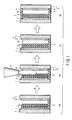
- the photosensitized solar cell of the present invention comprises a substrate having a light-receiving surface, a transparent conductive film formed on the inner surface of the substrate, an n-type semiconductor electrode formed on the transparent conductive film and having a dye adsorbed on the surface, a counter electrode having a counter substrate positioned to face the n-type semiconductor electrode and a conductive film formed on that surface of the counter substrate which faces the n-type semiconductor substrate, and a gel electrolyte for relaying the charge transfer between the conductive film of the counter electrode and the n-type semiconductor electrode.
- the gel electrolyte contains an electrolyte containing a reversible redox couple and a polymer of an onium salt formed between a halogen-containing compound and a compound containing at least one element A selected from the group consisting of N, P and S.
- the gel electrolyte is obtained by polymerizing the compound having said at least one element A and the halogen-containing compound contained in the electrolyte composition of the present invention by, for example, an addition reaction so as to allow the electrolyte composition to gel.
- reaction formulas (I) to (III) An example of the polymerizing reaction is shown in reaction formulas (I) to (III) given below:
- Reaction formula (I) represents the reaction to synthesize a crosslinked polymer from an onium salt having N (nitrogen) by the addition reaction between polydimethylallylamine, which is a compound having at least two atomic groups having a nitrogen atom per molecule, and 1,6-dibromobenzene, which is an organic boride having two bromine atoms per molecule.
- n in reaction formula (I) denotes a natural number of 2 or more.
- Reaction formula (II) represents the reaction to synthesize a crosslinked polymer from an onium salt having P (phosphorus) by the addition reaction between poly(phenyldimethylphosphine), which is a compound having at least two atomic groups having a phosphorus atom per molecule, and 1,6-dibromobenzene, which is an organic boride having two bromine atoms per molecule.
- n in reaction formula (II) denotes a natural number of 2 or more.
- Reaction formula (III) represents the reaction to synthesize a crosslinked polymer from an onium salt having S (sulfur) by the addition reaction between poly(diphenylsulfide), which is a compound having at least two atomic groups having a sulfur atom per molecule, and 1,6-dibromobenzene, which is an organic boride having two bromine atoms per molecule.
- n in reaction formula (III) denotes a natural number of 2 or more.
- the bond by self-organization which is a physical bond, is formed among the crosslinked polymers from the onium salt by using as the compound containing element A at least one kind of the compound represented by general formulas (2) to (8) given above, by using as the halogen-containing compound at least one kind of the compound represented by general formulas (2) to (8) given above, or by using as the compound containing element A and as the halogen-containing compound at least one kind of the compound represented by general formulas (2) to (8) given above.
- the crosslinked polymer content of the gel electrolyte can be decreased so as to improve the electrical conductivity of the gel electrolyte.
- the transparent conductive film prefferably be low in visible range absorption and to have an electrical conductivity. It is desirable for the transparent conductive film to be formed of a tin oxide film doped with fluorine or indium or a zinc oxide film doped with fluorine or indium. Also, in order to prevent the increase in resistivity by improving the conductivity, it is desirable to use a metal matrix having a low resistivity such as a wire in combination with the transparent conductive film.
- the n-type semiconductor electrode is desirable for the n-type semiconductor electrode to be formed of a transparent semiconductor that is low in visible range absorption.
- a metal oxide semiconductor is desirable as such a semiconductor.
- transition metals such as titanium, zirconium, hafnium, strontium, zinc, indium, yttrium, lanthanum, vanadium, niobium, tantalum,
- the dyes absorbed on the surface of the n-type semiconductor electrode include, for example, a transition metal complex of ruthenium-tris type, a transition metal complex of ruthenium-bis type, a transition metal complex of osmium-tris type, a transition metal complex of osmium-bis type, ruthenium-cis-diaqua-bipyridyl complexes, phthalocyanine and porphyrin.
- the counter substrate prefferably be low in visible range absorption and to have conductivity. It is also desirable for the counter substrate to be formed of a tin oxide film or a zinc oxide film.
- the conductive film can be formed of a metal such as platinum, gold or silver.
- the solar cell of the present invention can be formed, for example, as follows.
- a cell unit comprising a substrate having a light-receiving surface, a transparent conductive film formed on the inner surface of the substrate, an n-type semiconductor electrode formed on the transparent conductive film and having a dye adsorbed on the surface, and a counter electrode having a counter substrate facing the n-type semiconductor electrode and a conductive film formed on that surface of the counter substrate which faces the n-type semiconductor electrode.
- the electrolyte composition of the present invention which is a gel electrolyte precursor composition
- the gel electrolyte precursor composition is allowed to gel so as to obtain the photosensitized solar cell of the present invention.
- the heating temperature it is desirable to heat the cell unit in the gelling step. It is desirable for the heating temperature to fall within a range of between 50°C and 200°C. If the heating temperature is lower than 50°C, the polymerization degree of the crosslinked polymer from the onium salt is lowered so as to make it difficult to achieve a desired gelling. On the other hand, if the heating temperature exceeds 200°C, the dye tends to be decomposed. More preferably, the heating temperature should fall within a range of between 70°C and 150°C.
- the electrolyte composition of the present invention described above contains an electrolyte containing at least one kind of an imidazolium salt selected from the group consisting of 1-methyl-3-propyl imidazolium iodide, 1-methyl-3-isopropyl imidazolium iodide, 1-methyl-3-butyl imidazolium iodide, 1-methyl-3-isobutyl imidazolium iodide and 1-methyl-3-sec-butyl imidazolium iodide; a halogen-containing compound dissolved in the electrolyte; and a compound dissolved in the electrolyte and containing at least one element A selected from the group consisting of N, P and S, the compound being capable of forming an onium salt together with the halogen-containing compound.
- the particular electrolyte composition forms a polymer in the presence of iodine (I 2 ) so as to gel.
- the polymer acting as a gelling agent can be synthesized by the addition reaction between the compound containing said at least one element A and the halogen-containing compound, making it possible to form a polymer in the presence of iodine or an ionic medium so as to convert the electrolyte composition into a gelled composition. It follows that by-products are not formed in the gelling step. In addition, since the electrolyte composition is caused to gel by a small amount (several %) of the polymer, it is possible to improve the conductivity of the gel electrolyte.
- the electrolyte composition of the present invention which contains a novel electrolyte, permits suppressing the change in the composition of the gel electrolyte.
- the electrolyte composition of the present invention is injected into the gap between the n-type semiconductor electrode and the conductive film and is allowed to permeate the n-type semiconductor electrode. Then, the electrolyte composition is allowed to gel so as to obtain a photosensitized solar cell comprising the gel electrolyte.
- the particular photosensitized solar cell thus obtained produces prominent effects as described in items (1) to (8) given below:
- the electrolyte composition used in the solar cell of the present invention at least one kind of the composition selected from the compositions represented by general formulas (2) to (8) is used as the compound having element A, at least one kind of the composition selected from the compositions represented by general formulas (2) to (8) is used as the halogen-containing compound, or at least one kind of the composition selected from the compositions represented by general formulas (2) to (8) is used as the compound having element A and as the halogen-containing compound.
- the electrolyte composition it is possible to allow the electrolyte composition to gel by the addition reaction between the compound having element A and the halogen-containing compound and by the physical mutual function among the polymer molecules which is formed by the addition reaction, making it possible to decrease the amount of the polymer in the electrolyte.
- the compound having element A and the halogen-containing compound are polymerized via chemical bonds, it is possible to avoid occurrence of the phase transfer in the gel electrolyte when the temperature of the solar cell is elevated. As a result, it is possible to obtain a solar cell in which the liquid leakage is prevented when the temperature is elevated and which is capable of maintaining a high energy conversion efficiency when the temperature is elevated.
- the electrolyte composition according to another embodiment of the present invention comprises:
- the gelling agent contained in the gel electrolyte i.e., a polymer of an onium salt formed by the reaction between a compound having the nitrogen-containing atomic group referred to above and a halogen-containing compound, serves to suppress the absorption of the solar light so as to increase the transparency of the gel electrolyte.
- a polymer of an onium salt formed by the reaction between a compound having the nitrogen-containing atomic group referred to above and a halogen-containing compound serves to suppress the absorption of the solar light so as to increase the transparency of the gel electrolyte.
- the ratio of the solar light contributing to the photoelectric conversion to the entire solar light irradiating the solar cell and to suppress the deterioration of the polymer of the onium salt caused by the solar light irradiation.
- a paste was produced by adding nitric acid to a high purity titanium oxide (anatase) powder having an average primary particle diameter of 30 nm, kneading those together with pure water, and stabilizing a resulting material by a surfactant.
- the paste was printed on a dense portion formed on a glass substrate by screen printing and then heat-treated at 450°C, whereby a 2- ⁇ m thick n-type semiconductor electrode layer made of a titanium oxide (anatase) was formed.
- an 8- ⁇ m thick n-type semiconductor electrode 4 made of anatase-phase titanium oxide 3 was formed finally on a fluoride-doped tin oxide conductive film 2 as a transparent conductive film.
- the n-type semiconductor electrode 4 had a roughness factor of 1,500. The roughness factor was determined from a nitrogen absorption amount for a projection area of the substrate.
- the substrate was immersed for 4 hours in a dried ethanol solution (temperature: about 80°C) of 3 ⁇ 10 -4 mol of [cis-bis(anato)-N,N-bis(2,2'-dipyridyl-4,4'-dicarboxylic)-ruthenium (II) hydrate] and then lifted in an argon flow, whereby a ruthenium complex as a dye was carried by the surface of the n-type semiconductor electrode 4.
- a glass substrate 7 on which platinum-added, fluorine-doped tin oxide electrode 6 as a counter electrode 5 was placed on the above substrate 1 formed with the n-type semiconductor electrode 4 by using spacers having a diameter of 15 ⁇ m, and the two substrates were fixed to each other by applying an epoxy resin 8 to a peripheral portion except an electrolyte liquid inlet.
- FIG. 1(a) is a cross sectional view showing the photovoltaic device unit thus obtained.
- An electrolyte was prepared by dissolving 0.5M of tetrapropylammonium iodide, 0.02M of potassium iodide, and 0.09M of iodine in 1-methyl-3-propyl imidazolium iodide. Then, 0.3g of poly(4-vinylpyridine), which is a compound having a nitrogen (N) element, was dissolved in 10g of the electrolyte, followed by further dissolving 0.3g of 1,6-dibromohexane, which is an organic bromide, in the resultant electrolyte so as to obtain an electrolyte composition 10, which is a precursor of a gel electrolyte.
- poly(4-vinylpyridine) which is a compound having a nitrogen (N) element
- the electrolyte composition 10 was poured into an open portion of the photovoltaic device unit through a pouring port 9 so as to permit the electrolyte composition 10 to permeate into the n-type semiconductor electrode 4 and to be poured into the gap between the n-type semiconductor electrode 4 and a tin oxide electrode 6 (conductive film 6).
- FIG. 1(d) is a cross sectional view showing the solar cell thus obtained.
- a transparent conductive film 2 is formed on a glass substrate 1, and a transparent n-type semiconductor electrode 4 is formed on the transparent conductive film 2.
- the semiconductor electrode 4, which is an aggregate of fine particles 3, has a very large surface area. Also, a monomolecular layer of dye is formed on the surface of the transparent semiconductor electrode 4. It is possible for the surface of the transparent semiconductor electrode 4 to have a fractal shape having a self-similarity like a resin-like structure.
- a counter electrode 5 consists of a glass substrate 7 and a conductive film 6 formed on that surface of the glass substrate 7 which faces the semiconductor electrode 4.
- a gel electrolyte 10 is held in the pores of the semiconductor electrode 4 and is interposed between the semiconductor electrode 4 and the conductive film 6.
- An electrolyte was prepared by dissolving 0.03M of iodine in 1-methyl-3-propyl imidazolium iodide. Then, 0.3g of poly(4-vinylpyridine), which is a compound having a nitrogen (N) element, was dissolved in 10g of the electrolyte, followed by further dissolving 0.3g of 1,6-dibromohexane, which is an organic bromide, in the resultant electrolyte so as to obtain an electrolyte composition, which is a precursor of a gel electrolyte.
- poly(4-vinylpyridine) which is a compound having a nitrogen (N) element
- a dye sensitized solar cell was prepared as in Example 1 except the use of the electrolyte composition prepared as described above.
- An electrolyte was prepared by dissolving 0.03M of iodine in 1-methyl-3-propyl imidazolium iodide. Then, 0.3g of 4,4-bipyridyl, which is a compound having a nitrogen (N) element, was dissolved in 10g of the electrolyte, followed by further dissolving 0.3g of 1,2,4,5-tetrakis(bromomethyl)benzene, which is an organic bromide, in the resultant electrolyte so as to obtain an electrolyte composition, which is a precursor of a gel electrolyte.
- a dye sensitized solar cell was prepared as in Example 1 except the use of the electrolyte composition prepared as described above.
- a gel electrolyte composition was synthesized. Specifically, 310.3g (2 mol) of 2-isocyanateethylmethacrylate was mixed with 114g (1 mol) of diaminocyclohexane, and the mixture was dissolved in 1 L (liter) of dichloromethane. Then, 3g of a polymerization inhibitor and a catalyst were added to the solution while stirring the solution, followed by condensing the system under a reduced pressure by using an evaporator so as to obtain 300g of 1,2-bis (methacrylooxyethylureide)cyclohexane having a molecular weight of 422.
- 0.1g of the nitrogen-containing organic compound represented by formula (9), 10g of 1-methyl-3-propylimidazoliumiodide (electrically conductive material), 0.1g of iodine and 0.1g of 1,2,4,5-tetrakis(bromomethyl) benzene (halogen-containing compound) were mixed so as to prepare a solution.
- the solution was found to gel so as to obtain a gel electrolyte composition.
- the gel electrolyte composition was heated at 60°C for 10 minutes. It has been found that the gelled state is not collapsed even if the gel electrolyte composition is heated to 80°C.
- a dye sensitized solar cell was manufactured as in Example 1 except the use of the electrolyte composition thus prepared.
- a dye sensitized solar cell was manufactured as in Example 1 except the use of the electrolyte composition thus prepared.
- a dye sensitized solar cell was manufactured as in Example 1 except the use of the electrolyte composition thus prepared.
- a dye sensitized solar cell was manufactured as in Example 1 except the use of the electrolyte composition thus prepared.
- a dye sensitized solar cell was manufactured as in Example 1 except the use of the electrolyte composition thus prepared.
- a dye sensitized solar cell was manufactured as in Example 1 except the use of the electrolyte composition thus prepared.
- a dye sensitized solar cell was manufactured as in Example 1 except the use of the electrolyte composition thus prepared.
- a dye sensitized solar cell was manufactured as in Example 1 except the use of the electrolyte composition thus prepared.
- 0.3g of bipyridyl was dissolved in 10g of the electrolyte similar to that used in Example 1. Then, 0.3g of the halogen-containing compound represented by general formula (3) given previously, in which R 1 represents bromine, R 1' represents bromine, R 5 represents oxide, R 6 represents sec-butyl group, R 7 represents sec-butyl group, R 8 represents dodecylene, and R 9 represents oxide, was dissolved in the resultant solution so as to obtain an electrolyte composition, which is a precursor of the gel electrolyte.
- a dye sensitized solar cell was manufactured as in Example 1 except the use of the electrolyte composition thus prepared.
- 0.3g of terpyridyl was dissolved in 10g of the electrolyte similar to that used in Example 1. Then, 0.3g of the halogen-containing compound represented by general formula (4) given previously, in which R 1 represents iodine, R 10 represents octyl group, and R 11 represents carbonyl, was dissolved in the resultant solution so as to obtain an electrolyte composition, which is a precursor of the gel electrolyte.
- a dye sensitized solar cell was manufactured as in Example 1 except the use of the electrolyte composition thus prepared.
- a dye sensitized solar cell was manufactured as in Example 1 except the use of the electrolyte composition thus prepared.
- 0.3g of bipyridyl was dissolved in 10g of the electrolyte similar to that used in Example 1. Then, 0.3g of the halogen-containing compound represented by general formula (6) given previously, in which R 1 represents bromine, R 1' represents bromine, R 14 represents carbonyl, R 15 represents carbonyl, R 16 decylene represents, and R 17 represents decylene, was dissolved in the resultant solution so as to obtain an electrolyte composition, which is a precursor of the gel electrolyte.
- a dye sensitized solar cell was manufactured as in Example 1 except the use of the electrolyte composition thus prepared.
- 0.3g of terpyridyl was dissolved in 10g of the electrolyte similar to that used in Example 1. Then, 0.3g of the halogen-containing compound represented by general formula (7) given previously, in which R 1 represents bromine, R 1' represents bromine, R 18 represents decylene, and R 19 represents decylene, was dissolved in the resultant solution so as to obtain an electrolyte composition, which is a precursor of the gel electrolyte.
- a dye sensitized solar cell was manufactured as in Example 1 except the use of the electrolyte composition thus prepared.
- a dye sensitized solar cell was manufactured as in Example 1 except the use of the electrolyte composition thus prepared.
- a dye sensitized solar cell was manufactured as in Example 1, except that the electrolyte composition thus prepared was used and that the heat treating temperature for the gelling was set at 100°C.
- a dye sensitized solar cell was manufactured as in Example 1, except that the electrolyte composition thus prepared was used and that the heat treating temperature for the gelling was set at 100°C.
- a dye sensitized solar cell was manufactured as in Example 1, except that the electrolyte composition thus prepared was used and that the heat treating temperature for the gelling was set at 100°C.
- a dye sensitized solar cell was manufactured as in Example 1, except that the electrolyte composition thus prepared was used and that the heat treating temperature for the gelling was set at 100°C.
- a dye sensitized solar cell was manufactured as in Example 1, except that the electrolyte composition thus prepared was used and that the heat treating temperature for the gelling was set at 100°C.
- a dye sensitized solar cell was manufactured as in Example 1, except that the electrolyte composition thus prepared was used and that the heat treating temperature for the gelling was set at 100°C.
- a dye sensitized solar cell was manufactured as in Example 1, except that the electrolyte composition thus prepared was used and that the heat treating temperature for the gelling was set at 100°C.
- a dye sensitized solar cell was manufactured as in Example 1, except that the electrolyte composition thus prepared was used and that the heat treating temperature for the gelling was set at 100°C.
- a dye sensitized solar cell was manufactured as in Example 1, except that the electrolyte composition thus prepared was used and that the heat treating temperature for the gelling was set at 100°C.
- a dye sensitized solar cell was manufactured as in Example 1, except that the electrolyte composition thus prepared was used and that the heat treating temperature for the gelling was set at 100°C.
- a dye sensitized solar cell was manufactured as in Example 1, except that the electrolyte composition thus prepared was used and that the heat treating temperature for the gelling was set at 100°C.
- a dye sensitized solar cell was manufactured as in Example 1, except that the electrolyte composition thus prepared was used and that the heat treating temperature for the gelling was set at 100°C.
- a solution was prepared by dissolving 0.09M of iodine in a mixed solvent consisting of 99.5% by weight of 1-methyl-3-propyl imidazolium iodide and 0.5% by weight of water. Then, 0.2g of poly(4-vinylpyridine), which is a nitrogen-containing compound, was dissolved in 10g of the solution thus prepared. Further, 0.2g of 1,6-dibromohexane, which is an organic bromide, was dissolved in the resultant solution so as to obtain an electrolyte composition, which is a precursor of a gel electrolyte.
- a dye sensitized solar cell was manufactured as in Example 1, except that used was the electrolyte composition thus prepared.
- a solution was prepared by dissolving 0.5M of tetrapropylammonium iodide, and 0.09M of iodine in a solvent prepared by adding propylene carbonate to 1-methyl-3-propyl imidazolium iodide. Then, 0.3g of poly(4-vinylpyridine) was dissolved in 10g of the solution thus prepared. Further, 0.3g of 1,6-dibromohexane, which is an organic bromide, was dissolved in the resultant solution so as to obtain an electrolyte composition, which is a precursor of a gel electrolyte. The content of propylene carbonate in the electrolyte composition was found to be 20% by weight.
- a dye sensitized solar cell was manufactured as in Example 1, except that used was the electrolyte composition thus prepared.
- An electrolyte was prepared by dissolving 0.5M of potassium iodide, and 0.09M of iodine in 1-methyl-3-isopropyl imidazolium iodide. Then, 0.3g of poly(4-vinylpyridine) was dissolved in 10g of the electrolyte thus prepared. Further, 0.3g of 1,6-dibromohexane, which is an organic bromide, was dissolved in the resultant solution so as to obtain an electrolyte composition, which is a precursor of a gel electrolyte.
- a dye sensitized solar cell was manufactured as in Example 1, except that used was the electrolyte composition thus prepared.
- An electrolyte was prepared by dissolving 0.09M of iodine in a mixed solvent consisting of 1-methyl-3-propyl imidazolium iodide and 1-methyl-3-butyl imidazolium iodide. Then, 0.3g of poly(4-vinylpyridine) was dissolved in 10g of the electrolyte thus prepared. Further, 0.3g of 1,6-dibromohexane, which is an organic bromide, was dissolved in the resultant solution so as to obtain an electrolyte composition, which is a precursor of a gel electrolyte.
- a dye sensitized solar cell was manufactured as in Example 1, except that used was the electrolyte composition thus prepared.
- the electrolyte composition thus prepared was poured through a pouring port into the open portion of a photovoltaic device unit similar to that described previously in conjunction with Example 1 so as to allow the electrolyte composition to permeate into the n-type semiconductor electrode and to be poured into the gap between the n-type semiconductor electrode and the tin oxide electrode (conductive film).
- the open portion of the photovoltaic device unit was sealed with an epoxy resin, followed by heating on a hot plate at 50°C for 200 minutes so as to manufacture a photovoltaic device, i.e., a dye sensitized solar cell.
- An electrolyte was prepared by dissolving 0.5M of lithium iodide and 0.05M of iodine in acetonitrile. Added to 90% by weight (90g) of the electrolyte was 10% by weight (10g) of poly(4-vinylpyridine) having a molecular weight of 10,000. However, since poly(4-vinylpyridine) was not dissolved in acetonitrile, it was impossible to obtain an electrolyte composition.
- An electrolyte was prepared by dissolving 0.5M of lithium iodide and 0.05M of iodine in propylene carbonate. Then, 10% by weight (10g) of poly(4-vinylpyridine) having a molecular weight of 2,000 was dissolved in 90% by weight of the electrolyte thus prepared. Further, an electrolyte composition, which was a precursor of a gel electrolyte, was obtained by dissolving 10g of 1,6-dibromohexane in the resultant solution.
- a dye sensitized solar cell was manufactured as in Example 1, except that used was the electrolyte composition thus prepared.
- the solar cell obtained in each of Examples 1 to 34 and the Comparative Examples 1 and 3 was dismantled so as to observe the state of the electrolyte.
- the electrolyte was found to have gelled.
- the photovoltaic efficiency in the case of irradiating the solar cell with a quasi-solar light having an intensity of 100 mW/cm 2 was measured in respect of the solar cell obtained in each of Examples 1 to 34 and the Comparative Examples 1 and 3.
- Table 1 shows the result.
- the photovoltaic efficiency was measured in the case of storing the solar cell at 100°C for 1 month, followed by irradiating the solar with a quasi-solar light having an intensity of 100 mW/cm 2 in respect of the solar cell obtained in each of Examples 1 to 34 and the Comparative Examples 1 and 3.
- the photovoltaic efficiency thus obtained was compared with the photovoltaic efficiency before the storage so as to obtain the decrease in the photovoltaic efficiency caused by the storage of the solar cell at 100°C for 1 month.
- Table 1 shows the result.
- the rate of decrease smaller than 10% is marked A in Table 1.
- the rate of decrease falling within a range of between 10% and 50% is marked B.
- the rate of decrease larger than 50% is marked C in Table 1.
- the solar cell in each of Examples 1 to 34 exhibits a high energy conversion efficiency and is low in the rate of decrease of the energy conversion efficiency caused by the temperature elevation, compared with the solar cell of the Comparative Examples 1 and 3.
- the solar light was incident on the n-type semiconductor electrode.
- the technical idea of the present invention can also be applied to a solar cell constructed such that the solar light is incident on the counter electrode.
- the present invention provides an electrolyte composition that permits overcoming the problems inherent in the wet photosensitized solar cell and the full-solid-state photosensitized solar cell so as to improve the energy conversion efficiency of the solar cell and also permits obtaining a high energy conversion efficiency when the solar cell is used under a high temperature environment, and also provides a photosensitized solar cell using the particular electrolyte composition and a method of manufacturing the photosensitized solar cell.
Applications Claiming Priority (2)
| Application Number | Priority Date | Filing Date | Title |
|---|---|---|---|
| JP26976299 | 1999-09-24 | ||
| JP26976299 | 1999-09-24 |
Publications (3)
| Publication Number | Publication Date |
|---|---|
| EP1087412A2 true EP1087412A2 (fr) | 2001-03-28 |
| EP1087412A3 EP1087412A3 (fr) | 2003-12-10 |
| EP1087412B1 EP1087412B1 (fr) | 2008-10-01 |
Family
ID=17476805
Family Applications (1)
| Application Number | Title | Priority Date | Filing Date |
|---|---|---|---|
| EP00308307A Expired - Lifetime EP1087412B1 (fr) | 1999-09-24 | 2000-09-22 | Composition d'électrolyte, cellule solaire employant cette composition d'électrolyte, et méthode de fabrication de cette cellule solaire |
Country Status (6)
| Country | Link |
|---|---|
| US (1) | US6384321B1 (fr) |
| EP (1) | EP1087412B1 (fr) |
| KR (1) | KR100537126B1 (fr) |
| AT (1) | ATE409947T1 (fr) |
| AU (1) | AU739381B2 (fr) |
| DE (1) | DE60040372D1 (fr) |
Cited By (15)
| Publication number | Priority date | Publication date | Assignee | Title |
|---|---|---|---|---|
| EP1180774A2 (fr) * | 2000-08-15 | 2002-02-20 | Fuji Photo Film Co., Ltd. | Dispositif de conversion photoélectrique et son procédé de fabrication |
| WO2002078115A1 (fr) | 2001-03-26 | 2002-10-03 | Sharp Corporation | Pile solaire sensibilisee par un colorant |
| WO2004017452A1 (fr) * | 2002-08-13 | 2004-02-26 | Bridgestone Corporation | Perfectionnement apporté à une cellule solaire à colorant |
| US6858158B2 (en) | 2002-01-25 | 2005-02-22 | Konarka Technologies, Inc. | Low temperature interconnection of nanoparticles |
| US6900382B2 (en) | 2002-01-25 | 2005-05-31 | Konarka Technologies, Inc. | Gel electrolytes for dye sensitized solar cells |
| US6913713B2 (en) | 2002-01-25 | 2005-07-05 | Konarka Technologies, Inc. | Photovoltaic fibers |
| EP1551075A1 (fr) * | 2002-09-25 | 2005-07-06 | Sharp Corporation | Photopile sensibilisee aux couleurs |
| US6924427B2 (en) | 2002-01-25 | 2005-08-02 | Konarka Technologies, Inc. | Wire interconnects for fabricating interconnected photovoltaic cells |
| EP1873862A1 (fr) * | 2005-04-11 | 2008-01-02 | Nippon Kayaku Kabushiki Kaisha | Composition d électrolyte pour convertisseur photoélectrique et convertisseur photoélectrique l'utilisant |
| EP1880418A2 (fr) * | 2005-05-09 | 2008-01-23 | Solaris Nanosciences, Inc. | Cellule solaire rechargeable sensibilisee par application d'un colorant |
| EP2085985A2 (fr) | 2003-04-30 | 2009-08-05 | Ecole Polytechnique Fédérale de Lausanne (EPFL) | Cellule solaire sensibilisée aux colorants |
| US7932464B2 (en) | 2002-01-25 | 2011-04-26 | Konarka Technologies, Inc. | Methods of scoring for fabricating interconnected photovoltaic cells |
| US7932404B2 (en) | 2004-07-29 | 2011-04-26 | Ecole Polytechnique Federale De Lausanne (Epfl) | 2,2-bipyridine ligand, sensitizing dye and dye sensitized solar cell |
| US8071874B2 (en) | 2002-01-25 | 2011-12-06 | Konarka Technologies, Inc. | Photovoltaic cells incorporating rigid substrates |
| EP2509085A3 (fr) * | 2011-04-06 | 2014-07-09 | Samsung SDI Co., Ltd. | Électrolyte pour cellule solaire sensibilisée aux colorants et cellule solaire sensibilisée aux colorants l'incluant |
Families Citing this family (54)
| Publication number | Priority date | Publication date | Assignee | Title |
|---|---|---|---|---|
| DE60029151T2 (de) * | 1999-03-01 | 2007-05-31 | Fuji Photo Film Co., Ltd., Minami-Ashigara | Photoelektrochemische Zelle mit einem Elektrolyten aus Flüssigkristallverbindungen |
| US6384321B1 (en) * | 1999-09-24 | 2002-05-07 | Kabushiki Kaisha Toshiba | Electrolyte composition, photosensitized solar cell using said electrolyte composition, and method of manufacturing photosensitized solar cell |
| EP1178542A4 (fr) * | 1999-12-27 | 2006-03-08 | Seiko Epson Corp | Cellule photovoltaique et unite correspondante |
| US20050284513A1 (en) * | 2002-08-08 | 2005-12-29 | Christoph Brabec | Chip card comprising an integrated energy converter |
| US7414188B2 (en) * | 2002-01-25 | 2008-08-19 | Konarka Technologies, Inc. | Co-sensitizers for dye sensitized solar cells |
| US7205473B2 (en) * | 2002-01-25 | 2007-04-17 | Konarka Technologies, Inc. | Photovoltaic powered multimedia greeting cards and smart cards |
| US20030192584A1 (en) * | 2002-01-25 | 2003-10-16 | Konarka Technologies, Inc. | Flexible photovoltaic cells and modules formed using foils |
| US6949400B2 (en) * | 2002-01-25 | 2005-09-27 | Konarka Technologies, Inc. | Ultrasonic slitting of photovoltaic cells and modules |
| US6706963B2 (en) * | 2002-01-25 | 2004-03-16 | Konarka Technologies, Inc. | Photovoltaic cell interconnection |
| US6919119B2 (en) * | 2000-05-30 | 2005-07-19 | The Penn State Research Foundation | Electronic and opto-electronic devices fabricated from nanostructured high surface to volume ratio thin films |
| JP2001345119A (ja) * | 2000-05-31 | 2001-12-14 | Matsushita Electric Ind Co Ltd | 非水電解質電池および非水電解液 |
| US6552405B2 (en) * | 2000-07-27 | 2003-04-22 | Kyocera Corporation | Photoelectric conversion device and manufacturing method thereof |
| JP4222466B2 (ja) * | 2001-06-14 | 2009-02-12 | 富士フイルム株式会社 | 電荷輸送材料、それを用いた光電変換素子及び光電池、並びにピリジン化合物 |
| US7126054B2 (en) * | 2001-06-28 | 2006-10-24 | Kabushiki Kaisha Toshiba | Raw material kit for electrolytic composition, electrolytic composition, and dye-sensitized solar cell |
| JP2003179243A (ja) * | 2001-08-31 | 2003-06-27 | Basf Ag | 光電池活性材料およびこれを含む電池 |
| DE60132450T2 (de) * | 2001-09-04 | 2008-04-17 | Sony Deutschland Gmbh | Solarzelle und Herstellungsmethode |
| JP3735570B2 (ja) * | 2001-12-28 | 2006-01-18 | 株式会社東芝 | 電解質組成物用原料キット、光増感型太陽電池のゲル電解質用電解質組成物、光増感型太陽電池及び光増感型太陽電池の製造方法 |
| US7202412B2 (en) * | 2002-01-18 | 2007-04-10 | Sharp Kabushiki Kaisha | Photovoltaic cell including porous semiconductor layer, method of manufacturing the same and solar cell |
| WO2003065393A2 (fr) * | 2002-01-25 | 2003-08-07 | Konarka Technologies, Inc. | Afficheurs a photopiles integrees |
| KR100560208B1 (ko) * | 2002-03-12 | 2006-03-10 | 에스케이씨 주식회사 | 상온에서 겔화가능한 겔 고분자 전해질용 조성물 |
| US20040120974A1 (en) * | 2002-12-23 | 2004-06-24 | Ajinomoto Usa, Inc. | Powder concentrates, methods of preparing the same, methods of using the same, and emulsified personal care products prepared from the same |
| IL153895A (en) * | 2003-01-12 | 2013-01-31 | Orion Solar Systems Ltd | Solar cell device |
| US8586861B2 (en) * | 2003-01-12 | 2013-11-19 | 3Gsolar Photovoltaics Ltd. | Solar cell device |
| JP2004327167A (ja) * | 2003-04-23 | 2004-11-18 | Sony Corp | 電解液の注入方法、湿式光電変換素子の製造方法および湿式装置の製造方法 |
| KR100499051B1 (ko) * | 2003-06-25 | 2005-07-04 | 한국전자통신연구원 | 이미다졸리움계 액체형 전해질을 포함하는 염료 감응 태양전지 |
| CN1307728C (zh) * | 2003-07-25 | 2007-03-28 | 鸿富锦精密工业(深圳)有限公司 | 太阳能电池及其电极 |
| JP4459578B2 (ja) * | 2003-09-08 | 2010-04-28 | 株式会社フジクラ | 色素増感太陽電池 |
| JP4197637B2 (ja) * | 2003-09-29 | 2008-12-17 | 株式会社東芝 | 光増感型太陽電池及びその製造方法 |
| US7411716B2 (en) * | 2004-04-19 | 2008-08-12 | Lg Chem, Ltd. | Gel polymer electrolyte containing ionic liquid and electrochromic device using the same |
| KR101058101B1 (ko) * | 2004-06-26 | 2011-08-24 | 삼성에스디아이 주식회사 | 전해액 조성물 및 이를 이용한 태양전지 |
| WO2006018938A1 (fr) * | 2004-08-17 | 2006-02-23 | National University Corporation Kyushu Institute Of Technology | Précurseur de couche d’électrolyte en gel pour cellule solaire sensibilisée par colorant et cellule solaire sensibilisée par colorant |
| KR100553337B1 (ko) * | 2004-08-18 | 2006-02-21 | 한국과학기술연구원 | 이미다졸륨기를 함유한 공중합체, 이의 제조 방법, 이를함유하는 태양전지용 전해질 조성물 및 이를 전해질로서포함하는 염료감응 태양 전지 |
| JP5008841B2 (ja) * | 2005-08-02 | 2012-08-22 | 株式会社フジクラ | 電極基板の製造方法、光電変換素子および色素増感太陽電池 |
| JP2009506360A (ja) * | 2005-08-22 | 2009-02-12 | コナルカ テクノロジーズ インコーポレイテッド | 組込型の光電池を備えるディスプレイ |
| US20070079867A1 (en) * | 2005-10-12 | 2007-04-12 | Kethinni Chittibabu | Photovoltaic fibers |
| TWI306314B (en) * | 2006-09-27 | 2009-02-11 | Ind Tech Res Inst | Method of sealing solar cells |
| US9184317B2 (en) | 2007-04-02 | 2015-11-10 | Merck Patent Gmbh | Electrode containing a polymer and an additive |
| US20110203644A1 (en) * | 2010-02-22 | 2011-08-25 | Brite Hellas Ae | Quasi-solid-state photoelectrochemical solar cell formed using inkjet printing and nanocomposite organic-inorganic material |
| KR20110105449A (ko) * | 2010-03-19 | 2011-09-27 | 도레이첨단소재 주식회사 | 염료감응태양전지용 고분자전해질 및 이를 이용한 염료감응태양전지의 제조방법 |
| KR101348391B1 (ko) * | 2011-07-21 | 2014-01-14 | 한국에너지기술연구원 | 이미다졸륨염이 화학적으로 결합된 나노입자, 이의 제조방법 및 이를 포함하는 염료감응 태양전지용 나노젤형 전해질 |
| KR101323723B1 (ko) * | 2012-02-28 | 2013-10-30 | 한국과학기술원 | 겔-형 전해질을 포함하는 염료감응 태양전지의 제조 방법 |
| KR101381873B1 (ko) * | 2012-04-13 | 2014-04-14 | 한국과학기술연구원 | 고분자 젤 전해질 조성물, 이의 제조방법 및 이를 포함하는 염료감응 태양전지 |
| ES2568623T3 (es) | 2012-05-18 | 2016-05-03 | Isis Innovation Limited | Dispositivo optoeléctrico que comprende material de armazón poroso y perovskitas |
| EP2850669B1 (fr) * | 2012-05-18 | 2016-02-24 | Isis Innovation Limited | Dispositif photovoltaïque comprenant des pérovskites |
| GB201208793D0 (en) | 2012-05-18 | 2012-07-04 | Isis Innovation | Optoelectronic device |
| ES2438441B1 (es) * | 2012-06-14 | 2014-10-22 | Onyx Solar Energy, S.L. | Suelo transitable fotovoltáico. |
| KR102296283B1 (ko) | 2012-09-18 | 2021-08-31 | 옥스포드 유니버시티 이노베이션 리미티드 | 광전자 디바이스 |
| WO2014109610A1 (fr) * | 2013-01-10 | 2014-07-17 | 한국화학연구원 | Procédé de fabrication d'une cellule solaire hybride organique-inorganique à haut rendement |
| KR101406969B1 (ko) * | 2013-05-10 | 2014-06-20 | 한국과학기술연구원 | 고체 전해질 염료감응형 태양전지의 제조 방법 및 이에 이용되는 전해질 충진 장치 |
| KR101492022B1 (ko) * | 2014-03-11 | 2015-02-11 | 한국화학연구원 | 무/유기 하이브리드 페로브스카이트 화합물계 태양전지 |
| WO2015187227A2 (fr) * | 2014-03-13 | 2015-12-10 | Duke University | Plate-forme électronique pour la détection et la commande de réactions électrochimiques |
| JP6297891B2 (ja) * | 2014-04-01 | 2018-03-20 | 株式会社リコー | 有機材料及び光電変換素子 |
| ES2597952B1 (es) * | 2015-07-22 | 2017-12-01 | Universidad De Almería | Células solares constituida por agua y complejos de rutenio con fosfinas acuosolubles: un nuevo tipo de células solares |
| US10692653B2 (en) * | 2017-10-27 | 2020-06-23 | Yageo Corporation | Ceramic sintered body and passive component including the same |
Citations (3)
| Publication number | Priority date | Publication date | Assignee | Title |
|---|---|---|---|---|
| EP0718288A1 (fr) * | 1994-12-21 | 1996-06-26 | Asulab S.A. | Sels liquides hydrophobes, leur préparation et leur application en électrochimie |
| EP0911841A2 (fr) * | 1997-10-23 | 1999-04-28 | Fuji Photo Film Co., Ltd. | Dispositif de conversion photo-électrique et cellule photoélectrochimique |
| EP0924724A2 (fr) * | 1997-12-16 | 1999-06-23 | Fuji Photo Film Co., Ltd. | Dispositif de conversion photoélectrique et cellule photo-électrochimique |
Family Cites Families (10)
| Publication number | Priority date | Publication date | Assignee | Title |
|---|---|---|---|---|
| JP3599859B2 (ja) | 1994-12-29 | 2004-12-08 | 石原産業株式会社 | 多孔性物質−高分子固体電解質複合体およびその製造方法ならびにそれを用いた光電変換素子 |
| JPH09259943A (ja) * | 1996-03-19 | 1997-10-03 | Tokyo Gas Co Ltd | 湿式太陽電池 |
| GB9619133D0 (en) * | 1996-09-13 | 1996-10-23 | Secr Defence | An electrolyte |
| WO1998029358A2 (fr) * | 1996-12-30 | 1998-07-09 | Hydro-Quebec | Materiaux carbones modifies en surface |
| JPH11250944A (ja) * | 1998-02-26 | 1999-09-17 | Nikon Corp | 湿式太陽電池 |
| JP4076620B2 (ja) * | 1998-03-30 | 2008-04-16 | 住友大阪セメント株式会社 | 色素増感型太陽電池 |
| US6183914B1 (en) * | 1998-09-17 | 2001-02-06 | Reveo, Inc. | Polymer-based hydroxide conducting membranes |
| US6384321B1 (en) * | 1999-09-24 | 2002-05-07 | Kabushiki Kaisha Toshiba | Electrolyte composition, photosensitized solar cell using said electrolyte composition, and method of manufacturing photosensitized solar cell |
| JP4008669B2 (ja) * | 2001-03-22 | 2007-11-14 | 株式会社東芝 | 光増感型太陽電池 |
| JP2002289268A (ja) * | 2001-03-22 | 2002-10-04 | Toshiba Corp | 光増感型太陽電池 |
-
2000
- 2000-09-22 US US09/667,562 patent/US6384321B1/en not_active Expired - Lifetime
- 2000-09-22 AU AU61246/00A patent/AU739381B2/en not_active Ceased
- 2000-09-22 DE DE60040372T patent/DE60040372D1/de not_active Expired - Lifetime
- 2000-09-22 AT AT00308307T patent/ATE409947T1/de not_active IP Right Cessation
- 2000-09-22 EP EP00308307A patent/EP1087412B1/fr not_active Expired - Lifetime
- 2000-09-23 KR KR10-2000-0055952A patent/KR100537126B1/ko not_active IP Right Cessation
Patent Citations (3)
| Publication number | Priority date | Publication date | Assignee | Title |
|---|---|---|---|---|
| EP0718288A1 (fr) * | 1994-12-21 | 1996-06-26 | Asulab S.A. | Sels liquides hydrophobes, leur préparation et leur application en électrochimie |
| EP0911841A2 (fr) * | 1997-10-23 | 1999-04-28 | Fuji Photo Film Co., Ltd. | Dispositif de conversion photo-électrique et cellule photoélectrochimique |
| EP0924724A2 (fr) * | 1997-12-16 | 1999-06-23 | Fuji Photo Film Co., Ltd. | Dispositif de conversion photoélectrique et cellule photo-électrochimique |
Non-Patent Citations (1)
| Title |
|---|
| PAPAGEORGIOU N ET AL: "The Performance and Stability of Ambient Temperature Molten Salts for Solar Cell Applications" JOURNAL OF THE ELECTROCHEMICAL SOCIETY, ELECTROCHEMICAL SOCIETY. MANCHESTER, NEW HAMPSHIRE, US, vol. 143, no. 10, October 1996 (1996-10), pages 3099-3108, XP002118482 ISSN: 0013-4651 * |
Cited By (25)
| Publication number | Priority date | Publication date | Assignee | Title |
|---|---|---|---|---|
| EP1180774A3 (fr) * | 2000-08-15 | 2004-01-28 | Fuji Photo Film Co., Ltd. | Dispositif de conversion photoélectrique et son procédé de fabrication |
| EP1180774A2 (fr) * | 2000-08-15 | 2002-02-20 | Fuji Photo Film Co., Ltd. | Dispositif de conversion photoélectrique et son procédé de fabrication |
| EP1387430A4 (fr) * | 2001-03-26 | 2009-09-09 | Sharp Kk | Pile solaire sensibilisee par un colorant |
| WO2002078115A1 (fr) | 2001-03-26 | 2002-10-03 | Sharp Corporation | Pile solaire sensibilisee par un colorant |
| EP1387430A1 (fr) * | 2001-03-26 | 2004-02-04 | Sharp Corporation | Pile solaire sensibilisee par un colorant |
| US7932464B2 (en) | 2002-01-25 | 2011-04-26 | Konarka Technologies, Inc. | Methods of scoring for fabricating interconnected photovoltaic cells |
| US7894694B2 (en) | 2002-01-25 | 2011-02-22 | Konarka Technologies, Inc. | Photovoltaic fibers |
| US6913713B2 (en) | 2002-01-25 | 2005-07-05 | Konarka Technologies, Inc. | Photovoltaic fibers |
| US6924427B2 (en) | 2002-01-25 | 2005-08-02 | Konarka Technologies, Inc. | Wire interconnects for fabricating interconnected photovoltaic cells |
| US8581096B2 (en) | 2002-01-25 | 2013-11-12 | Merck Patent Gmbh | Gel electrolytes for dye sensitized solar cells |
| US8071874B2 (en) | 2002-01-25 | 2011-12-06 | Konarka Technologies, Inc. | Photovoltaic cells incorporating rigid substrates |
| US6900382B2 (en) | 2002-01-25 | 2005-05-31 | Konarka Technologies, Inc. | Gel electrolytes for dye sensitized solar cells |
| US6858158B2 (en) | 2002-01-25 | 2005-02-22 | Konarka Technologies, Inc. | Low temperature interconnection of nanoparticles |
| WO2004017452A1 (fr) * | 2002-08-13 | 2004-02-26 | Bridgestone Corporation | Perfectionnement apporté à une cellule solaire à colorant |
| EP1551075A1 (fr) * | 2002-09-25 | 2005-07-06 | Sharp Corporation | Photopile sensibilisee aux couleurs |
| EP1551075A4 (fr) * | 2002-09-25 | 2009-04-29 | Dai Ichi Kogyo Seiyaku Co Ltd | Photopile sensibilisee aux couleurs |
| EP2085985A2 (fr) | 2003-04-30 | 2009-08-05 | Ecole Polytechnique Fédérale de Lausanne (EPFL) | Cellule solaire sensibilisée aux colorants |
| US9337435B2 (en) | 2003-04-30 | 2016-05-10 | Ecole Polytechnique Federal De Lausanne (Epfl) | Dye sensitized solar cell |
| US7932404B2 (en) | 2004-07-29 | 2011-04-26 | Ecole Polytechnique Federale De Lausanne (Epfl) | 2,2-bipyridine ligand, sensitizing dye and dye sensitized solar cell |
| US8440843B2 (en) | 2004-07-29 | 2013-05-14 | ECOLE POLYTECHNIQUE FéDéRALE DE LAUSANNE | 2, 2-bipyridine ligand, sensitizing dye and dye sensitized solar cell |
| EP1873862A4 (fr) * | 2005-04-11 | 2009-07-29 | Nippon Kayaku Kk | Composition d électrolyte pour convertisseur photoélectrique et convertisseur photoélectrique l'utilisant |
| EP1873862A1 (fr) * | 2005-04-11 | 2008-01-02 | Nippon Kayaku Kabushiki Kaisha | Composition d électrolyte pour convertisseur photoélectrique et convertisseur photoélectrique l'utilisant |
| EP1880418A4 (fr) * | 2005-05-09 | 2010-09-01 | Solaris Nanosciences Inc | Cellule solaire rechargeable sensibilisee par application d'un colorant |
| EP1880418A2 (fr) * | 2005-05-09 | 2008-01-23 | Solaris Nanosciences, Inc. | Cellule solaire rechargeable sensibilisee par application d'un colorant |
| EP2509085A3 (fr) * | 2011-04-06 | 2014-07-09 | Samsung SDI Co., Ltd. | Électrolyte pour cellule solaire sensibilisée aux colorants et cellule solaire sensibilisée aux colorants l'incluant |
Also Published As
| Publication number | Publication date |
|---|---|
| AU739381B2 (en) | 2001-10-11 |
| KR20010030478A (ko) | 2001-04-16 |
| US6384321B1 (en) | 2002-05-07 |
| AU6124600A (en) | 2001-03-29 |
| EP1087412A3 (fr) | 2003-12-10 |
| KR100537126B1 (ko) | 2005-12-16 |
| DE60040372D1 (de) | 2008-11-13 |
| ATE409947T1 (de) | 2008-10-15 |
| EP1087412B1 (fr) | 2008-10-01 |
Similar Documents
| Publication | Publication Date | Title |
|---|---|---|
| US6384321B1 (en) | Electrolyte composition, photosensitized solar cell using said electrolyte composition, and method of manufacturing photosensitized solar cell | |
| US7126054B2 (en) | Raw material kit for electrolytic composition, electrolytic composition, and dye-sensitized solar cell | |
| US6900382B2 (en) | Gel electrolytes for dye sensitized solar cells | |
| US6858158B2 (en) | Low temperature interconnection of nanoparticles | |
| JP4119267B2 (ja) | 光増感型太陽電池 | |
| US7414188B2 (en) | Co-sensitizers for dye sensitized solar cells | |
| KR100540157B1 (ko) | 복합 고분자 전해질을 포함하는 고체상 염료감응 태양전지 | |
| US20050019414A1 (en) | Low temperature interconnection of nanoparticles | |
| JP3946947B2 (ja) | 光増感型太陽電池用電解質組成物、光増感型太陽電池及び光増感型太陽電池の製造方法 | |
| JP4515948B2 (ja) | ゲル状電解質用原料キット、ゲル状電解質用電解質組成物及び光増感型太陽電池 | |
| WO2006126861A1 (fr) | Composition d'electrolyte solide contenant des materiaux cristallins liquides et piles solaires sensibilisees par un colorant et utilisant cette composition | |
| CN103429662B (zh) | 一种聚合物电解质组合物和含有所述组合物的染料敏化太阳能电池 | |
| AU2004303035B2 (en) | Electrolyte composition and photoelectric converter using same | |
| US20230104362A1 (en) | Dye sensitized photovoltaic cells | |
| JP4008669B2 (ja) | 光増感型太陽電池 | |
| Mikoshiba et al. | Anomalous increase in photocurrent density for quasi-solid dye sensitized solar cells by addition of tetra (bromomethyl) benzene | |
| JP2002289268A (ja) | 光増感型太陽電池 | |
| JP2004296373A (ja) | 光増感型太陽電池 | |
| JP2001085075A (ja) | 光電変換素子及びその製造方法 | |
| JP2005216633A (ja) | ゲル電解質、その製造方法および太陽電池 |
Legal Events
| Date | Code | Title | Description |
|---|---|---|---|
| PUAI | Public reference made under article 153(3) epc to a published international application that has entered the european phase |
Free format text: ORIGINAL CODE: 0009012 |
|
| 17P | Request for examination filed |
Effective date: 20001023 |
|
| AK | Designated contracting states |
Kind code of ref document: A2 Designated state(s): AT BE CH CY DE DK ES FI FR GB GR IE IT LI LU MC NL PT SE |
|
| AX | Request for extension of the european patent |
Free format text: AL;LT;LV;MK;RO;SI |
|
| PUAL | Search report despatched |
Free format text: ORIGINAL CODE: 0009013 |
|
| AK | Designated contracting states |
Kind code of ref document: A3 Designated state(s): AT BE CH CY DE DK ES FI FR GB GR IE IT LI LU MC NL PT SE |
|
| AX | Request for extension of the european patent |
Extension state: AL LT LV MK RO SI |
|
| AKX | Designation fees paid |
Designated state(s): AT BE CH CY DE DK ES FI FR GB GR IE IT LI LU MC NL PT SE |
|
| 17Q | First examination report despatched |
Effective date: 20060912 |
|
| GRAP | Despatch of communication of intention to grant a patent |
Free format text: ORIGINAL CODE: EPIDOSNIGR1 |
|
| GRAS | Grant fee paid |
Free format text: ORIGINAL CODE: EPIDOSNIGR3 |
|
| GRAA | (expected) grant |
Free format text: ORIGINAL CODE: 0009210 |
|
| AK | Designated contracting states |
Kind code of ref document: B1 Designated state(s): AT BE CH CY DE DK ES FI FR GB GR IE IT LI LU MC NL PT SE |
|
| REG | Reference to a national code |
Ref country code: GB Ref legal event code: FG4D |
|
| REG | Reference to a national code |
Ref country code: CH Ref legal event code: EP |
|
| REG | Reference to a national code |
Ref country code: IE Ref legal event code: FG4D |
|
| REF | Corresponds to: |
Ref document number: 60040372 Country of ref document: DE Date of ref document: 20081113 Kind code of ref document: P |
|
| NLV1 | Nl: lapsed or annulled due to failure to fulfill the requirements of art. 29p and 29m of the patents act | ||
| PG25 | Lapsed in a contracting state [announced via postgrant information from national office to epo] |
Ref country code: AT Free format text: LAPSE BECAUSE OF FAILURE TO SUBMIT A TRANSLATION OF THE DESCRIPTION OR TO PAY THE FEE WITHIN THE PRESCRIBED TIME-LIMIT Effective date: 20081001 Ref country code: ES Free format text: LAPSE BECAUSE OF FAILURE TO SUBMIT A TRANSLATION OF THE DESCRIPTION OR TO PAY THE FEE WITHIN THE PRESCRIBED TIME-LIMIT Effective date: 20090112 |
|
| PG25 | Lapsed in a contracting state [announced via postgrant information from national office to epo] |
Ref country code: NL Free format text: LAPSE BECAUSE OF FAILURE TO SUBMIT A TRANSLATION OF THE DESCRIPTION OR TO PAY THE FEE WITHIN THE PRESCRIBED TIME-LIMIT Effective date: 20081001 Ref country code: FI Free format text: LAPSE BECAUSE OF FAILURE TO SUBMIT A TRANSLATION OF THE DESCRIPTION OR TO PAY THE FEE WITHIN THE PRESCRIBED TIME-LIMIT Effective date: 20081001 Ref country code: PT Free format text: LAPSE BECAUSE OF FAILURE TO SUBMIT A TRANSLATION OF THE DESCRIPTION OR TO PAY THE FEE WITHIN THE PRESCRIBED TIME-LIMIT Effective date: 20090302 |
|
| PG25 | Lapsed in a contracting state [announced via postgrant information from national office to epo] |
Ref country code: DK Free format text: LAPSE BECAUSE OF FAILURE TO SUBMIT A TRANSLATION OF THE DESCRIPTION OR TO PAY THE FEE WITHIN THE PRESCRIBED TIME-LIMIT Effective date: 20081001 Ref country code: BE Free format text: LAPSE BECAUSE OF FAILURE TO SUBMIT A TRANSLATION OF THE DESCRIPTION OR TO PAY THE FEE WITHIN THE PRESCRIBED TIME-LIMIT Effective date: 20081001 |
|
| PLBE | No opposition filed within time limit |
Free format text: ORIGINAL CODE: 0009261 |
|
| STAA | Information on the status of an ep patent application or granted ep patent |
Free format text: STATUS: NO OPPOSITION FILED WITHIN TIME LIMIT |
|
| PG25 | Lapsed in a contracting state [announced via postgrant information from national office to epo] |
Ref country code: SE Free format text: LAPSE BECAUSE OF FAILURE TO SUBMIT A TRANSLATION OF THE DESCRIPTION OR TO PAY THE FEE WITHIN THE PRESCRIBED TIME-LIMIT Effective date: 20090101 Ref country code: IT Free format text: LAPSE BECAUSE OF FAILURE TO SUBMIT A TRANSLATION OF THE DESCRIPTION OR TO PAY THE FEE WITHIN THE PRESCRIBED TIME-LIMIT Effective date: 20081001 |
|
| 26N | No opposition filed |
Effective date: 20090702 |
|
| PG25 | Lapsed in a contracting state [announced via postgrant information from national office to epo] |
Ref country code: MC Free format text: LAPSE BECAUSE OF NON-PAYMENT OF DUE FEES Effective date: 20090930 |
|
| REG | Reference to a national code |
Ref country code: CH Ref legal event code: PL |
|
| REG | Reference to a national code |
Ref country code: IE Ref legal event code: MM4A |
|
| PG25 | Lapsed in a contracting state [announced via postgrant information from national office to epo] |
Ref country code: IE Free format text: LAPSE BECAUSE OF NON-PAYMENT OF DUE FEES Effective date: 20090922 |
|
| PG25 | Lapsed in a contracting state [announced via postgrant information from national office to epo] |
Ref country code: CH Free format text: LAPSE BECAUSE OF NON-PAYMENT OF DUE FEES Effective date: 20090930 Ref country code: LI Free format text: LAPSE BECAUSE OF NON-PAYMENT OF DUE FEES Effective date: 20090930 Ref country code: GR Free format text: LAPSE BECAUSE OF FAILURE TO SUBMIT A TRANSLATION OF THE DESCRIPTION OR TO PAY THE FEE WITHIN THE PRESCRIBED TIME-LIMIT Effective date: 20090102 |
|
| PG25 | Lapsed in a contracting state [announced via postgrant information from national office to epo] |
Ref country code: LU Free format text: LAPSE BECAUSE OF NON-PAYMENT OF DUE FEES Effective date: 20090922 |
|
| PG25 | Lapsed in a contracting state [announced via postgrant information from national office to epo] |
Ref country code: CY Free format text: LAPSE BECAUSE OF FAILURE TO SUBMIT A TRANSLATION OF THE DESCRIPTION OR TO PAY THE FEE WITHIN THE PRESCRIBED TIME-LIMIT Effective date: 20081001 |
|
| PGFP | Annual fee paid to national office [announced via postgrant information from national office to epo] |
Ref country code: GB Payment date: 20140917 Year of fee payment: 15 |
|
| REG | Reference to a national code |
Ref country code: FR Ref legal event code: PLFP Year of fee payment: 16 |
|
| PGFP | Annual fee paid to national office [announced via postgrant information from national office to epo] |
Ref country code: DE Payment date: 20150916 Year of fee payment: 16 |
|
| PGFP | Annual fee paid to national office [announced via postgrant information from national office to epo] |
Ref country code: FR Payment date: 20150629 Year of fee payment: 16 |
|
| GBPC | Gb: european patent ceased through non-payment of renewal fee |
Effective date: 20150922 |
|
| PG25 | Lapsed in a contracting state [announced via postgrant information from national office to epo] |
Ref country code: GB Free format text: LAPSE BECAUSE OF NON-PAYMENT OF DUE FEES Effective date: 20150922 |
|
| REG | Reference to a national code |
Ref country code: DE Ref legal event code: R119 Ref document number: 60040372 Country of ref document: DE |
|
| REG | Reference to a national code |
Ref country code: FR Ref legal event code: ST Effective date: 20170531 |
|
| PG25 | Lapsed in a contracting state [announced via postgrant information from national office to epo] |
Ref country code: FR Free format text: LAPSE BECAUSE OF NON-PAYMENT OF DUE FEES Effective date: 20160930 Ref country code: DE Free format text: LAPSE BECAUSE OF NON-PAYMENT OF DUE FEES Effective date: 20170401 |