EP1085708A2 - Kommunikationssystem und Verfahren - Google Patents
Kommunikationssystem und Verfahren Download PDFInfo
- Publication number
- EP1085708A2 EP1085708A2 EP00125418A EP00125418A EP1085708A2 EP 1085708 A2 EP1085708 A2 EP 1085708A2 EP 00125418 A EP00125418 A EP 00125418A EP 00125418 A EP00125418 A EP 00125418A EP 1085708 A2 EP1085708 A2 EP 1085708A2
- Authority
- EP
- European Patent Office
- Prior art keywords
- node
- nodes
- information
- signal
- link
- Prior art date
- Legal status (The legal status is an assumption and is not a legal conclusion. Google has not performed a legal analysis and makes no representation as to the accuracy of the status listed.)
- Withdrawn
Links
Images


Classifications
-
- H—ELECTRICITY
- H04—ELECTRIC COMMUNICATION TECHNIQUE
- H04W—WIRELESS COMMUNICATION NETWORKS
- H04W88/00—Devices specially adapted for wireless communication networks, e.g. terminals, base stations or access point devices
- H04W88/02—Terminal devices
- H04W88/04—Terminal devices adapted for relaying to or from another terminal or user
-
- H—ELECTRICITY
- H04—ELECTRIC COMMUNICATION TECHNIQUE
- H04L—TRANSMISSION OF DIGITAL INFORMATION, e.g. TELEGRAPHIC COMMUNICATION
- H04L45/00—Routing or path finding of packets in data switching networks
-
- H—ELECTRICITY
- H04—ELECTRIC COMMUNICATION TECHNIQUE
- H04L—TRANSMISSION OF DIGITAL INFORMATION, e.g. TELEGRAPHIC COMMUNICATION
- H04L45/00—Routing or path finding of packets in data switching networks
- H04L45/22—Alternate routing
-
- H—ELECTRICITY
- H04—ELECTRIC COMMUNICATION TECHNIQUE
- H04L—TRANSMISSION OF DIGITAL INFORMATION, e.g. TELEGRAPHIC COMMUNICATION
- H04L45/00—Routing or path finding of packets in data switching networks
- H04L45/24—Multipath
-
- H—ELECTRICITY
- H04—ELECTRIC COMMUNICATION TECHNIQUE
- H04L—TRANSMISSION OF DIGITAL INFORMATION, e.g. TELEGRAPHIC COMMUNICATION
- H04L45/00—Routing or path finding of packets in data switching networks
- H04L45/42—Centralised routing
-
- H—ELECTRICITY
- H04—ELECTRIC COMMUNICATION TECHNIQUE
- H04Q—SELECTING
- H04Q11/00—Selecting arrangements for multiplex systems
- H04Q11/04—Selecting arrangements for multiplex systems for time-division multiplexing
- H04Q11/0428—Integrated services digital network, i.e. systems for transmission of different types of digitised signals, e.g. speech, data, telecentral, television signals
- H04Q11/0478—Provisions for broadband connections
-
- H—ELECTRICITY
- H04—ELECTRIC COMMUNICATION TECHNIQUE
- H04L—TRANSMISSION OF DIGITAL INFORMATION, e.g. TELEGRAPHIC COMMUNICATION
- H04L12/00—Data switching networks
- H04L12/54—Store-and-forward switching systems
- H04L12/56—Packet switching systems
- H04L12/5601—Transfer mode dependent, e.g. ATM
- H04L2012/5603—Access techniques
- H04L2012/5604—Medium of transmission, e.g. fibre, cable, radio
- H04L2012/5607—Radio
-
- H—ELECTRICITY
- H04—ELECTRIC COMMUNICATION TECHNIQUE
- H04L—TRANSMISSION OF DIGITAL INFORMATION, e.g. TELEGRAPHIC COMMUNICATION
- H04L12/00—Data switching networks
- H04L12/54—Store-and-forward switching systems
- H04L12/56—Packet switching systems
- H04L12/5601—Transfer mode dependent, e.g. ATM
- H04L2012/5619—Network Node Interface, e.g. tandem connections, transit switching
- H04L2012/562—Routing
-
- H—ELECTRICITY
- H04—ELECTRIC COMMUNICATION TECHNIQUE
- H04L—TRANSMISSION OF DIGITAL INFORMATION, e.g. TELEGRAPHIC COMMUNICATION
- H04L12/00—Data switching networks
- H04L12/54—Store-and-forward switching systems
- H04L12/56—Packet switching systems
- H04L12/5601—Transfer mode dependent, e.g. ATM
- H04L2012/5619—Network Node Interface, e.g. tandem connections, transit switching
- H04L2012/5623—Network design, dimensioning, topology or optimisation
-
- H—ELECTRICITY
- H04—ELECTRIC COMMUNICATION TECHNIQUE
- H04L—TRANSMISSION OF DIGITAL INFORMATION, e.g. TELEGRAPHIC COMMUNICATION
- H04L12/00—Data switching networks
- H04L12/54—Store-and-forward switching systems
- H04L12/56—Packet switching systems
- H04L12/5601—Transfer mode dependent, e.g. ATM
- H04L2012/5629—Admission control
- H04L2012/5631—Resource management and allocation
- H04L2012/5632—Bandwidth allocation
- H04L2012/5634—In-call negotiation
-
- H—ELECTRICITY
- H04—ELECTRIC COMMUNICATION TECHNIQUE
- H04W—WIRELESS COMMUNICATION NETWORKS
- H04W16/00—Network planning, e.g. coverage or traffic planning tools; Network deployment, e.g. resource partitioning or cells structures
- H04W16/14—Spectrum sharing arrangements between different networks
-
- H—ELECTRICITY
- H04—ELECTRIC COMMUNICATION TECHNIQUE
- H04W—WIRELESS COMMUNICATION NETWORKS
- H04W40/00—Communication routing or communication path finding
- H04W40/02—Communication route or path selection, e.g. power-based or shortest path routing
-
- H—ELECTRICITY
- H04—ELECTRIC COMMUNICATION TECHNIQUE
- H04W—WIRELESS COMMUNICATION NETWORKS
- H04W40/00—Communication routing or communication path finding
- H04W40/02—Communication route or path selection, e.g. power-based or shortest path routing
- H04W40/04—Communication route or path selection, e.g. power-based or shortest path routing based on wireless node resources
- H04W40/06—Communication route or path selection, e.g. power-based or shortest path routing based on wireless node resources based on characteristics of available antennas
-
- H—ELECTRICITY
- H04—ELECTRIC COMMUNICATION TECHNIQUE
- H04W—WIRELESS COMMUNICATION NETWORKS
- H04W40/00—Communication routing or communication path finding
- H04W40/02—Communication route or path selection, e.g. power-based or shortest path routing
- H04W40/22—Communication route or path selection, e.g. power-based or shortest path routing using selective relaying for reaching a BTS [Base Transceiver Station] or an access point
-
- H—ELECTRICITY
- H04—ELECTRIC COMMUNICATION TECHNIQUE
- H04W—WIRELESS COMMUNICATION NETWORKS
- H04W40/00—Communication routing or communication path finding
- H04W40/34—Modification of an existing route
-
- H—ELECTRICITY
- H04—ELECTRIC COMMUNICATION TECHNIQUE
- H04W—WIRELESS COMMUNICATION NETWORKS
- H04W74/00—Wireless channel access, e.g. scheduled or random access
- H04W74/04—Scheduled or contention-free access
Definitions
- the present invention relates to a communications system and method.
- the system operator's main switched trunk network is connected to an access network which connects the trunk network to a subscriber's individual telephone handset or private branch exchange (PBX).
- PBX private branch exchange
- the access network is often known as the "local loop".
- the vast majority of local loop networks in the United Kingdom and many other countries are based on wires which are either buried in the ground or are suspended overhead from poles.
- the wire extends from the regional access switch to the subscriber and is essentially dedicated to one subscriber and carries signals for no-one else.
- Copper wire has conventionally been used primarily because of its relative low cost. However, copper wire can only carry data at a rate of about 2,400 to 9,600 bits per second (bps) without data compression. With more sophisticated techniques, this limit has been increased to about 57,000 bps. However, this is extremely slow when compared with the rate required for real-time video, which is in the region of 2 to 9 million bps (Mbps).
- ISDN integrated services digital network
- wired systems such as HDSL (high speed digital subscriber line) and ADSL (asymmetric digital subscriber line) can deliver up to 2,000,000 bps (2Mbps).
- HDSL high speed digital subscriber line
- ADSL asymmetric digital subscriber line
- the operator must take a large financial risk when setting up a new wired system in that the operator must lay a very large number of cables or wires before potential customers have committed themselves to the system so that the operator can offer a system which is already functional. This is obviously a significant risk, particularly where new technology is involved and the level of customer take-up of the system is unknown at the time the operator installs the infrastructure for the system.
- each subscriber unit deals only with information intended for that subscriber.
- a wireless system is very much cheaper to install as no mechanical digging or laying of cables or wires is required.
- User sites can be installed and de-installed very quickly.
- radio communications systems have many attractive features in the area of large-scale system deployment.
- it is a feature of radio systems when a large bandwidth (data transfer rate) is required that, as the bandwidth which can be given to each user increases, it is necessary for the bandwidth of the radio signals to be similarly increased.
- the frequencies which can be used for radio transmission are closely regulated and it is a fact that only at microwave frequencies (i.e. in the gigahertz (GHz) region) or higher are such large bandwidths now available as the lower radio frequencies have already been allocated.
- GHz gigahertz
- microwave or higher frequencies are increasingly attenuated or completely blocked by obstructions such as buildings, vehicles, trees, etc.
- obstructions such as buildings, vehicles, trees, etc.
- GHz gigahertz
- repeaters or relays to pass on data from one station to another is well known in many applications.
- such repeaters broadcast signals, in a point-to-multipoint manner, and are therefore similar to a cellular approach and suffer from a corresponding lack of spectral efficiency.
- DE-A-4224422 discloses a relay radio system in which signals from one station are broadcast for reception by all other stations in a circuit. If signals to one of the intended reception stations are obscured because that station is in a radio shadow caused by an obstacle, others of the stations in the circuit can relay the signal to that obscured station.
- a communications system comprising: a plurality of nodes, each node having: receiving means for receiving a signal transmitted by wireless transmitting means; transmitting means for wireless transmission of a signal; and, means for determining if a signal received by said node includes information for another node and causing a signal including said information to be transmitted by said transmitting means to another node if said received signal includes information for another node; each node having one or more substantially unidirectional point-to-point wireless transmission links, each of said links being to one other node only, and being arranged such that transmission or reception of a signal at any particular frequency by the node takes place on only one link at a time.
- Wireless transmission is used to provide communication with each node.
- each node is likely to be equipment associated with a user of or subscriber to the system.
- Each node is preferably stationary or fixed.
- the nodes operate in a peer-to-peer manner, which is in contrast to the central-master/peripheral-slave manner of say a cellular broadcast system.
- information is typically transferred in a series of "hops" from node to node around the system between a source node and a destination node.
- the nodes are logically connected to each other by plural point-to-point links between each linked pair of nodes and can be regarded as providing an interconnected "web" covering a geographical area and providing a non-cellular network.
- the links are substantially unidirectional, i.e. signals are not broadcast but are instead directed to a particular node with signals being capable of being passed in both directions along the link.
- nodes which can communicate with each other with the nodes acting as simple repeaters.
- the individual transmissions in such prior art systems are often omnidirectional or use wide-angled transmission sectors and so such systems are still fundamentally cellular in structure.
- Such prior art systems thus tend to use point-to-multipoint transmissions, using a master/slave or central/peripheral architecture.
- the nodes are connected in a peer-to-peer manner, with point-to-point links, in an interconnected mesh.
- many links across the system or network may be "active", that is carrying signals, at the same time so that plural pairs of linked nodes may be communicating with each other substantially simultaneously.
- each node only one link is "active" at any one time and the link is active in only one direction at a time (i.e. a node is either transmitting only or receiving only on that link). In other words, if a node is transmitting or receiving on one of its links, it will not be receiving or transmitting on any of its other links.
- Each node of the invention may be autonomous with respect to, for example, the transmission of signals to other nodes and need not be reliant on control signals from some central controller or any other node.
- "Calls" between nodes can be effectively asynchronous and a call between a pair of nodes can start and finish effectively at any time, substantially independently of the state of any other call.
- each node is a subscriber unit which can be mounted on or near a subscriber's house.
- further nodes may be strategically placed in other suitable places according to the requirements of the operator.
- metal e.g. copper
- fibre optic or other fixed "hard” links
- the present invention does not require a central transmitter with an extremely high bandwidth to service the subscribers' data demands.
- a trunk network no high capital cost, high-profile, high-complexity sites are required for air-side interfacing, switching and transmission. These functions can be delocalised over the whole network in the system described herein.
- the present invention does not require the large and unsightly radio masts/towers which are typical of cellular systems.
- Nodes, as well as carrying traffic intended for other nodes, can also be the origination and termination point of users' traffic. This has benefits for expansion of the network because, in principle, traffic can be injected and extracted from any node in the network, unlike cellular systems where a high-profile location (such as a hill top) has to be chosen for this purpose for example.
- a high-profile location such as a hill top
- One or more nodes may be associated with plural users of or subscribers to the system.
- a small business may have one node to which their internal LAN (local area network) is connected whereby all of the LAN users can access the communications system.
- a node with a bandwidth of say 2Mbps could support up to 200 users each requiring a bandwidth of 9,600bps.
- Each node is used to pass on or "route" those signals which include information intended for other nodes in the system. If a node should fail in the system of the present invention, there is a loss of service only for the subscriber (if any) associated with that node and information for other nodes can be routed through nodes other than the failed node in the preferred embodiment.
- Information is passed as necessary in a series of "hops" from one node to another via a preferably predetermined route until the information reaches its destination node.
- the nodes are preferably linked so as to form plural transmission path loops thereby to provide plural choices of path for the transmission of a signal between at least some of the nodes.
- Each loop preferably consists of an even number of links. This allows for proper synchronisation of transmission and reception between nodes.
- At least some of the nodes preferably have plural links to other nodes, each of said plural links between respective pairs of nodes being associated with a time slot.
- Each link for each node may be associated with a distinct time slot.
- TDM time division multiplexing
- the allocation of time slots to the links may be varied such that a link may selectively be associated with more than one time slot. This allows the effective bandwidth supported by a particular link to be increased, perhaps temporarily, as required by a user associated with a particular node for example.
- Each node preferably has a direct line-of-sight link with at least one other node such that each node can transmit a signal to another node in line-of-sight with said each node.
- line-of-sight means that the path between two nodes connected by a line-of-sight link is entirely or substantially unobstructed such that the path is transparent or substantially transparent to the frequency used.
- Information in a signal may be for example software, whether for the operation of the node itself or for use by a subscriber associated with the node or otherwise, voice telephony data, video data, or telecommunications traffic generally.
- a signal including said information is transmitted by a node to another node if and only if a signal received at said node includes information for another node.
- the number of nodes is preferably less than the number of links. This serves to ensure that there can be several distinct paths between any two nodes. Also, because the traffic equations are under-constrained, the traffic flowing on a link is not only a function of the subscriber injected/removed traffic, but also a function of the traffic on other links. This leads to a large number of possible traffic configurations for any given subscriber traffic.
- Each node is preferably arranged to be in a transmission mode for a time period which alternates with a time period for a reception mode.
- FDD Frequency Division Duplex
- each node is concerned with switching as well as the transmission of information traffic, the whole system can effectively behave as a distributed switch. This means that conventional access switches (i.e. exchanges), which represent significant capital expenditure, can be eliminated.
- topologies for connecting the nodes include a fully interconnected topology, in which each node is directly connected to each other node; a linear chain topology, in which each node is connected to two other nodes in a chain; a tree topology, in which each node is connected to a predetermined number of other nodes such that there are no loops in the topological structure; a lattice topology, in which each node is connected to up to a predetermined number of nearest neighbours; and, a hypercube-type topology in which each node is linked to n other nodes.
- Non-regular topologies with for example a random interconnection of nodes and/or a high degree of interconnectivity, are also possible and have many desirable properties.
- a non-regular topology (like certain regular topologies) may provide a large number of possible routes for information to pass across the system or web.
- Combinations of topologies are also possible.
- a hypercube structure of dimension n could service clusters of n fully interconnected n-valent nodes. A structure close to a perfect hypercube could alternatively be used for example.
- At least one node is arranged not to transmit to any other node information in a signal received by said at least one node when that information is addressed to said at least one node.
- all nodes operate in this manner.
- Each node preferably has addressing means for adding to information in a received signal the address of a node to which a signal including said information is to be routed when said information is for another node.
- each node can easily pass on information intended for other nodes.
- the addressing means may include means for determining the route of information through the system and adding an appropriate address to the information accordingly.
- the nodes may have means for determining the route of information through the system as a whole.
- the route of information through the system may be determined centrally by a central system controller.
- a central system controller for determining the route of information through the system.
- the system may be used for passing control signals from the central system controller to each node.
- At least one node may have means for determining if a received signal includes information for said at least one node and processing means for processing information in a signal addressed to said at least one node. All nodes may operate in this manner.
- the transmitting means of the nodes preferably transmit signals at a frequency of at least about 1 GHz.
- a frequency greater than 2.4 GHz or 4 GHz may be used. Indeed, a frequency of 40 GHz, 60 GHz or even 200 GHz may be used. Beyond radio frequencies, other yet higher frequencies such as of the order of 100,000 GHz (infra-red) could be used. (The UK Wireless Brassy Act 1949 defines the upper frequency limit for the radio spectrum as 3x10 12 Hz.)
- the receiving means are arranged to receive signals at the frequencies transmitted by the transmitting means. It will be understood that, at least from a practical technical point of view, a greater bandwidth is more easily obtained if a higher frequency is used with suitable modulation.
- the link between two nodes may be arranged to use simultaneously two or more frequency channels. This reduces the bandwidth load on a particular frequency channel.
- the receiving and transmitting means may be arranged to transmit and detect circularly polarised radiation.
- the transmitting means preferably includes a highly directional transmitter.
- the receiving means preferably includes a highly directional receiver.
- All nodes may be substantially identical. This simplifies the implementation of the present invention and helps to keep down costs.
- the system can effectively be a self-contained network.
- the system may be an access network connected to a conventional trunk network for providing access to subscribers or to other networks.
- a further node may be connected by a data connection to one of the nodes of the system and arranged to transfer a signal to or receive a signal from the trunk network or both.
- One or more data storage servers can be connected to or provided at suitable nodes in the system.
- Various types of data can be stored on such data storage servers.
- a user's software applications can be stored at a data storage server remote from that subscriber's node. The user accesses those applications through the system of the present invention.
- the applications can be easily updated by the software producer and can be used by plural subscribers who perhaps pay the software producer on a time-usage basis.
- the data stored on the data storage servers could be data for videos such as films (movies). This would not only provide a distributed video-on-demand service, but, in addition, from the system operator's point of view, would allow video material to be distributed to the embedded servers using the same system possibly in a broadcast mode. In either case, frequently requested material migrates from main system libraries out to points in the system where it is required. This moderates the bandwidth requirements both for the video servers and for operator's libraries.
- connection between such systems can be a radio connection, a wired connection such as a fibre optic link, or any other suitable means.
- At least one link of a node may be arranged to use a first transmission frequency and at least one other link of said node may be arranged to use a second transmission frequency. This can be used to help prevent interference between nodes.
- some of the nodes are allocated to subscribers and some of the nodes are not allocated to subscribers, at least some of said non-allocated nodes being solely for carrying information traffic between subscriber nodes.
- a method of communications comprising the steps of:
- the nodes have plural links to other nodes, each of said plural links between respective pairs of nodes being associated with a time slot, and each transmission step on a link of said one node occurs during a distinct time slot and each receiving step on a link of said other node occurs during a distinct time slot.
- the allocation of time slots to the links may be varied such that a link is selectively associated with more than one time slot.
- Each node preferably adds to information in a received signal the address of a node to which a signal including said information is to be routed when said information is for another node.
- Each node may have addressing means, the addressing means determining the route of the information through the system and adding an appropriate address to the information accordingly.
- a central system controller determines the route of information through the system.
- the method preferably comprises the step of each node transmitting a signal including said information to another node if and only if a signal received at said node includes information for another node.
- the method preferably includes the steps of determining in at least one node if a received signal includes information for said at least one node and processing the information in a signal addressed to said at least one node.
- the signals are transmitted at frequencies greater than about 1 GHz.
- the method may comprise the step of transmitting a copy of said data on each of said at least two paths.
- the method in such a case may comprise the steps of: transmitting from the source node a part only of said data on each of said at least two paths and reconstructing the data from said transmitted parts of said data in the destination node. This can increase the effective bandwidth of transmissions and allows redundancy to be achieved.
- a telecommunications switching apparatus comprising a communications system as described above.
- T ij represents the traffic flowing from node i to node j
- B i the user traffic at node i
- T ij T ji
- N+E constraint equations and 2E unknowns where the exact topology of the network dictates how N and E are related.
- the first type of network topology with N ⁇ E implies that the traffic equations above are completely constrained, i.e. the traffic flowing in any link is completely determined by the known subscriber traffic injected/removed from the network.
- Networks of this type can be constructed by adding only one new link every time a new node is added.
- Another property of these networks is that there is only one possible route between any two nodes (without traversing any link twice): there are no loops.
- the other class of network topology where the number of possible links exceeds the number of subscriber nodes (N ⁇ E), is of more interest for the purposes of the present invention. This is for two main reasons. First, there can be several distinct paths between any two nodes. Second, because the traffic equations are under-constrained, the traffic flowing on a link is not only a function of the subscriber injected/removed traffic, but also a function of the traffic on other links. This leads to a large number of possible traffic configurations for any given subscriber traffic.
- the network is preferably constructed such that multiple paths between arbitrary nodes are possible, i.e. the network contains transmission path loops.
- the capacity of the network or "web” depends on how the nodes are actually connected.
- a network 1 shown in Figure 1 in which each node 2 has a link 3 with its nearest neighbours only.
- the links 3 between nodes 2 will typically be carrying information not just for the neighbouring nodes but also for nodes further down the path.
- the amount of bandwidth required for a given bandwidth 'delivered' will depend on the proportion of the bandwidth to be passed on by a node, compared with that being delivered to the node.
- H The number of hops (H) problem is to consider the access area serviced (A) to be randomly populated with N subscribers. On average, the width of the area will be ⁇ ⁇ A and the mean distance between subscribers will be ⁇ ⁇ (A/N). Thus, the number of hops across the region will be H ⁇ ⁇ N, assuming most nearest neighbours are interconnected. In networks of the order of 10 6 subscribers, this implies 1,000 hops to traverse the network. Given that each hop introduces a finite delay (t d ) into the traffic streams retransmitted, it is essential to minimise the product of t d and H. A total end-to-end delay of ⁇ 50 ms is a useful target. For nearest neighbour connectivity, this means that the individual node delay must be ⁇ 50 ⁇ s. It is clear that nearest neighbour interconnection schemes will probably give rise to unacceptable traversal delays where the number of nodes is relatively large.
- a mix of nearest neighbour and more remote point-to-point (line-of-sight) connections may therefore be appropriate.
- the number of hops across the network is related more to its line-of-sight properties than its subscriber density. For example, if the mean line-of-sight distance for a particular network is L, then H ⁇ ⁇ A/L, and so if L > ⁇ (A/N), the number of hops across the network will be significantly reduced.
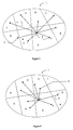
- a web 1 is notionally divided into M (arbitrary) geographical regions of roughly similar populations where M is the maximum valence of a node, i.e. M is the maximum number of links 3 which can be supported by a node 2. In the example shown, M is eight. In practice, any such geographical division will have to take account of lines-of-sight available. (Note that other nodes 2 in the web 1 and their connections have been omitted from Figures 3 and 4 for clarity.)
- region A in Figure 3 it can be seen that the node q in region A has been connected by a link 3 to other nodes 2 such that no more than one connection has been made to a node 2 lying in the same region. Connecting all the nodes 2 in this way will clearly ensure that webs 1 having nearest neighbour connections only are avoided. Stronger forms of this method are possible. For example, connections may be made as above, but which exclude any connection to a node 2 (such as node p) in the same region. In practice, the exact form of strategy adopted will depend on the geography and the ultimate range of a node 2. Another variant of the above scheme, which could be used where node range was restricted, would be to connect only to neighbouring regions, within range, as shown in Figure 4.
- the network is a non-nearest neighbour web, and, as a worst case, that the data a node is sinking/sourcing is being exchanged with the most distant node in the network. Since the number of nodes in a web is N, and if each node is sending data to one other node, then there are N connections active. For this web, assume that there are n hops on average between a node and the most distant node from it.
- the subscriber traffic therefore requires nBN units of bandwidth from the network.
- the web has E links each of which can carry 2b units of data (b in each direction), the network therefore has 2bE units of bandwidth available.
- 2bE nBN.
- each link carries traffic of bandwidth nBN/2E. If b ⁇ B, then nBN/2E ⁇ B, or nN/2E ⁇ 1, so that: n ⁇ 2E/N
- link bandwidth constraint (1) implies a constraint on the mean number of hops across the web (2) in terms of the number of nodes and links comprising the web in that from the point of view of desirable bandwidth properties, the quantity 2E/N should be of the order of the mean number of hops across the web.
- n should be as small as possible for real-time services, as large n means larger transit delays.
- E/N is related to the number of loops possible in the web, this should be as large as possible to exploit the desirable properties outlined above. In practice, a compromise value must be found.
- a symmetry argument together with a simple conceptual routing algorithm for the web may be used.
- One simple routing algorithm specifies that traffic going from one node to a second node will be split evenly at each intermediary node over each of the links leading further towards the destination. This could be done by, for example, a simple statistical multiplexing scheme. Thus for the first half of the journey the traffic is smeared out over the web, and for the second half the traffic concentrates towards the destination node. If only a single connection were active, then with this algorithm the traffic density would be higher around the two terminal nodes and sparser between them. When all the connections are active, the contributions to traffic density will tend to average out, depending on the web symmetry.
- the topology be as symmetric as possible.
- N nodes could be interconnected with links of bandwidth B using only a radio spectrum of B Hz (using the simplifying assumption of one bit per hertz). In fact, for practical reasons, this cannot be easily achieved (and this is discussed in detail later), but this property is extremely important as it shows that this structure is fundamentally very much more spectrally efficient than the cellular architecture, as will be discussed further below.
- FIG. 5 A simple practical example of a network or web system 1 according to the present invention is shown in Figure 5.
- the system 1 is connected via interconnect trunks 4 which connect specified nodes 2 to a trunk network 5.
- Each node 2 has a radio transceiver unit which is able to transmit and receive high radio frequency signals, for example at least 1 gigahertz (GHz) or 2.4 GHz or 4 GHz or even up to or greater than 40 GHz.
- the transceiver unit of each node 2 is in direct line-of-sight contact with four other similar units at other respective nodes 2 by direct line-of-sight links 3.
- each node 2 in this example of the system 1 be connected to the same number n of other nodes in a hypercube topology. This results in efficient use of the system 1. However, it is possible for some nodes in the system 1 to be connected to less than n other nodes in a less-than-perfect hypercube.
- a message from any one particular node 2 to any other particular node 2 will usually traverse several links 3 between several nodes 2 in a series of "hops" across the system 1.
- Each passage of a signal through a node 2 produces a delay in transfer of the signal. The delay might be only a millisecond or so, but if there were a very large number of nodes, this delay could rapidly build into significant fractions of a second. Such relatively long delays would not be generally acceptable in interactive services such as voice traffic, video conferencing, etc.
- the hypercube structure provides an efficient way of connecting many users with a small number of maximum hops required to transfer a signal between a source node and a destination node.
- each link 3 has a certain fixed information carrying capacity, determined in large part in practice by the bandwidth of the carrier signal used to transmit information between nodes 2.
- Each link 3 carries information data intended for a node connected to the link 3 and also "transit" data intended for other nodes. Indeed, each link 3 carries approximately n times the amount of transit data for each information data carried by the link.
- it is generally better to have a relatively small number of links 3 between nodes 2 i.e. a small dimension topology because this increases the bandwidth available to each message as fewer messages in total have to be carried by each link 3.
- the maximum number of nodes in such a system which is equivalent to the maximum number N of users of the system, is 2 n where there is just one subscriber per node 2.
- the maximum number of hops required to transmit information from any node to any other is n.
- n possible topologically equivalent routes for information to cross the system, meaning that good service can be maintained for the vast majority of users even if one or more individual nodes fails for some reason as other routes for messages to cross the system can be found.
- n 16.
- each user node needs to be connected to 16 other user nodes and a maximum of 16 hops are required to transmit information from any one node to any other node in the system.
- Topologies having a high degree of node interconnectivity support many possible equivalent routes through the system 1, each having a relatively low number of hops.
- Node complexity in terms of the number of links 3 required by each node 2, scales only very slowly with the size of the system 1 in a topology such as a hypercube topology.
- the ratio of user bandwidth to the resultant link bandwidth is low, possibly less than unity because of the multiple routing possibilities.
- Nodes 2 can be low cost because of the modest bandwidth requirements.
- the nodes 2 can be identical, leading to low installation costs and ease of operation, management and maintenance.
- the factors which will decide the optimum topology to be used include message traffic patterns, geography of the land in which the system is implemented, user location density, and system application (e.g. video-on-demand or Internet web-browsing).
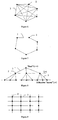
- topology is a fully interconnected topology shown by way of example in Figure 6.
- Each node 2 is connected to each other node 2 and thus for an N node network, each node 2 must support (N-1) external links 3 to other nodes 2.
- the total number of links 3 is therefore N(N-1)/2.
- This topology is most suited to a relatively small number of nodes 2, for example where N is less than 10.
- Adding nodes 2 to such a system 1 means that all existing nodes 2 must be modified to interconnect to any new node 2.
- the main advantage of such as system 1 is that only one hop is required to transfer a message from any one node 2 to any other node 2.
- a fully interconnected topology is most suited for connecting a small fixed number of nodes 2.
- FIG. 7 Another alternative topology is a linear chain topology shown by way of example in Figure 7.
- Each node 2 is connected to two others.
- N nodes 2 there are thus N links 3 and information will require N/2 hops to cross the system 1.
- each link 3 must be of high bandwidth (approximately N/2 times the bandwidth required by each node 2), which may limit the number of nodes which can be connected in such a topology.
- a main advantage of such a topology is the comparative simplicity of the nodes 2 which each have only two external links 3.
- a further example of a suitable topology is a tree topology as shown by way of example in Figure 8.
- every node 2 is connected to a fixed number of other nodes 2 in such a way that there are no "loops", i.e. there are no paths which can be followed which pass through the same node 2 more than once.
- the number of nodes 2 is the geometric series: which for large J tends to J L .
- a disadvantage of this topology is that at each hop away from a node 2, the nodes 2 must service J times the peak bandwidth of the node connection, implying greatly increased bandwidth requirements on descending the tree.
- Another disadvantage is that the nodes 2 differ between levels as they must function differently meaning that a system provider must deploy and manage different nodes for each level.
- an advantage is that at most two hops are required to transmit a message from any node 2 to any other node 2 in the same level (for example, the lowest level in Figure 8).
- An inhomogeneous tree topology relaxes the requirement for the number of connected lower nodes 2 to be fixed, though in other respects is similar to the homogeneous tree topology described above.
- a yet further example of a suitable topology for connecting the nodes 2 is a lattice topology shown by way of example in Figure 9.
- Nodes 2 are connected in an arbitrary manner to up to a fixed number n of nearest nodes 2.
- the bandwidth requirements of each link 3 may be high as it will be approximately ( ⁇ N)/2 times the bandwidth required by each user.
- the network 1 may effectively be a mixture of topologies.
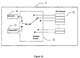
- antennas which are steerable either electrically or physically and which can point in any azimuthal direction, or an array of fixed antennas each pointing in a different direction such that any particular direction is accessible from one of the antennas.
- M The exact number M of antennas must be chosen to allow complete angular coverage without adversely affecting link gain. Note, M may be greater than n, the maximum active links per node. However, rather than providing M pairs of transceivers at each node, each pair being continuously connected to a single antenna, for cost reasons it is preferred to use only one transceiver per node and make use of time division multiplexing (TDM) and time division duplex (TDD) techniques to connect the transceiver to an antenna. A node therefore has only one transceiver pair which must be able to use all M antennas. TDM can be used to time-share the antennas with the transceiver.
- TDM time division multiplexing
- TDD time division duplex
- TDD can be used to alternate the receive/transmit operation of the node radio so that it is never receiving and transmitting simultaneously.
- Frequency division multiplexing or code-division multiplexing could be used as alternatives to TDM.
- Frequency division duplex could be used as an alternative to TDD. Other alternative schemes may be possible.
- a receiver 10 and transmitter 11 are alternatively connected to an M-way switch 12 which conducts radio-frequency (RF) power from and to the antennas 13.
- RF radio-frequency
- Time is divided equally into "frames" 20 and each frame 20 is divided equally into a transmit phase 21 and a receive phase 22.
- the transmit and receive phases 21,22 are themselves divided into equal time slots 23.
- Each one of these time slots 23 is used for one link 3 from a node 2.
- the node 2 transmits in one time slot 23 on one link 3 then the next time slot 23 on the next link 3 and so on, followed by receiving in one time slot 23 on one link 3 and the next time slot 23 on the next link 3 and so on.
- Each receive time slot 23 of each node is arranged to be long enough to ensure that there is sufficient time for a signal transmitted from other nodes 2 to travel to the node 2 in question and also to be received in full at the node 2 in question, particularly to ensure that the data packet and any guard bands are received.
- In-turn sequencing is not the only possible way of addressing antennas 13.
- the total bandwidth available at a node 2 can be partitioned by allocating more or fewer time slots 23 to an antenna 13, within a receive or transmit half frame 21,22. This is illustrated in the matrices in Figure 12.
- the columns of the matrices represent the eight antennas 13 on an example node 2, and the rows eight possible receive/transmit time slots 23.
- a '1' in a cell indicates which antenna 13 is active during which time slot 23.
- a '-' in a cell indicates no activity of an antenna 13 in a particular time slot 23. The number of '1's must not exceed the total number of time slots 23 available.
- each antenna has a time slot, so each link can carry 1 unit of bandwidth.
- antenna A0 has two time slots allocated, and hence can carry two units of bandwidth.
- Antennas A1, A2, and A7 each have one time slot allocated, and antenna A4 has three time slots allocated.
- Antennas A3, A5, and A6 have no allocated time slots and hence are idle.
- Figure 12C all the time slots have been given to antenna A4. This means that link associated with antenna A4 can carry eight units of bandwidth whilst all the others are idle.
- nodes A and B must both be using the same time slot for the link 3 between them, say time slot 1 transmit for A and time slot 1 receive for B.
- a and C must use the same time slot for the link between them, say time slot 2, etc.
- each node 2 may only use each time slot once. In the preferred embodiment, this requirement is met exactly throughout the network.
- each link 3 in the network 1 is assigned a time slot number such that no node 2 has more than one link of the same time slot number. In addition, it is desirable to minimise the total number of time slots required.
- different groups of nodes 2 may be communicating with each other at any one time.
- different transmission paths in the system 1 may be active and carrying traffic at any one time.
- the set of channels should be as small as necessary. This requirement for a minimum number of frequency channels is related to the beam width of the node antenna. For large widths, the area of the interference zone PDQ in Figure 14 is also large and hence there is a greater likelihood of nodes such as G and H lying in it. Similarly, for small beam widths, the zone area is small, thus containing fewer nodes.
- the radio system must be frequency-agile, re-tuning to a different pre-allocated channel on each time slot.
- Link loss occurs on several timescales. In the medium term, a temporary loss for some seconds or minutes may be caused by large vehicles moving nearby, or perhaps a plume of smoke from a fire. The network will cope with these by re-routing traffic to avoid the problem areas until the link recovers. On a longer timescale, a link 3 may be lost because line of sight is being permanently obstructed. This may be caused by new building or tree growth. These losses should be handled at a network planning level. As a background activity, the network may constantly monitor all available lines of sight, (i.e. links 3 between nodes),including those which are not currently being used for subscriber traffic. On a timescale of hours and days, or even minutes or seconds, the network can be automatically reconfigured to use different subsets of the available lines of sight to optimise operational parameters.
- each path carries a duplicate of the subscriber data, so that the receiving node 2 may accept data from any active path. This uses up m times the basic subscriber bandwidth (B) for the connection, but is simple to implement.
- the second example of method of operation can be extended to protect against multiple path failures but is more complex than the first example of method of operation.
- one time slot 23 is used to support all of the bandwidth on a link 3. This maximises the raw data transfer rate; however, it is always important to maintain spectral efficiency.
- the present invention requires approximately n.B link .F web units of bandwidth, where:
- F cell is typically in the range 6 to 10 and computer modelling has shown F web to be much the same.
- the relative efficiency is 25 fold. This is extremely important as there are many demands on radio bandwidth and as a matter of practice the regulatory and licensing authorities are only able to license relatively narrow regions of the radio spectrum.
- the present invention places much lower demands on the radio spectrum than a cellular system providing a comparable user bandwidth.
- the system 1 is well suited to the use of asynchronous transfer mode (ATM) technology which can support connection oriented (circuit switched) or connectionless (packet switched) traffic modes by the transfer of 53 byte information "cells".
- ATM asynchronous transfer mode
- each out-going connection can be labelled with an index (0...n-1).
- a path through the network system 1 can then be defined by a list of such indices. As will be understood from the above, the maximum length of this list will be n entries.
- an information packet can be defined to be of type Message which has two components:
- the routing address is the absolute address of a node 2 in the network system 1.
- Each node 2 will have access to its own address (my_L in the code discussed below). To see how addressing works in such a system 1, consider the addressing of points on a simple unit 3-cube shown in Figure 15.
- Each node 2 has a labelled set of channels which can be thought of as Cartesian axes, in this case X, Y and Z. Thus each node 2 has an X-channel, a Y-channel and a Z-channel.
- the address (L) of a node 2 in a 3-cube geometry is one of the eight 3-vectors: (0,0,0), (1,0,0), ... (1,1,1).
- a move through the cube by one hop along a link 3 is represented by the following relationship between the initial (L1) and final (L2) address:
- 1
- the function of the handleReturnedMessage function is to take appropriate action with a returned message. This strategy will depend on the type of data service supported. It could be one of the following:
- the procedure SendPacket (msg, next_node) conceptually sends Message msg to the outgoing link 3 with index next_node.
- the procedure ProcessCell (cell) is responsible for consuming the information cell locally and making it available to the user.
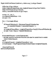
- the decideNextChannel function has a functionality which is network topology specific. For the case of a hypercube topology, an example of this is set out in Figure 17, where ActiveChannels is the number of currently configured channels on a node 2 (which may vary for each node 2 in the system), and MaximumChannelUtilisation is the value at and above which the outgoing channel may be considered to be at full capacity and can therefore accept no further traffic.
- an output channel is a measure of the traffic loading of that channel over an immediately previous period of time.
- a measure of traffic loading might be one, or a combination of, the following factors:
- ChannelUtilisation function may be used to control non-existent links as in the case of a partially complete hypercube.
- link utilisation could be set permanently to MaximumChannelUtilisation.
- a continuously operating function of a node would be the monitoring of this loading and allow the routing software to obtain a value related to the current loading for a given link. This is what the function ChannelUtilisation (channel) does.
- MapWeightedChannelToBestChanne1 translates the input weighted channel index into a real output channel for the node.
- output channels are denoted by integer values, 0 to 7 for example, and the mapping of the real weighted channel number to this is simply a rounding operation. For example, weighted channel value 6.7152 is mapped to channel index 7.
- the performance of the system 1 has been primarily described so far in terms of its ability to move data within a cluster of nodes 2. However, for many types of service it is required to connect into a trunk network 5, as indicated in Figure 5. For example, in a network of say 250 users used primarily for 5 Mbps video-on-demand (VOD) service with a loading of say 0.3 Erlang per user, the total bandwidth required from the trunk network is 375Mbps, assuming that no source material migration takes place. As the maximum input rate to a node will be say about 40Mbps (assuming eight links 3 of maximum 5Mbps each per node 2), this 375 Mbit/s of traffic will need to be groomed onto the trunk network at at least ten locations. This can be done in two ways.
- VOD video-on-demand
- the first alternative is to connect the subscriber interface of a node 2' at each of the "input" locations to a suitable interface on the trunk network 5 (e.g. DS3, STMO, 1) as shown in Figure 18.
- the nodes 2' at the input locations can be connected by an optical fibre 4 to the fibre backbone of the trunk network 5 for example.
- These input locations can be chosen for network deployment convenience rather than by subscriber location. This is much easier than running fibre to cellular type base stations where the positions of the base stations are dictated by the cellular structure.
- the second alternative is to configure a set of nodes 2" so that all time slots 23 are used on one link.
- This provides several point to point connections with exactly the right bandwidth (40Mbps) for connection into a node 2.
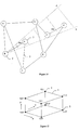
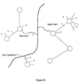
- the specially configured nodes 2" can be connected by a suitable data connection 6 to a normal subscriber node 2 at the same location. It should be noted that these specially configured nodes 2" can use exactly the same hardware as the normal subscriber nodes 2. However, the specially configured nodes 2" could each use a high gain, long range movable antenna if required. Such antennas could be directed at a cluster 7 of suitably configured nodes 8, located at a single trunk access point 9 as shown in Figure 19.
- a problem with many radio communications systems is multipathing. This can occur when a receiver receives a main signal received directly from a transmitter but also receives signals from the transmitter which have been reflected from buildings or moving vehicles, for example. The reflected signal is delayed relative to the main signal, which can lead to cancellation of the main signal if the reflected signal is an odd number of half wavelengths lagging in phase.
- cancellation is not much of a problem; the user can usually find a position for the receiver where cancellation because of reflections from buildings does not occur or, where cancellation occurs because of a signal reflected from a moving vehicle, the cancellation only occurs briefly and the vehicle moves away, thereby removing the problem.
- objects moving past a receiver can cause frequent cancellation of the main signal by virtue of those moving objects regularly and frequently reflecting signals which lag the main signal by an odd number of half wavelengths.
- the antennas of the transmitters and receivers in each node 2 be highly directional.
- a highly directional transmitter/receiver With a highly directional transmitter/receiver, there tends to be better gain and therefore better signal strength than with an isotropic antenna.
- a highly directional transmitter/receiver tend naturally to detect only the main signal coming along the line-of-sight link 3 to the node 2 and does not detect reflected signals which approach the node at an angle to the main signal, a highly directional transmitter/receiver has improved operating characteristics by virtue of the higher gain available.
- circular polarisation of the transmitted radiation can be used to provide additional protection against loss of signal due to multi-path effects.
- a radio wave On being reflected from a surface, a radio wave suffers a change in its phase relative to the incoming wave. If this incoming wave is right-hand circularly polarised, for example, then on reflection, this polarisation will be reversed to left-hand circular polarisation. In this way, unwanted reflected radiation is rejected relative to directly transmitted radiation if the receiver is selective to purely right-hand circularly polarised radio waves.
- the system 1 uses line-of-sight, highly directional, high gain, high frequency transmitters/ receivers equipped to emit and detect circularly polarised radiation.
- the system 1 of the present invention no base transmitter station is required and the system 1 can be constructed from a single type of identical transceiver unit at each node 2.
- the network system 1 is potentially very much easier and cheaper to build, deploy and maintain in comparison with a cellular system which uses base stations. There is no burying or suspending of cables or wires or erecting of many large base-station antenna masts, again representing a large saving in costs and also minimising the environmental impact of the system 1.
- the capacity of the system 1 is very large as there are many possible routes between nodes 2 and to the edge of the system 1. Failure of a particular node 2 accordingly implies loss of service for only one user and other users are not normally affected as alternative paths can be found for transmission of a signal. Because each node 2 is concerned with switching as well as the transmission of information traffic, the whole system 1 effectively behaves as a distributed switch. This means that conventional access switches, which represent significant capital expenditure, can be eliminated.
- the present invention allows an operator to begin operating a communications system 1 having very high data transfer rates to a small number of users at relatively low cost.
- 128 nodes can be set up in a system as described above at very low cost compared, for example, to equivalent cable and cellular solutions.
- Subscribers to the system can be allocated respective nodes 2.
- the remaining nodes 2 which have not been allocated to a user can be used as "strategic" nodes 2 solely for carrying information traffic between user nodes 2.
- the strategic nodes can be allocated to the new users.
- new nodes can be added and the system 1 as a whole can be reconfigured to introduce the new nodes to the system. If necessary, a similar process in reverse can be applied to remove nodes which are no longer required or which are in maintenance or have failed, for example.
- the maximum bandwidth which may be delivered to a node user from the network side (Bdown) and the maximum bandwidth a user may deliver to the network (Bup) may be independently configured dynamically by the network operator without affecting the capacity of the node for transit traffic.
- a low tariff service might be Bup « Bdown (similarly to ADSL service)
- Bup and Bdown must be less than the peak user data rate allowed by the radio system.
- a link 3 between two nodes 2 may actually comprise two or more parallel radio channels, i.e. the link 3 uses simultaneously two or more frequency channels, thus reducing the bandwidth load on a particular radio channel.
- the overall control of routing of the signals between nodes can be by virtue of a central controller.
- the central controller might perform a periodic (e.g. daily) check on the system 1 as a whole to determine whether any nodes 2 have failed.
- the central controller 1 can then determine which route should be followed by a message from any one node 2 to any other node 2 in the system 1. Appropriate instructions could then be sent from the central controller to each node 2 so that each node 2 applies an appropriate address to each information packet.
- the present invention allows very high data transfer rates to be achieved. For example, as mentioned, a total node data transfer rate of 40Mbps is entirely feasible. Data transmission rates of 5Mbps with burst rates of 25Mbps can be achieved with ease.
- a communications system comprises: a plurality of nodes, each node having: receiving means for receiving a signal transmitted by wireless transmitting means; transmitting means for wireless transmission of a signal; and, means for determining if a signal received by said node includes information for another node and causing a signal including said information to be transmitted by said transmitting means to another node if said signal includes information for another node; each node having one or more substantially unidirectional point-to-point wireless transmission links, each of said links being to one other node only.
- the nodes may be linked so as to form transmission path loops thereby to provide plural choices of path for the transmission of a signal between at least some of the nodes. Each loop may consist of an even number of links.
- At least some of the nodes may have plural links to other nodes, each of said plural links between respective pairs of nodes being associated with a time slot.
- Each link for each node may be associated with a distinct time slot.
- the allocation of time slots to the links can be varied such that a link may selectively be associated with more than one time slot.
- a communications system comprises: a plurality of nodes, each node having: receiving means for receiving a signal transmitted by wireless transmitting means; transmitting means for wireless transmission of a signal; and, means for determining if a signal received by said node includes information for another node and causing a signal including said information to be transmitted by said transmitting means to another node if said signal includes information for another node; each node having a point-to-point link with at least one other node such that each node can transmit a signal to at least one other node, each link between respective pairs of nodes being associated with a distinct time slot, the nodes being linked so as to form transmission path loops thereby to provide plural choices of path for the transmission of a signal between at least some of the nodes, each loop consisting of an even number of links. At least some of the nodes may have plural links to other nodes, each of said plural links between respective pairs of nodes being associated with a time slot.
- Each node may have a direct line-of-sight link with at least one other node such that each node can transmit a signal to another node in line-of-sight with said each node.
- Each node may comprise means for transmitting a signal including said information to another node if and only if a signal received at said node includes information for another node.
- each node is stationary.
- the number of nodes is preferably less than the number of links.
- Each node may be arranged to be in a transmission mode for a time period which alternates with a time period for a reception mode. At least one node may be arranged not to transmit to any other node information in a signal received by said at least one node when that information is addressed to said at least one node.
- each node is arranged not to transmit to any other node information in a signal received by said at least one node when that information is addressed to said at least one node.
- Each node may have addressing means for adding to information in a received signal the address of a node to which a signal including said information is to be routed when said information is for another node.
- the addressing means may include means for determining the route of information through the system and adding an appropriate address to the information accordingly.
- a central system controller may be provided for determining the route of information through the system.
- At least one node may have means for determining if a received signal includes information for said at least one node and processing means for processing information in a signal addressed to said at least one node.
- the transmitting means of the nodes may be arranged to transmit signals at frequencies greater than about 1 GHz.
- the link between two nodes may be arranged to use simultaneously two or more frequency channels.
- Said receiving and transmitting means may be arranged to transmit and detect circularly polarised radiation.
- the transmitting means may include a highly directional transmitter.
- the receiving means may include a highly directional receiver.
- Each node is preferably substantially identical.
- the system may be connected to a conventional trunk network for providing access to other networks.
- a further node may be connected by a data connection to one of the nodes of the system and arranged to transfer a signal to and/or receive a signal from the trunk network.
- a data storage server may be connected to or provided at a node.
- At least one link of a node may be arranged to use a first transmission frequency and at least one other link of said node is arranged to use a second transmission frequency.
- Some of the nodes may be allocated to subscribers and some of the nodes may not be allocated to subscribers, at least some of said non-allocated nodes being solely for carrying information traffic between subscriber nodes.
- a method of communications comprises the steps of: (A) transmitting a signal from one node to another node along a substantially unidirectional point-to-point wireless transmission link between said nodes; (B) receiving said signal at said other node; (C) determining in said other node if the signal received by said other node includes information for a further node and transmitting a signal including said information from said other node to a further node along a substantially unidirectional point-to-point wireless transmission link between said nodes if said signal includes information for a further node; and, (D) repeating steps (A) to (C) until said signal reaches its destination node.
- At least some of the nodes may have plural links to other nodes, each of said plural links between respective pairs of nodes being associated with a time slot, and each transmission step on a link of said one node occurring during a distinct time slot and each receiving step on a link of said other node occurring during a distinct time slot.
- Each node may add to information in a received signal the address of a node to which a signal including said information is to be routed when said information is for another node.
- Each node may have addressing means, the addressing means determining the route of the information through the system and adding an appropriate address to the information accordingly.
- a central system controller may determine the route of information through the system.
- Each node may transmit a signal including said information to another node if and only if a signal received at said node includes information for another node.
- the method may include the steps of determining in at least one node if a received signal includes information for said at least one node and processing the information in a signal addressed to said at least one node.
- the signals may be transmitted at frequencies greater than about 1 GHz.
- There may be at least two possible paths for transfer of data between a source node and a destination node, the method then optionally comprising the step of transmitting a copy of said data on each of said at least two paths.
- the method then optionally comprising the steps of transmitting from the source node a part only of said data on each of said at least two paths and reconstructing the data from said transmitted parts of said data in the destination node.
- telecommunications switching comprising a communications system as described above.
Applications Claiming Priority (5)
| Application Number | Priority Date | Filing Date | Title |
|---|---|---|---|
| GB9626210 | 1996-12-18 | ||
| GBGB9626210.0A GB9626210D0 (en) | 1996-12-18 | 1996-12-18 | Communications system |
| GBGB9720152.9A GB9720152D0 (en) | 1996-12-18 | 1997-09-22 | Communications system and method |
| GB9720152 | 1997-09-22 | ||
| EP97950262A EP0947077B1 (de) | 1996-12-18 | 1997-12-18 | Kommunikationssystem und -verfahren |
Related Parent Applications (1)
| Application Number | Title | Priority Date | Filing Date |
|---|---|---|---|
| EP97950262A Division EP0947077B1 (de) | 1996-12-18 | 1997-12-18 | Kommunikationssystem und -verfahren |
Publications (2)
| Publication Number | Publication Date |
|---|---|
| EP1085708A2 true EP1085708A2 (de) | 2001-03-21 |
| EP1085708A3 EP1085708A3 (de) | 2009-04-29 |
Family
ID=26310660
Family Applications (4)
| Application Number | Title | Priority Date | Filing Date |
|---|---|---|---|
| EP00125419A Withdrawn EP1094642A2 (de) | 1996-12-18 | 1997-12-18 | Kommunikationssystem und -verfahren |
| EP00125417A Withdrawn EP1085707A2 (de) | 1996-12-18 | 1997-12-18 | Kommunikationssystem und Verfahren |
| EP97950262A Revoked EP0947077B1 (de) | 1996-12-18 | 1997-12-18 | Kommunikationssystem und -verfahren |
| EP00125418A Withdrawn EP1085708A3 (de) | 1996-12-18 | 1997-12-18 | Kommunikationssystem und Verfahren |
Family Applications Before (3)
| Application Number | Title | Priority Date | Filing Date |
|---|---|---|---|
| EP00125419A Withdrawn EP1094642A2 (de) | 1996-12-18 | 1997-12-18 | Kommunikationssystem und -verfahren |
| EP00125417A Withdrawn EP1085707A2 (de) | 1996-12-18 | 1997-12-18 | Kommunikationssystem und Verfahren |
| EP97950262A Revoked EP0947077B1 (de) | 1996-12-18 | 1997-12-18 | Kommunikationssystem und -verfahren |
Country Status (12)
| Country | Link |
|---|---|
| US (5) | US6553020B1 (de) |
| EP (4) | EP1094642A2 (de) |
| JP (1) | JP2001506825A (de) |
| CN (1) | CN1134139C (de) |
| AU (1) | AU5328698A (de) |
| BR (1) | BR9713966A (de) |
| CA (1) | CA2275282C (de) |
| DE (1) | DE69730238T2 (de) |
| GB (2) | GB9720152D0 (de) |
| HK (1) | HK1022391A1 (de) |
| RU (1) | RU2222869C2 (de) |
| WO (1) | WO1998027694A1 (de) |
Cited By (1)
| Publication number | Priority date | Publication date | Assignee | Title |
|---|---|---|---|---|
| RU2516623C1 (ru) * | 2010-08-16 | 2014-05-20 | Хуавей Текнолоджиз Ко., Лтд. | Аппаратура беспроводной связи и способ самопроверки аппаратуры беспроводной связи |
Families Citing this family (171)
| Publication number | Priority date | Publication date | Assignee | Title |
|---|---|---|---|---|
| GB9812430D0 (en) * | 1998-06-09 | 1998-08-05 | Radiant Networks Plc | Data transfer method and apparatus |
| US6366584B1 (en) * | 1999-02-06 | 2002-04-02 | Triton Network Systems, Inc. | Commercial network based on point to point radios |
| JP3663323B2 (ja) * | 1999-04-05 | 2005-06-22 | シャープ株式会社 | ミリ波送信装置およびミリ波受信装置 |
| JP2000358036A (ja) * | 1999-06-15 | 2000-12-26 | Nec Corp | メッシュ型無線アクセスシステム |
| US6822951B1 (en) * | 1999-11-05 | 2004-11-23 | Texas Instruments Incorporated | Method and apparatus for routing messages in a wireless network |
| US6778505B1 (en) * | 2000-01-03 | 2004-08-17 | Agere Systems Inc. | DSL automatic protocol detection system |
| US20020163889A1 (en) * | 2000-02-02 | 2002-11-07 | Yechiam Yemini | Method and apparatus for providing services on a dynamically addressed network |
| FI114369B (fi) * | 2000-03-31 | 2004-09-30 | Keijo Laehetkangas | Tietoliikenneverkko |
| SE522377C2 (sv) * | 2000-03-31 | 2004-02-03 | Kvaser Consultant Ab | Anordning för att överföra data- och styrkommandon via radioförbindelser i distribuerat styrsystem för en eller flera maskiner och/eller processer |
| US7139262B1 (en) * | 2000-05-18 | 2006-11-21 | Bbn Technologies Corp. | Systems and methods for creating wireless small world networks |
| US7142520B1 (en) * | 2000-06-16 | 2006-11-28 | Nokia Mobile Phones Ltd. | Method and apparatus for mobile internet protocol regional paging |
| US6714966B1 (en) * | 2000-07-31 | 2004-03-30 | The Boeing Company | Information delivery service |
| US6732147B1 (en) | 2000-07-31 | 2004-05-04 | The Boeing Company | Leaving a broadcast channel |
| US6920497B1 (en) | 2000-07-31 | 2005-07-19 | The Boeing Company | Contacting a broadcast channel |
| US6701344B1 (en) * | 2000-07-31 | 2004-03-02 | The Boeing Company | Distributed game environment |
| US6910069B1 (en) * | 2000-07-31 | 2005-06-21 | The Boeing Company | Joining a broadcast channel |
| CN1218543C (zh) * | 2000-10-10 | 2005-09-07 | 辐射网络公司 | 通信格网 |
| US6813497B2 (en) * | 2000-10-20 | 2004-11-02 | Leap Wirelesss International | Method for providing wireless communication services and network and system for delivering same |
| US6850502B1 (en) * | 2000-10-30 | 2005-02-01 | Radiant Networks, Plc | Join process method for admitting a node to a wireless mesh network |
| GB0030932D0 (en) | 2000-12-19 | 2001-01-31 | Radiant Networks Plc | Antenna apparatus, communications apparatus and method of transmission |
| US6990316B2 (en) | 2001-06-26 | 2006-01-24 | Nokia Corporation | Short range RF network configuration |
| WO2003003672A2 (en) | 2001-06-28 | 2003-01-09 | King's College London | Electronic data communication system |
| EP1410581B1 (de) * | 2001-07-20 | 2009-05-13 | Intel Corporation | Vermaschte netzwerke |
| JP2003092578A (ja) * | 2001-09-18 | 2003-03-28 | Fujitsu Ltd | 管理装置、処理装置、装置、およびプログラム |
| US7054867B2 (en) * | 2001-09-18 | 2006-05-30 | Skyris Networks, Inc. | Systems, methods and programming for routing and indexing globally addressable objects and associated business models |
| KR100434049B1 (ko) * | 2001-10-16 | 2004-06-04 | 엘지전자 주식회사 | Vod 서비스 시스템의 데이터 전송속도 변경방법 |
| US6901064B2 (en) * | 2002-01-10 | 2005-05-31 | Harris Corporation | Method and device for establishing communication links and detecting interference between mobile nodes in a communication system |
| US6831921B2 (en) | 2002-03-27 | 2004-12-14 | James A. Higgins | Wireless internet access system |
| US20050201342A1 (en) * | 2002-03-27 | 2005-09-15 | Randy Wilkinson | Wireless access point network and management protocol |
| US7164667B2 (en) * | 2002-06-28 | 2007-01-16 | Belair Networks Inc. | Integrated wireless distribution and mesh backhaul networks |
| US7366519B2 (en) * | 2002-10-21 | 2008-04-29 | Hong Kong Applied Science And Technology Research Institute Co., Ltd. | Systems and methods for managing wireless communications using link space information |
| US7359945B2 (en) * | 2002-12-05 | 2008-04-15 | Microsoft Corporation | Using conditional statements in electronic messages to prevent overuse of resources or time when delivering the electronic message |
| US8526490B2 (en) | 2002-12-10 | 2013-09-03 | Ol2, Inc. | System and method for video compression using feedback including data related to the successful receipt of video content |
| US7849491B2 (en) | 2002-12-10 | 2010-12-07 | Onlive, Inc. | Apparatus and method for wireless video gaming |
| US9314691B2 (en) | 2002-12-10 | 2016-04-19 | Sony Computer Entertainment America Llc | System and method for compressing video frames or portions thereof based on feedback information from a client device |
| US8366552B2 (en) | 2002-12-10 | 2013-02-05 | Ol2, Inc. | System and method for multi-stream video compression |
| US7493078B2 (en) | 2002-12-10 | 2009-02-17 | Onlive, Inc. | Antenna assembly for satellite and wireless services |
| US8711923B2 (en) | 2002-12-10 | 2014-04-29 | Ol2, Inc. | System and method for selecting a video encoding format based on feedback data |
| US9108107B2 (en) | 2002-12-10 | 2015-08-18 | Sony Computer Entertainment America Llc | Hosting and broadcasting virtual events using streaming interactive video |
| US7558525B2 (en) | 2002-12-10 | 2009-07-07 | Onlive, Inc. | Mass storage repository for a wireless network |
| US9446305B2 (en) | 2002-12-10 | 2016-09-20 | Sony Interactive Entertainment America Llc | System and method for improving the graphics performance of hosted applications |
| US8964830B2 (en) | 2002-12-10 | 2015-02-24 | Ol2, Inc. | System and method for multi-stream video compression using multiple encoding formats |
| US9192859B2 (en) | 2002-12-10 | 2015-11-24 | Sony Computer Entertainment America Llc | System and method for compressing video based on latency measurements and other feedback |
| US9138644B2 (en) | 2002-12-10 | 2015-09-22 | Sony Computer Entertainment America Llc | System and method for accelerated machine switching |
| US9077991B2 (en) | 2002-12-10 | 2015-07-07 | Sony Computer Entertainment America Llc | System and method for utilizing forward error correction with video compression |
| US8549574B2 (en) | 2002-12-10 | 2013-10-01 | Ol2, Inc. | Method of combining linear content and interactive content compressed together as streaming interactive video |
| US20090118019A1 (en) | 2002-12-10 | 2009-05-07 | Onlive, Inc. | System for streaming databases serving real-time applications used through streaming interactive video |
| US7684752B2 (en) | 2002-12-10 | 2010-03-23 | Onlive, Inc. | Wireless network providing distributed video / data services |
| US9061207B2 (en) | 2002-12-10 | 2015-06-23 | Sony Computer Entertainment America Llc | Temporary decoder apparatus and method |
| US10201760B2 (en) | 2002-12-10 | 2019-02-12 | Sony Interactive Entertainment America Llc | System and method for compressing video based on detected intraframe motion |
| US7162258B2 (en) * | 2003-01-15 | 2007-01-09 | Symbol Technologies, Inc. | Light fixture wireless access points |
| US7437640B2 (en) * | 2003-02-13 | 2008-10-14 | Janusz Rajski | Fault diagnosis of compressed test responses having one or more unknown states |
| US7590084B2 (en) | 2003-02-14 | 2009-09-15 | Onlive, Inc. | Self-configuring, adaptive, three-dimensional, wireless network |
| US7215660B2 (en) | 2003-02-14 | 2007-05-08 | Rearden Llc | Single transceiver architecture for a wireless network |
| US7593361B2 (en) | 2003-02-14 | 2009-09-22 | Onlive, Inc. | Method of operation for a three-dimensional, wireless network |
| US20060171402A1 (en) * | 2003-03-06 | 2006-08-03 | Moore John A | Method and system for providing broadband multimedia services |
| US20040174900A1 (en) * | 2003-03-06 | 2004-09-09 | Incucomm, Inc. A Delaware Corporation | Method and system for providing broadband multimedia services |
| US8098637B1 (en) * | 2003-03-28 | 2012-01-17 | Regents Of The University Of Minnesota | Load balancing in wireless local area networks |
| MXPA05011578A (es) | 2003-04-28 | 2006-07-06 | Alcatel Ip Networks Inc | Mensajeria por eco que verifica la via de distribucion de red basada por servicio. |
| US20050036470A1 (en) * | 2003-08-04 | 2005-02-17 | Calvert Nathan Hunter | Multi-hop peer-to-peer wireless local loop phone system and method |
| US7065144B2 (en) * | 2003-08-27 | 2006-06-20 | Qualcomm Incorporated | Frequency-independent spatial processing for wideband MISO and MIMO systems |
| US8462817B2 (en) * | 2003-10-15 | 2013-06-11 | Qualcomm Incorporated | Method, apparatus, and system for multiplexing protocol data units |
| US9226308B2 (en) | 2003-10-15 | 2015-12-29 | Qualcomm Incorporated | Method, apparatus, and system for medium access control |
| US8842657B2 (en) | 2003-10-15 | 2014-09-23 | Qualcomm Incorporated | High speed media access control with legacy system interoperability |
| US8483105B2 (en) * | 2003-10-15 | 2013-07-09 | Qualcomm Incorporated | High speed media access control |
| US8233462B2 (en) | 2003-10-15 | 2012-07-31 | Qualcomm Incorporated | High speed media access control and direct link protocol |
| US8284752B2 (en) * | 2003-10-15 | 2012-10-09 | Qualcomm Incorporated | Method, apparatus, and system for medium access control |
| US8472473B2 (en) * | 2003-10-15 | 2013-06-25 | Qualcomm Incorporated | Wireless LAN protocol stack |
| ES2418364T3 (es) * | 2003-12-23 | 2013-08-13 | Telefonaktiebolaget Lm Ericsson (Publ) | Método y sistema para enrutamiento eficiente en redes Ad Hoc |
| CN1886941A (zh) * | 2003-12-23 | 2006-12-27 | 艾利森电话股份有限公司 | 预测性ad-hoc |
| WO2005062553A1 (en) * | 2003-12-23 | 2005-07-07 | Telefonaktiebolaget Lm Ericsson (Publ) | Method and system for routing traffic in ad hoc networks |
| KR20070007032A (ko) * | 2004-01-20 | 2007-01-12 | 엘지전자 주식회사 | 이동 애드 혹 네트워크 시스템 및 운용 방법 |
| US7818018B2 (en) * | 2004-01-29 | 2010-10-19 | Qualcomm Incorporated | Distributed hierarchical scheduling in an AD hoc network |
| US8903440B2 (en) * | 2004-01-29 | 2014-12-02 | Qualcomm Incorporated | Distributed hierarchical scheduling in an ad hoc network |
| US20050208949A1 (en) * | 2004-02-12 | 2005-09-22 | Chiueh Tzi-Cker | Centralized channel assignment and routing algorithms for multi-channel wireless mesh networks |
| US8315271B2 (en) * | 2004-03-26 | 2012-11-20 | Qualcomm Incorporated | Method and apparatus for an ad-hoc wireless communications system |
| JP2005294956A (ja) * | 2004-03-31 | 2005-10-20 | Mitsui Eng & Shipbuild Co Ltd | 分散データ収集システムおよび同システムの構築方法 |
| DE102004020288A1 (de) * | 2004-04-26 | 2005-11-17 | Siemens Ag | Verfahren zur Zuordnung einer Anzahl von M teilnehmerseitig angeordneten Datenverbindungen zu einer Anzahl von N transportseitig angeordneten Datenverbindungen |
| US7564814B2 (en) * | 2004-05-07 | 2009-07-21 | Qualcomm, Incorporated | Transmission mode and rate selection for a wireless communication system |
| US20050271128A1 (en) * | 2004-06-02 | 2005-12-08 | Williams Jeffery D | Distributed SCADA system for remote monitoring and control of access points utilizing an intelligent uninterruptible power supply system for a WISP network |
| US8401018B2 (en) * | 2004-06-02 | 2013-03-19 | Qualcomm Incorporated | Method and apparatus for scheduling in a wireless network |
| US8302164B2 (en) | 2004-07-22 | 2012-10-30 | Facebook, Inc. | Authorization and authentication based on an individual's social network |
| US7634067B1 (en) * | 2004-12-17 | 2009-12-15 | Verizon Data Services Llc | Methods and systems for visual voice calls |
| JP4506506B2 (ja) * | 2005-02-28 | 2010-07-21 | 沖電気工業株式会社 | 無線アクセス装置、および、通信制御方法 |
| US9264373B2 (en) * | 2005-07-01 | 2016-02-16 | Telefonaktiebolaget L M Ericsson (Publ) | Adaptive frame structure for TDD point-to-point wireless transmission |
| JP4662353B2 (ja) * | 2005-08-12 | 2011-03-30 | キヤノン株式会社 | 通信システム、通信装置、通信制御デバイス、制御プログラムおよび制御方法 |
| US8600336B2 (en) | 2005-09-12 | 2013-12-03 | Qualcomm Incorporated | Scheduling with reverse direction grant in wireless communication systems |
| CA2559182C (en) | 2005-09-12 | 2017-05-09 | Acuity Brands, Inc. | Network operation center for a light management system having networked intelligent luminaire managers |
| CA2624502C (en) | 2005-10-05 | 2013-07-09 | Guardian Networks, Llc | A method and system for remotely monitoring and controlling field devices with a street lamp elevated mesh network |
| US7894469B2 (en) * | 2005-10-20 | 2011-02-22 | Fujitsu Limited | Generic SONET/SDH time slot selection algorithm |
| US7583654B2 (en) * | 2005-12-28 | 2009-09-01 | Honeywell International Inc. | Sub-frame synchronized multiplexing |
| WO2007082011A2 (en) * | 2006-01-11 | 2007-07-19 | Fisher-Rosemount Systems, Inc. | Visual mapping of field device message routes in a wireless mesh network |
| US8576811B2 (en) * | 2006-02-06 | 2013-11-05 | Motorola Solutions, Inc. | System, method and apparatus for reliable exchange of information between nodes of a multi-hop wireless communication network |
| AU2007220157B2 (en) * | 2006-03-03 | 2011-06-09 | Koninklijke Philips Electronics N.V. | Clear channel reporting and assisting orphaned nodes in a wireless network |
| US20070209059A1 (en) * | 2006-03-03 | 2007-09-06 | Moore John A | Communication system employing a control layer architecture |
| WO2007110865A1 (en) * | 2006-03-27 | 2007-10-04 | Rayv Inc. | Realtime media distribution in a p2p network |
| US7719994B2 (en) * | 2006-04-26 | 2010-05-18 | Honeywell International Inc. | Sub-frame synchronized ranging |
| US7688747B2 (en) * | 2006-08-30 | 2010-03-30 | Honeywell International Inc. | Sub-frame synchronized residual ranging |
| WO2008037051A1 (en) | 2006-09-27 | 2008-04-03 | Dragonwave, Inc. | Wireless network communication apparatus, methods, and integrated antenna structures |
| ATE551816T1 (de) * | 2006-09-28 | 2012-04-15 | Rayv Inc | System und verfahren zum peer-to-peer-medien- streaming |
| EP2074717B1 (de) * | 2006-09-29 | 2019-05-15 | Rosemount, Inc. | Drahtloses mesh-netzwerk mit mehrfachgrössen-zeitschlitzen für die tdma-kommunikation |
| WO2008048130A1 (en) * | 2006-10-16 | 2008-04-24 | Freescale Semiconductor, Inc. | System and method for electromigration tolerant cell synthesis |
| US7515092B2 (en) * | 2007-01-17 | 2009-04-07 | Honeywell International Inc. | Sub-frame synchronized residual radar |
| US8032124B2 (en) | 2007-02-28 | 2011-10-04 | Microsoft Corporation | Health-related opportunistic networking |
| US8285259B2 (en) * | 2007-05-29 | 2012-10-09 | Microsoft Corporation | Resource aggregation in an opportunistic network |
| US8023886B2 (en) * | 2007-09-28 | 2011-09-20 | Broadcom Corporation | Method and system for repeater with gain control and isolation via polarization |
| US8244175B2 (en) * | 2007-09-28 | 2012-08-14 | Broadcom Corporation | Method and system for signal repeater with gain control and spatial isolation |
| US8913951B2 (en) * | 2007-09-30 | 2014-12-16 | Broadcom Corporation | Method and system for 60 GHz distributed communication utilizing a mesh network of repeaters |
| US8634767B2 (en) * | 2007-09-30 | 2014-01-21 | Broadcom Corporation | Method and system for utilizing EHF repeaters and/or transceivers for detecting and/or tracking an entity |
| US9071324B2 (en) * | 2007-09-30 | 2015-06-30 | Broadcom Corporation | Method and system for communicating up to extreme high frequencies using a mesh network of repeaters |
| US9002261B2 (en) | 2007-10-12 | 2015-04-07 | Broadcom Corporation | Method and system for utilizing out of band signaling for calibration and configuration of a mesh network of EHF transceivers/repeaters |
| US8086209B2 (en) * | 2007-10-29 | 2011-12-27 | Broadcom Corporation | Method and apparatus for frequency mixing of radio frequency signals |
| US9168457B2 (en) | 2010-09-14 | 2015-10-27 | Sony Computer Entertainment America Llc | System and method for retaining system state |
| KR101525617B1 (ko) * | 2007-12-10 | 2015-06-04 | 한국전자통신연구원 | 다중 경로를 이용한 스트리밍 데이터 송수신 장치 및 그방법 |
| US8140276B2 (en) | 2008-02-27 | 2012-03-20 | Abl Ip Holding Llc | System and method for streetlight monitoring diagnostics |
| EP2099165A1 (de) * | 2008-03-03 | 2009-09-09 | Thomson Licensing | Deterministisches Back-off-Verfahren und Vorrichtung für Peer-to-Peer-Kommunikationen |
| AU2008362634A1 (en) | 2008-10-09 | 2010-04-15 | Corning Cable Systems (Shanghai) Co., Ltd | Fiber optic terminal having adapter panel supporting both input and output fibers from an optical splitter |
| US8265646B2 (en) * | 2008-11-10 | 2012-09-11 | Viasat, Inc. | Dynamic frequency assignment in a multi-beam system |
| US8311006B2 (en) | 2008-11-10 | 2012-11-13 | Viasat, Inc. | Resource fairness policies for allocation of resources in a satellite communications system |
| US8442432B2 (en) * | 2008-11-10 | 2013-05-14 | Viasat, Inc. | Terminal mode assignment for a satellite communications system |
| EP2394379B1 (de) | 2009-02-03 | 2016-12-28 | Corning Optical Communications LLC | Verteilte antennensysteme auf glasfaserbasis, bestandteile und entsprechende verfahren zu ihrer kalibrierung |
| US9673904B2 (en) | 2009-02-03 | 2017-06-06 | Corning Optical Communications LLC | Optical fiber-based distributed antenna systems, components, and related methods for calibration thereof |
| EP2394378A1 (de) | 2009-02-03 | 2011-12-14 | Corning Cable Systems LLC | Verteilte antennensysteme auf glasfaserbasis, bestandteile und entsprechende verfahren zur überwachung und konfigurierung dafür |
| US8634296B2 (en) | 2009-06-16 | 2014-01-21 | Viasat, Inc. | Dynamic bandwidth resource allocation for satellite downlinks |
| US8280259B2 (en) | 2009-11-13 | 2012-10-02 | Corning Cable Systems Llc | Radio-over-fiber (RoF) system for protocol-independent wired and/or wireless communication |
| CN102118195B (zh) * | 2009-12-31 | 2013-08-28 | 华为技术有限公司 | 一种感知多跳中继网络分段方法及装置 |
| US8275265B2 (en) | 2010-02-15 | 2012-09-25 | Corning Cable Systems Llc | Dynamic cell bonding (DCB) for radio-over-fiber (RoF)-based networks and communication systems and related methods |
| JP5375661B2 (ja) * | 2010-02-24 | 2013-12-25 | 富士通株式会社 | 経路割当装置および経路割当方法 |
| US20110268446A1 (en) | 2010-05-02 | 2011-11-03 | Cune William P | Providing digital data services in optical fiber-based distributed radio frequency (rf) communications systems, and related components and methods |
| US9525488B2 (en) | 2010-05-02 | 2016-12-20 | Corning Optical Communications LLC | Digital data services and/or power distribution in optical fiber-based distributed communications systems providing digital data and radio frequency (RF) communications services, and related components and methods |
| EP2606707A1 (de) | 2010-08-16 | 2013-06-26 | Corning Cable Systems LLC | Remote-antennencluster und zugehörige systeme, bestandteile und verfahren zur unterstützung der signalverbreitung digitaler daten zwischen remote-antenneneinheiten |
| US9118217B2 (en) * | 2010-09-30 | 2015-08-25 | Broadcom Corporation | Portable computing device with wireless power distribution |
| US9252874B2 (en) | 2010-10-13 | 2016-02-02 | Ccs Technology, Inc | Power management for remote antenna units in distributed antenna systems |
| US9547145B2 (en) | 2010-10-19 | 2017-01-17 | Corning Optical Communications LLC | Local convergence point for multiple dwelling unit fiber optic distribution network |
| EP2652996A1 (de) | 2010-12-13 | 2013-10-23 | Xandem Technology, LLC | Systeme und verfahren zur vorrichtungsfreien bewegungsdetektion und präsenzerkennung |
| CN203504582U (zh) | 2011-02-21 | 2014-03-26 | 康宁光缆系统有限责任公司 | 一种分布式天线系统及用于在其中分配电力的电源装置 |
| EP2702710A4 (de) | 2011-04-29 | 2014-10-29 | Corning Cable Sys Llc | Bestimmung der weiterleitungsverzögerung von kommunikationen in verteilten antennensystemen sowie entsprechende komponenten, systeme und verfahren |
| WO2012148940A1 (en) | 2011-04-29 | 2012-11-01 | Corning Cable Systems Llc | Systems, methods, and devices for increasing radio frequency (rf) power in distributed antenna systems |
| JP5787667B2 (ja) * | 2011-08-23 | 2015-09-30 | キヤノン株式会社 | ネットワーク管理装置及びその制御方法、ならびに通信装置及びその制御方法 |
| EP2565857B1 (de) * | 2011-09-01 | 2017-05-31 | Siemens Schweiz AG | Verfahren und System zur Bewertung der Sicherheitslage in einem Gebäude mit Aufenthaltsbereichen mit Zugangsberechtigung |
| US9219546B2 (en) | 2011-12-12 | 2015-12-22 | Corning Optical Communications LLC | Extremely high frequency (EHF) distributed antenna systems, and related components and methods |
| US10110307B2 (en) | 2012-03-02 | 2018-10-23 | Corning Optical Communications LLC | Optical network units (ONUs) for high bandwidth connectivity, and related components and methods |
| WO2013162988A1 (en) | 2012-04-25 | 2013-10-31 | Corning Cable Systems Llc | Distributed antenna system architectures |
| WO2014024192A1 (en) | 2012-08-07 | 2014-02-13 | Corning Mobile Access Ltd. | Distribution of time-division multiplexed (tdm) management services in a distributed antenna system, and related components, systems, and methods |
| US9455784B2 (en) | 2012-10-31 | 2016-09-27 | Corning Optical Communications Wireless Ltd | Deployable wireless infrastructures and methods of deploying wireless infrastructures |
| US9647758B2 (en) | 2012-11-30 | 2017-05-09 | Corning Optical Communications Wireless Ltd | Cabling connectivity monitoring and verification |
| WO2014199380A1 (en) | 2013-06-12 | 2014-12-18 | Corning Optical Communications Wireless, Ltd. | Time-division duplexing (tdd) in distributed communications systems, including distributed antenna systems (dass) |
| CN105452951B (zh) | 2013-06-12 | 2018-10-19 | 康宁光电通信无线公司 | 电压控制式光学定向耦合器 |
| US9247543B2 (en) | 2013-07-23 | 2016-01-26 | Corning Optical Communications Wireless Ltd | Monitoring non-supported wireless spectrum within coverage areas of distributed antenna systems (DASs) |
| US9661781B2 (en) | 2013-07-31 | 2017-05-23 | Corning Optical Communications Wireless Ltd | Remote units for distributed communication systems and related installation methods and apparatuses |
| US9385810B2 (en) | 2013-09-30 | 2016-07-05 | Corning Optical Communications Wireless Ltd | Connection mapping in distributed communication systems |
| US9178635B2 (en) | 2014-01-03 | 2015-11-03 | Corning Optical Communications Wireless Ltd | Separation of communication signal sub-bands in distributed antenna systems (DASs) to reduce interference |
| DE112014006431T8 (de) * | 2014-03-03 | 2020-11-19 | Nec Corporation | Gruppenneubildungs-Mechanismus zum Reduzieren von Disruptionszeit in drahtlosen Peer-to-Peer-Netzwerken |
| US9775123B2 (en) | 2014-03-28 | 2017-09-26 | Corning Optical Communications Wireless Ltd. | Individualized gain control of uplink paths in remote units in a distributed antenna system (DAS) based on individual remote unit contribution to combined uplink power |
| US9357551B2 (en) | 2014-05-30 | 2016-05-31 | Corning Optical Communications Wireless Ltd | Systems and methods for simultaneous sampling of serial digital data streams from multiple analog-to-digital converters (ADCS), including in distributed antenna systems |
| US9730228B2 (en) | 2014-08-29 | 2017-08-08 | Corning Optical Communications Wireless Ltd | Individualized gain control of remote uplink band paths in a remote unit in a distributed antenna system (DAS), based on combined uplink power level in the remote unit |
| US9602210B2 (en) | 2014-09-24 | 2017-03-21 | Corning Optical Communications Wireless Ltd | Flexible head-end chassis supporting automatic identification and interconnection of radio interface modules and optical interface modules in an optical fiber-based distributed antenna system (DAS) |
| US10659163B2 (en) | 2014-09-25 | 2020-05-19 | Corning Optical Communications LLC | Supporting analog remote antenna units (RAUs) in digital distributed antenna systems (DASs) using analog RAU digital adaptors |
| US9420542B2 (en) | 2014-09-25 | 2016-08-16 | Corning Optical Communications Wireless Ltd | System-wide uplink band gain control in a distributed antenna system (DAS), based on per band gain control of remote uplink paths in remote units |
| CA2908835C (en) | 2014-10-15 | 2017-04-04 | Abl Ip Holding Llc | Lighting control with automated activation process |
| US9781814B2 (en) | 2014-10-15 | 2017-10-03 | Abl Ip Holding Llc | Lighting control with integral dimming |
| WO2016071902A1 (en) | 2014-11-03 | 2016-05-12 | Corning Optical Communications Wireless Ltd. | Multi-band monopole planar antennas configured to facilitate improved radio frequency (rf) isolation in multiple-input multiple-output (mimo) antenna arrangement |
| WO2016075696A1 (en) | 2014-11-13 | 2016-05-19 | Corning Optical Communications Wireless Ltd. | Analog distributed antenna systems (dass) supporting distribution of digital communications signals interfaced from a digital signal source and analog radio frequency (rf) communications signals |
| WO2016098111A1 (en) | 2014-12-18 | 2016-06-23 | Corning Optical Communications Wireless Ltd. | Digital- analog interface modules (da!ms) for flexibly.distributing digital and/or analog communications signals in wide-area analog distributed antenna systems (dass) |
| EP3235336A1 (de) | 2014-12-18 | 2017-10-25 | Corning Optical Communications Wireless Ltd. | Digitale schnittstellenmodule (dim) zur flexiblen verteilung digitaler und/oder analoger kommunikationssignale in wad-antennensystemen |
| US20160249365A1 (en) | 2015-02-19 | 2016-08-25 | Corning Optical Communications Wireless Ltd. | Offsetting unwanted downlink interference signals in an uplink path in a distributed antenna system (das) |
| US20160255428A1 (en) * | 2015-02-26 | 2016-09-01 | Board Of Trustees Of The University Of Arkansas | Method and systems for logical topology optimization of free space optical networks |
| US9681313B2 (en) | 2015-04-15 | 2017-06-13 | Corning Optical Communications Wireless Ltd | Optimizing remote antenna unit performance using an alternative data channel |
| US9948349B2 (en) | 2015-07-17 | 2018-04-17 | Corning Optical Communications Wireless Ltd | IOT automation and data collection system |
| US10560214B2 (en) | 2015-09-28 | 2020-02-11 | Corning Optical Communications LLC | Downlink and uplink communication path switching in a time-division duplex (TDD) distributed antenna system (DAS) |
| US10236924B2 (en) | 2016-03-31 | 2019-03-19 | Corning Optical Communications Wireless Ltd | Reducing out-of-channel noise in a wireless distribution system (WDS) |
Citations (2)
| Publication number | Priority date | Publication date | Assignee | Title |
|---|---|---|---|---|
| US4792946A (en) * | 1987-04-07 | 1988-12-20 | Spectrum Electronics, Inc. | Wireless local area network for use in neighborhoods |
| US5473602A (en) * | 1994-03-04 | 1995-12-05 | Nova-Net Communications, Inc. | Wireless radio packet switching network |
Family Cites Families (46)
| Publication number | Priority date | Publication date | Assignee | Title |
|---|---|---|---|---|
| US4090067A (en) | 1976-11-02 | 1978-05-16 | Sperry Rand Corporation | Optical data communication system |
| US4308613A (en) | 1979-10-12 | 1981-12-29 | Chasek Norman E | Simplex, party-line electromagnetic data packet transmission system with a self seeking alternate routing capability |
| US4337376A (en) * | 1979-12-31 | 1982-06-29 | Broadcom, Incorporated | Communications system and network |
| JP2685760B2 (ja) * | 1987-09-28 | 1997-12-03 | 株式会社東芝 | 多元接続選択通信方式 |
| SE8803094D0 (sv) | 1988-09-05 | 1988-09-05 | Joakim Nelson | Ytteckande tradlosa telekommunikationssystem med tids, frekvens och rymdstyrning |
| US5448753A (en) | 1988-09-05 | 1995-09-05 | Ahl; Karl-Axel | Wide area radio communication network system and method |
| SE8903455D0 (sv) | 1989-10-19 | 1989-10-19 | Joakim Nelson | Dynamiska digitala foerbindelsenaet (dfn) |
| US5079768A (en) | 1990-03-23 | 1992-01-07 | Metricom, Inc. | Method for frequency sharing in frequency hopping communications network |
| US5212807A (en) * | 1991-03-28 | 1993-05-18 | Motorola, Inc. | Method of automatic path map generation for simulcast transmission system |
| WO1993007691A1 (en) | 1991-10-01 | 1993-04-15 | Norand Corporation | A radio frequency local area network |
| JP3102057B2 (ja) * | 1991-05-17 | 2000-10-23 | オムロン株式会社 | 無線ネットワークシステムおよび送信経路探索方法 |
| US5475866A (en) * | 1991-08-27 | 1995-12-12 | Motorola Inc. | System for informing secondary users of which radio channels are usable in which geographic region |
| JP3102079B2 (ja) * | 1991-09-17 | 2000-10-23 | オムロン株式会社 | 無線ネットワークシステムの経路探索方法 |
| SE9200283D0 (sv) | 1992-02-03 | 1992-02-03 | Peter Aahl | Dynamisk varierbar radiostation-dvr |
| US5365520A (en) * | 1992-03-27 | 1994-11-15 | Motorola, Inc. | Dynamic signal routing |
| DE4224422A1 (de) | 1992-07-24 | 1994-01-27 | Sel Alcatel Ag | Relais-Funksystem und Funkgerät dafür |
| US5463671A (en) | 1992-11-16 | 1995-10-31 | Csir | Telecommunications network having a distributed network of decentralized local stations |
| JPH06232872A (ja) * | 1993-02-03 | 1994-08-19 | Sharp Corp | 情報通信装置 |
| NZ269202A (en) * | 1993-07-30 | 1996-08-27 | British Telecomm | Communication signals between end nodes carried over plural routes simultaneously |
| USH1641H (en) * | 1993-11-30 | 1997-04-01 | Gte Mobile Communications Service Corporation | Connection of mobile devices to heterogenous networks |
| FI98773C (fi) * | 1994-02-28 | 1997-08-11 | Nokia Telecommunications Oy | Menetelmä liikenteen jakamiseksi ATM-tekniikalla toteutetussa tietoliikenneverkossa |
| JPH07336371A (ja) | 1994-06-03 | 1995-12-22 | Philips Electron Nv | 非同期転送モードで動作する局地ネットワーク |
| US5479400A (en) | 1994-06-06 | 1995-12-26 | Metricom, Inc. | Transceiver sharing between access and backhaul in a wireless digital communication system |
| US5640384A (en) | 1994-06-13 | 1997-06-17 | U.S. Philips Corporation | Reconfigurable communication network |
| WO1996000468A1 (en) | 1994-06-24 | 1996-01-04 | Metricom, Inc. | Method for using point-to-point protocol over an imperfect mesh network |
| US5570084A (en) | 1994-06-28 | 1996-10-29 | Metricom, Inc. | Method of loose source routing over disparate network types in a packet communication network |
| JPH0897821A (ja) * | 1994-09-21 | 1996-04-12 | Hitachi Ltd | 無線データ通信方法および装置ならびに無線データ通信システム |
| MY123040A (en) * | 1994-12-19 | 2006-05-31 | Salbu Res And Dev Proprietary Ltd | Multi-hop packet radio networks |
| US6169910B1 (en) * | 1994-12-30 | 2001-01-02 | Focused Energy Holding Inc. | Focused narrow beam communication system |
| US5563878A (en) * | 1995-01-05 | 1996-10-08 | International Business Machines Corporation | Transaction message routing in digital communication networks |
| US5648969A (en) * | 1995-02-13 | 1997-07-15 | Netro Corporation | Reliable ATM microwave link and network |
| JP3222349B2 (ja) * | 1995-03-29 | 2001-10-29 | シャープ株式会社 | 無線ローカルエリアネットワーク通信システム |
| US5623495A (en) * | 1995-06-15 | 1997-04-22 | Lucent Technologies Inc. | Portable base station architecture for an AD-HOC ATM lan |
| US5757783A (en) * | 1995-06-15 | 1998-05-26 | Lucent Technologies Inc. | Method and apparatus for routing ATM cells in an AD-ATM LAN |
| US5926101A (en) * | 1995-11-16 | 1999-07-20 | Philips Electronics North America Corporation | Method and apparatus for routing messages in a network of nodes with minimal resources |
| US5987521A (en) * | 1995-07-10 | 1999-11-16 | International Business Machines Corporation | Management of path routing in packet communications networks |
| US5890055A (en) * | 1995-07-28 | 1999-03-30 | Lucent Technologies Inc. | Method and system for connecting cells and microcells in a wireless communications network |
| US5717689A (en) * | 1995-10-10 | 1998-02-10 | Lucent Technologies Inc. | Data link layer protocol for transport of ATM cells over a wireless link |
| US5668610A (en) * | 1995-12-04 | 1997-09-16 | Cellularvision Technology & Telecommunications, L.P. | LMDS transmitter array with polarization-diversity sub-cells |
| US5652751A (en) * | 1996-03-26 | 1997-07-29 | Hazeltine Corporation | Architecture for mobile radio networks with dynamically changing topology using virtual subnets |
| AU3596397A (en) | 1996-07-09 | 1998-02-02 | Focused Energy Holding Inc. | Focused narrow beam communication system |
| US6016313A (en) * | 1996-11-07 | 2000-01-18 | Wavtrace, Inc. | System and method for broadband millimeter wave data communication |
| US6011798A (en) | 1997-08-15 | 2000-01-04 | Intel Corporation | Adaptive transmit rate control scheduler |
| WO2000025485A1 (en) | 1998-10-23 | 2000-05-04 | Caly Corporation | Broadband wireless mesh topology network |
| EP0999717A2 (de) | 1998-11-05 | 2000-05-10 | Caly, Inc. | Breitband - Drahtlosennetz |
| DE69936712T2 (de) * | 1999-06-23 | 2008-04-30 | Sony Deutschland Gmbh | Sende- und Empfangs-Antennendiversität |
-
1997
- 1997-09-22 GB GBGB9720152.9A patent/GB9720152D0/en not_active Ceased
- 1997-12-18 JP JP52746298A patent/JP2001506825A/ja active Pending
- 1997-12-18 CN CNB971814031A patent/CN1134139C/zh not_active Expired - Fee Related
- 1997-12-18 RU RU99116036/09A patent/RU2222869C2/ru not_active IP Right Cessation
- 1997-12-18 CA CA002275282A patent/CA2275282C/en not_active Expired - Fee Related
- 1997-12-18 DE DE69730238T patent/DE69730238T2/de not_active Expired - Lifetime
- 1997-12-18 WO PCT/GB1997/003472 patent/WO1998027694A1/en active IP Right Grant
- 1997-12-18 EP EP00125419A patent/EP1094642A2/de not_active Withdrawn
- 1997-12-18 US US09/331,219 patent/US6553020B1/en not_active Expired - Fee Related
- 1997-12-18 EP EP00125417A patent/EP1085707A2/de not_active Withdrawn
- 1997-12-18 AU AU53286/98A patent/AU5328698A/en not_active Abandoned
- 1997-12-18 EP EP97950262A patent/EP0947077B1/de not_active Revoked
- 1997-12-18 BR BR9713966-1A patent/BR9713966A/pt not_active Application Discontinuation
- 1997-12-18 GB GB9726873A patent/GB2321368B/en not_active Expired - Fee Related
- 1997-12-18 EP EP00125418A patent/EP1085708A3/de not_active Withdrawn
-
2000
- 2000-02-25 HK HK00101144A patent/HK1022391A1/xx not_active IP Right Cessation
-
2001
- 2001-08-10 US US09/925,643 patent/US7061883B2/en not_active Expired - Fee Related
- 2001-08-10 US US09/925,644 patent/US7099297B2/en not_active Expired - Fee Related
- 2001-08-10 US US09/925,645 patent/US20020015402A1/en not_active Abandoned
- 2001-08-10 US US09/925,642 patent/US7082112B2/en not_active Expired - Fee Related
Patent Citations (2)
| Publication number | Priority date | Publication date | Assignee | Title |
|---|---|---|---|---|
| US4792946A (en) * | 1987-04-07 | 1988-12-20 | Spectrum Electronics, Inc. | Wireless local area network for use in neighborhoods |
| US5473602A (en) * | 1994-03-04 | 1995-12-05 | Nova-Net Communications, Inc. | Wireless radio packet switching network |
Non-Patent Citations (1)
| Title |
|---|
| ENG K Y ET AL: "BAHAMA: A Broadband Ad-Hoc Wireless ATM Local-Area Network" COMMUNICATIONS - GATEWAY TO GLOBALIZATION. PROCEEDINGS OF THE INTERNATIONAL CONFERENCE ON COMMUNICATIONS. SEATTLE, JUNE 18 - 22, 1995; [PROCEEDINGS OF THE INTERNATIONAL CONFERENCE ON COMMUNICATIONS (ICC)], NEW YORK, IEEE, US, vol. 2, 18 June 1995 (1995-06-18), pages 1216-1223, XP002219559 ISBN: 978-0-7803-2487-9 * |
Cited By (1)
| Publication number | Priority date | Publication date | Assignee | Title |
|---|---|---|---|---|
| RU2516623C1 (ru) * | 2010-08-16 | 2014-05-20 | Хуавей Текнолоджиз Ко., Лтд. | Аппаратура беспроводной связи и способ самопроверки аппаратуры беспроводной связи |
Also Published As
| Publication number | Publication date |
|---|---|
| JP2001506825A (ja) | 2001-05-22 |
| US7099297B2 (en) | 2006-08-29 |
| US7061883B2 (en) | 2006-06-13 |
| RU2222869C2 (ru) | 2004-01-27 |
| EP1085708A3 (de) | 2009-04-29 |
| GB2321368B (en) | 1999-08-25 |
| EP0947077A1 (de) | 1999-10-06 |
| GB9726873D0 (en) | 1998-02-18 |
| HK1022391A1 (en) | 2000-08-04 |
| DE69730238T2 (de) | 2005-09-15 |
| GB9720152D0 (en) | 1997-11-26 |
| US20020015397A1 (en) | 2002-02-07 |
| CA2275282A1 (en) | 1998-06-25 |
| CN1134139C (zh) | 2004-01-07 |
| EP1094642A2 (de) | 2001-04-25 |
| GB2321368A (en) | 1998-07-22 |
| US20020015402A1 (en) | 2002-02-07 |
| AU5328698A (en) | 1998-07-15 |
| US7082112B2 (en) | 2006-07-25 |
| US6553020B1 (en) | 2003-04-22 |
| EP0947077B1 (de) | 2004-08-11 |
| DE69730238D1 (de) | 2004-09-16 |
| BR9713966A (pt) | 2000-04-11 |
| US20020027896A1 (en) | 2002-03-07 |
| CA2275282C (en) | 2002-04-02 |
| EP1085707A2 (de) | 2001-03-21 |
| US20020012336A1 (en) | 2002-01-31 |
| WO1998027694A1 (en) | 1998-06-25 |
| CN1244986A (zh) | 2000-02-16 |
Similar Documents
| Publication | Publication Date | Title |
|---|---|---|
| EP0947077B1 (de) | Kommunikationssystem und -verfahren | |
| US8223726B2 (en) | Metropolitan wide area network | |
| US7693105B2 (en) | Integrated wireless distribution and mesh backhaul networks | |
| US6757268B1 (en) | Metropolitan wide area network | |
| AU8157398A (en) | Metropolitan wide area network | |
| JP4657719B2 (ja) | 周波数再利用のための最適化機構 | |
| GB2330733A (en) | Routing signals through a wireless communication system comprising a network of linked nodes | |
| AU754649B2 (en) | Metropolitan wide area network | |
| MXPA00000020A (en) | Metropolitan wide area network | |
| MXPA00000638A (en) | Metropolitan wide area network |
Legal Events
| Date | Code | Title | Description |
|---|---|---|---|
| PUAI | Public reference made under article 153(3) epc to a published international application that has entered the european phase |
Free format text: ORIGINAL CODE: 0009012 |
|
| 17P | Request for examination filed |
Effective date: 20001120 |
|
| AC | Divisional application: reference to earlier application |
Ref document number: 947077 Country of ref document: EP |
|
| AK | Designated contracting states |
Kind code of ref document: A2 Designated state(s): DE FI FR GB IT SE |
|
| RAP1 | Party data changed (applicant data changed or rights of an application transferred) |
Owner name: INTEL CORPORATION |
|
| PUAL | Search report despatched |
Free format text: ORIGINAL CODE: 0009013 |
|
| AK | Designated contracting states |
Kind code of ref document: A3 Designated state(s): DE FI FR GB IT SE |
|
| RIC1 | Information provided on ipc code assigned before grant |
Ipc: H04W 84/00 20090101ALI20090325BHEP Ipc: H04L 12/56 20060101AFI20010130BHEP |
|
| 17Q | First examination report despatched |
Effective date: 20091207 |
|
| AKX | Designation fees paid |
Designated state(s): DE FI FR GB IT SE |
|
| STAA | Information on the status of an ep patent application or granted ep patent |
Free format text: STATUS: THE APPLICATION IS DEEMED TO BE WITHDRAWN |
|
| 18D | Application deemed to be withdrawn |
Effective date: 20100618 |
|
| REG | Reference to a national code |
Ref country code: HK Ref legal event code: WD Ref document number: 1033623 Country of ref document: HK |