EP1085228A1 - Zentralausrücker für eine hydraulische Kupplungsbetätigung - Google Patents
Zentralausrücker für eine hydraulische Kupplungsbetätigung Download PDFInfo
- Publication number
- EP1085228A1 EP1085228A1 EP00118710A EP00118710A EP1085228A1 EP 1085228 A1 EP1085228 A1 EP 1085228A1 EP 00118710 A EP00118710 A EP 00118710A EP 00118710 A EP00118710 A EP 00118710A EP 1085228 A1 EP1085228 A1 EP 1085228A1
- Authority
- EP
- European Patent Office
- Prior art keywords
- sleeve
- housing
- flange
- central release
- sliding sleeve
- Prior art date
- Legal status (The legal status is an assumption and is not a legal conclusion. Google has not performed a legal analysis and makes no representation as to the accuracy of the status listed.)
- Granted
Links
Images


Classifications
-
- F—MECHANICAL ENGINEERING; LIGHTING; HEATING; WEAPONS; BLASTING
- F16—ENGINEERING ELEMENTS AND UNITS; GENERAL MEASURES FOR PRODUCING AND MAINTAINING EFFECTIVE FUNCTIONING OF MACHINES OR INSTALLATIONS; THERMAL INSULATION IN GENERAL
- F16D—COUPLINGS FOR TRANSMITTING ROTATION; CLUTCHES; BRAKES
- F16D25/00—Fluid-actuated clutches
- F16D25/08—Fluid-actuated clutches with fluid-actuated member not rotating with a clutching member
- F16D25/082—Fluid-actuated clutches with fluid-actuated member not rotating with a clutching member the line of action of the fluid-actuated members co-inciding with the axis of rotation
- F16D25/083—Actuators therefor
Definitions
- the present invention relates to a central slave cylinder for hydraulic clutch actuation according to the preamble of claim 1.
- the invention relates to a central release of a hydraulic clutch actuation for a motor vehicle clutch.
- a conventional hydraulic clutch control for motor vehicles has one on one filled with hydraulic fluid Expansion tank connected master cylinder, which via a Clutch pedal can be operated.
- the master cylinder is over a pressure line hydraulically connected to a slave cylinder, so that by depressing the clutch pedal in the master cylinder generated pressure across the liquid column in the Pressure line is transferable to the slave cylinder.
- the clutch release bearing from the slave cylinder acted upon by an actuating force via a release mechanism the clutch pressure plate from the clutch drive plate and thus the engine from the gearbox of the motor vehicle to separate.
- the slave cylinder as a ring cylinder train the around the clutch or transmission shaft arranged around and attached to the transmission.
- the ring cylinder is an annular piston in the axial direction of the clutch or Gear shaft slidably arranged with the release bearing the coupling is in operative connection.
- With hydraulic loading of the ring cylinder acts on the pressure line Ring piston over the release bearing on the clutch release lever, to move them out.
- Such slave cylinders will be due to their concentricity to the clutch or gear shaft Arrangement also referred to as a central release.
- the central releasers considered here have one thing in common, that they have a housing with a through hole, that machined from a metallic material or is injection molded from plastic and on a gear wall in the Motor vehicle can be attached.
- a drawn steel sleeve is provided to the housing, the ends has a flange extending in the radial direction, the in the assembled state of the central release between the Housing and the gear wall is arranged.
- the flange of the steel sleeve is usually an elastomeric sealing ring intended. Furthermore, the steel sleeve is on its flange with the Housing by means of a screw connection (EP 0 095 841 B1), by caulking the housing (EP 0 168 932 B1), using a Circlip (DE 41 09 125 A1), by a welded connection, Riveting, enforcement or a rolling connection (DE 43 13 346 A1) or by means of a snap connection (DE 197 42 468 A1) firmly connected so that the sealing ring between the housing and the flange of the steel sleeve and the sealing element on the ring piston are not accessible and are therefore not damaged can.
- a disadvantage of this prior art is that to see that the formation of the connection between the housing and the flange of the steel sleeve a considerable effort requires a not inconsiderable part of the production costs constitutes this mass article.
- the invention is therefore based on the object to create a simply trained central releaser who less expensive to manufacture without the risk of functional problems is.
- a central release for a hydraulic Clutch actuation which is a housing and one with a Has flange provided sleeve, which together a pressure chamber limit for receiving an annular piston, by means of which a on the sleeve guided release bearing is displaceable, wherein a spring that tensions the housing and the release bearing apart the housing is subjected to a force directed at the flange and a seal between the housing and the flange is arranged to seal the pressure chamber, one for the Operation of the central release, removable securing element provided that in the unmounted state of the central release forms a stop for the housing and the housing alone prevents yourself from going against the force of the spring move a predetermined amount away from the flange of the sleeve.
- the invention makes use of the knowledge that the fastenings of the sleeve known from the prior art on the housing actually only until the central release device is installed in the motor vehicle are necessary because in the assembled state of the Central release of the flange of the sleeve between the housing of the central release on one side and on the other Side of a housing wall or a housing cover of the transmission, where the central release housing e.g. by means of screws is fixed, is fixed.
- the removable securing element is provided, which by the claimed definition of the housing with respect to Supported by the flange of the sleeve already in the state of Technology provided for functional and noise reasons prevents the seal between the housing and the Flange of the sleeve or the sealing element on the ring piston accessible and can be damaged, leading to leaks could result in the operation of the central release. That for the Operation of the central release after its installation in the motor vehicle Securing element to be removed from the central releaser can be reused in an advantageous manner or is multiple usable. Another advantage is that the seal easily exchanged between the housing and the flange of the sleeve can be used if a replacement due to e.g. Material aging appears necessary.
- the housing is expedient on its face facing the flange of the sleeve or the flange of the sleeve on its end face facing the housing provided with an annular groove in which the seal is received whose thickness in the undeformed state is greater than the depth of the annular groove, the predetermined amount by which the housing in the disassembled state of the central release can move away from the flange of the sleeve, less than or equal to that Depth of the ring groove is.
- Claims 3 to 5 relate to various preferred Arrangement variants for the securing element, each of which the release bearing on the sleeve by means of a Stop sliding sleeve held on the sleeve and that Securing element is designed as a cross slide.
- this cross slide is advantageous in one Annular gap between the sliding sleeve and the housing on the The sleeve can be fixed positively and non-positively.
- This arrangement variant concerns central releasers where the Sliding sleeve always, i.e. even when fully extended when the sleeve touches the flange the sleeve-facing end in the annular gap between the housing and the sleeve engages (see e.g. EP 0 168 932 B1).
- the cross slide expediently on a grip part from which two legs extend, seen in plan view essentially the Form a C's.
- the grip surfaces of the grip part can be provided profile, as specified in claim 7.
- Claim 8 provides that the legs of the cross slide are resilient and a partially cylindrical inner circumferential surface have, the clear distance between the leg ends is slightly smaller than the diameter of the partially cylindrical Inner peripheral surface, so that the cross slide in assembled state depending on the arrangement variant the sleeve that Sliding sleeve or the housing in the manner of a snap connection engages behind.
- the result is advantageously simple Way prevents the cross slide from unintentionally from Central release can solve.
- leg ends are on the sides facing each other, each with a bevel provided what the joining of the cross slide to the central release facilitated.
- the securing element or the cross slide is in particular then easy and inexpensive to manufacture when it is out Plastic is as stated in claim 10.
- the claim 11 finally provides that the housing of the central release advantageously consists of plastic, while the Sleeve is made of steel.
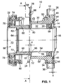
- a central release 10 for a hydraulic Clutch actuation for dry friction clutches in not Assembled state shown in basic position.
- the central releaser 10 has and has a housing 12 made of plastic one provided with an annular radial flange 14 Sleeve 16 which is drawn from a steel sheet.
- the housing 12 and the sleeve 16 together delimit a pressure chamber 18 in which an annular piston 20 is received.
- a guided on the sleeve 16 Release bearing 22 is in a known manner by means of Ring piston 20 slidably to a clutch, not shown to move out.
- the housing 12 and the release bearing 22 are by a spring 24, in the present case a helical compression spring, stretched apart, which the housing 12 with a force applied to the flange 14.
- a seal 26 for sealing of the pressure chamber 18 is arranged between the housing 12 and the flange 14 arranged.
- a seal 26 for sealing of the pressure chamber 18 arranged between the housing 12 and the flange 14 .
- the housing 12 has a substantially hollow cylindrical wall section 30 with a central through bore 32 has constant diameter and at its right in Fig. 1 End in a substantially round mounting flange in plan view 34 passes.
- the mounting flange 34 is in accordance with Fig. 2 on the outer circumference with three symmetrically distributed mounting eyes 36 provided the attachment in the motor vehicle the central release 10 on a gear wall or a gear cover (not shown) by means of screws, for example serve (not shown), which the mounting eyes 36th reach out.
- the facing away from the wall portion 30 of the housing 12 for centered attachment of the central release 10 on the transmission wall or the gear cover formed end face 40 of the Mounting flange 34 is centered with a centering depression 42 provided, the peripheral surface 44 of the radial centering the flange 14 of the sleeve 16 on the housing 12 is used.
- the level, annular end face 46 of the centering 42 has an annular groove 48 introduced in the axial direction with a Depth x for receiving the ring-shaped, preferably elastomeric Seal 26 on. In Fig. 1, the seal 26 is for clarification their actual dimensions are shown in the undeformed state.
- the seal 26 in the undeformed Condition is thicker than that by a predetermined amount Depth x of the annular groove 48 so that the seal 26 in the assembled State of the central release 10, in which the flange 14 of the Sleeve 16 as a result of its not shown abutment on the transmission wall or the gear cover flat on the end face 46 of the centering 42 of the housing 12 is pressed into the Ring groove 48 is pressed and reliably seals the pressure chamber 18. From the above description it is clear that the Sleeve 16 with its flange 14 in or on the centering 42 of the housing 12 is centered; a firm connection between sleeve 16 and housing 12 is not available.
- a substantially annular abutment 50 is designed for the spring 24, while the wall section 30 of the housing 12 on the end face, i.e. in Fig. 1 on the left side with a flat circular ring surface 52 completes that a stop surface for the cross slide 28 trains.
- an elongated, hollow cylindrical sleeve portion 54 which is coaxial to the through hole 32 of the housing 12 over the entire length the through hole 32 and beyond.
- the clutch or Gear shaft (not shown) through the sleeve section 54 passed through.
- the outer peripheral surface 56 of the sleeve portion 54 forms both a running or guide surface for the metallic ring piston 20, on the pressure chamber side shown in Fig.
- the sliding sleeve 60 separated from the annular piston 20 has a stepped one Through hole 66 with a smaller diameter section 68, on which the sliding sleeve 60 on the outer peripheral surface 56 of the sleeve section 54 is slidably guided, such that that the sliding sleeve 60 in the axial annular gap between the Through hole 32 of the housing 12 and the outer peripheral surface 56 of the sleeve 16 can be immersed in order to face the ring piston 20 to come into action.
- the tiered Through hole 66 at the free end of the sliding sleeve 60 a section 70 of larger diameter, that with the smaller diameter Section 68 forms a paragraph 72, which as Stop surface is used with which the sliding sleeve 60 on the Collar 62 of the sleeve portion 54 fastened positively and non-positively Sheet metal ring 64 can strike, which over the outer peripheral surface 56 of the sleeve portion 54 radially outward protrudes to the larger section 70 of the stepped Through hole 66 but still a slight radial play Has.
- the sheet metal ring 64 once assembled, holds the Sliding sleeve 60 on the sleeve 16 or prevents the sliding sleeve 60 can be removed from the sleeve 16.
- FIG. 2 shows the rounded on all sides at its edges Cross slide 28 on a handle portion 84, of which two Extend leg 86, seen in plan view in essentially form the shape of a C. The direction the leg 86 slightly tapering in plan view Handle part 84 is for better handling of the cross slide 28 provided with a profile 88 on both sides, as in Fig. 1 is shown.
- the one about their length is essentially leg 86 of constant width of cross slide 28 are resilient to the outside and form a part-cylindrical Inner peripheral surface 90, the diameter d im substantially the diameter of the outer peripheral surface 56 of the Corresponds to sleeve section 54.
- leg ends 92 slightly smaller than the diameter d of the partially cylindrical inner circumferential surface 90, so that the cross slide 28 in the assembled state, the sleeve section 54 Grips behind sleeve 16 in the manner of a snap connection, such as can be clearly seen in FIG. 2.
- the leg ends 92 are facing each other
- Each side is provided with a bevel 94.
- the cross slide 28 is used for mounting on the central release device 10 between the turns of the spring 24 into the annular gap 82 pushed between the housing 12 and sliding sleeve 60 until the Joining bevels 94 on the leg ends 92 of the cross slide 28 the outer peripheral surface 56 of the sleeve portion 54 to abut reach.
- the Cross slide 28 When pushing the cross slide 28 in The direction of the longitudinal axis of the central release 10 are the Leg 86 temporarily spread and snap behind the Outer circumferential surface 56 of sleeve section 54 again together, so that the cross slide 28 in the radial direction under contact of the partially cylindrical inner peripheral surface 90 on the outer peripheral surface 56 of the sleeve section 54 is positive and non-positive is fixed.
- the cross slide 28 now prevents the housing 12 against the force of the spring 24 over a predetermined amount can also remove from the flange 14 of the sleeve 16.
- the housing 12 comes with the annular surface 52 of the wall section 30 on the cross slide 28 System, which in turn faces over the cross slide 28, flat circular surface 96 of the sliding sleeve 60 and the Heel 72 of the sliding sleeve 60 on the collar 62 of the sleeve section 54 of the sleeve 16 fastened sheet metal ring 64 supports.
- the predetermined amount around the in the unassembled state of the central release 10th the housing 12 can move away from the flange 14 of the sleeve 16 until it prevented further movement by the cross slide 28 becomes constructive without problems the respective requirements can be set accordingly, namely by appropriate Choice of the thickness of the cross slide 28 and / or by appropriate adjustment of the width y of the annular gap 82, which is easily by appropriate choice of the axial length of the housing 12, the sleeve 16 and / or the sliding sleeve 60 can be realized.
- the predetermined amount by which is in the unmounted State of the central release 10, the housing 12 from the flange 14 of the sleeve 16 can move away preferably smaller or be chosen equal to the depth x of the annular groove 48 so that the Do not slide seal 26 out of annular groove 48 on housing 12 can.
- this predetermined amount can also be approximate Be zero so that when the cross slide 28 is attached essentially no relative movement between the housing 12 and Sleeve 16 is more possible.
- the cross slide 28 in the annular gap 82 between the housing 12 and the sliding sleeve 60 fixed to the sleeve 16 positively and non-positively becomes.
- the cross slide 28 in a groove provided on the outer periphery of the sliding sleeve 60 (not shown) or on one on the outer circumference of the sliding sleeve 60 attached paragraph (not shown) on the sliding sleeve 60 positively and non-positively stipulates what happens at offer a constructive design of the central release 10 would, in which the sliding sleeve 60 also in the basic position the central release 10 in the through hole 32nd of the housing 12 dips.
- the cross slide 28 in one on the outer circumference of the housing 12 groove (not shown) or on a shoulder attached to the outer periphery of the housing 12 (not shown) on the housing 12 positive and non-positive is set and thereby forms a stop surface for one attached to the sliding sleeve 60
Abstract
Description
- Fig. 1
- eine Längsschnittansicht durch einen erfindungsgemäß ausgebildeten Zentralausrücker mit montiertem Sicherungselement,
- Fig. 2
- eine Schnittansicht des in Fig. 1 dargestellten Zentralausrückers entsprechend dem Schnittverlauf A-A in Fig. 1,
- Fig. 3
- eine perspektivische Darstellung des in Fig. 1 gezeigten Zentralausrückers mit montiertem Sicherungselement und
- Fig. 4
- eine perspektivische Darstellung des in Fig. 1 gezeigten Zentralausrückers mit abgenommenem Sicherungselement.
- 10
- Zentralausrücker
- 12
- Gehäuse
- 14
- Flansch
- 16
- Hülse
- 18
- Druckraum
- 20
- Ringkolben
- 22
- Ausrücklager
- 24
- Feder
- 26
- Dichtung
- 28
- Querschieber
- 30
- Wandungsabschnitt
- 32
- Durchgangsbohrung
- 34
- Befestigungsflansch
- 36
- Befestigungsauge
- 38
- Hydraulikanschluß
- 40
- Stirnfläche
- 42
- Zentriersenkung
- 44
- Umfangsfläche
- 46
- Stirnfläche
- 48
- Ringnut
- 50
- Widerlager
- 52
- Kreisringfläche
- 54
- Hülsenabschnitt
- 56
- Außenumfangsfläche
- 58
- Dichtelement
- 60
- Schiebehülse
- 62
- Kragen
- 64
- Blechring
- 66
- gestufte Durchgangsbohrung
- 68
- durchmesserkleinerer Abschnitt
- 70
- durchmessergrößerer Abschnitt
- 72
- Absatz
- 74
- Innenring
- 76
- Bund
- 78
- Sicherungsring
- 80
- Widerlager
- 82
- Ringspalt
- 84
- Griffteil
- 86
- Schenkel
- 88
- Profil
- 90
- teilzylindrische Innenumfangsfläche
- 92
- Schenkelende
- 94
- Fügeschräge
- 96
- Kreisringfläche
- a
- lichter Abstand der Schenkelenden 92
- d
- Durchmesser der Innenumfangsfläche 90
- x
- Tiefe der Ringnut 48
- y
- Breite des Ringspalts 82
Claims (11)
- Zentralausrücker (10) für eine hydraulische Kupplungsbetätigung, mit einem Gehäuse (12) und einer mit einem Flansch (14) versehenen Hülse (16), die zusammen einen Druckraum (18) zur Aufnahme eines Ringkolbens (20) begrenzen, mittels dessen ein auf der Hülse (16) geführtes Ausrücklager (22) verschiebbar ist, wobei eine das Gehäuse (12) und das Ausrücklager (22) auseinander spannende Feder (24) das Gehäuse (12) mit einer auf den Flansch (14) gerichteten Kraft beaufschlagt und zwischen dem Gehäuse (12) und dem Flansch (14) eine Dichtung (26) zur Abdichtung des Druckraums (18) angeordnet ist, gekennzeichnet durch ein für den Betrieb des Zentralausrückers (10) abnehmbares Sicherungselement (28), das im unmontierten Zustand des Zentralausrückers (10) einen Anschlag für das Gehäuse (12) ausbildet und das Gehäuse (12) alleine daran hindert, sich entgegen der Kraft der Feder (24) über einen vorbestimmten Betrag hinaus vom Flansch (14) der Hülse (16) wegzubewegen.
- Zentralausrücker (10) nach Anspruch 1, dadurch gekennzeichnet, daß das Gehäuse (12) an seiner dem Flansch (14) der Hülse (16) zugewandten Stirnfläche (46) oder der Flansch (14) der Hülse (16) an seiner dem Gehäuse (12) zugewandten Stirnfläche mit einer Ringnut (48) versehen ist, in der die Dichtung (26) aufgenommen ist, deren Dicke im unverformten Zustand größer ist als die Tiefe (x) der Ringnut (48), wobei der vorbestimmte Betrag, um den sich im unmontierten Zustand des Zentralausrückers (10) das Gehäuse (12) vom Flansch (14) der Hülse (16) wegbewegen kann, kleiner oder gleich der Tiefe (x) der Ringnut (48) ist.
- Zentralausrücker (10) nach Anspruch 1 oder 2, dadurch gekennzeichnet, daß das Ausrücklager (22) auf der Hülse (16) durch eine mittels eines Anschlags (64) an der Hülse (16) gehaltene Schiebehülse (60) geführt ist, wobei das Sicherungselement als Querschieber (28) ausgebildet ist, der in einem Ringspalt (82) zwischen der Schiebehülse (60) und dem Gehäuse (12) an der Hülse (16) form- und kraftschlüssig festlegbar ist.
- Zentralausrücker (10) nach Anspruch 1 oder 2, dadurch gekennzeichnet, daß das Ausrücklager (22) auf der Hülse (16) durch eine mittels eines Anschlags (64) an der Hülse (16) gehaltene Schiebehülse (60) geführt ist, wobei das Sicherungselement als Querschieber (28) ausgebildet ist, der in einer am Außenumfang der Schiebehülse (60) angebrachten Nut oder an einem am Außenumfang der Schiebehülse (60) angebrachten Absatz an der Schiebehülse (60) form- und kraftschlüssig festlegbar ist.
- Zentralausrücker (10) nach Anspruch 1 oder 2, dadurch gekennzeichnet, daß das Ausrücklager (22) auf der Hülse (16) durch eine mittels eines Anschlags (64) an der Hülse (16) gehaltene Schiebehülse (60) geführt ist, wobei das Sicherungselement als Querschieber (28) ausgebildet ist, der in einer am Außenumfang des Gehäuses (12) angebrachten Nut oder an einem am Außenumfang des Gehäuses (12) angebrachten Absatz am Gehäuse (12) form- und kraftschlüssig festlegbar ist und der eine Anschlagfläche für eine an der Schiebehülse (60) befestigte, das Gehäuse (12) teleskopisch umgebende Schutzhülse oder für ein an der Schiebehülse (60) befestigtes Widerlager (80) für die Feder (24) aufweist.
- Zentralausrücker (10) nach einem der Ansprüche 3 bis 5, dadurch gekennzeichnet, daß der Querschieber (28) einen Griffteil (84) aufweist, von dem sich zwei Schenkel (86) wegerstrecken, die in der Draufsicht (Fig. 2) gesehen im wesentlichen die Form eines C's bilden.
- Zentralausrücker (10) nach Anspruch 6, dadurch gekennzeichnet, daß die Griffflächen des Griffteil (84) jeweils mit einem Profil (88) versehen sind.
- Zentralausrücker (10) nach Anspruch 6 oder 7, dadurch gekennzeichnet, daß die Schenkel (86) elastisch auffederbar sind und eine teilzylindrische Innenumfangsfläche (90) aufweisen, wobei der lichte Abstand (a) der Schenkelenden (92) geringfügig kleiner ist als der Durchmesser (d) der teilzylindrischen Innenumfangsfläche (90), so daß der Querschieber (28) im montierten Zustand die Hülse (16), die Schiebehülse (60) bzw. das Gehäuse (12) in der Art einer Schnappverbindung hintergreift.
- Zentralausrücker (10) nach einem der Ansprüche 6 bis 8, dadurch gekennzeichnet, daß die Schenkelenden (92) auf den einander zugewandten Seiten mit jeweils einer Fügeschräge (94) versehen sind.
- Zentralausrücker (10) nach einem der vorhergehenden Ansprüche, dadurch gekennzeichnet, daß das Sicherungselement bzw. der Querschieber (28) aus Kunststoff besteht.
- Zentralausrücker (10) nach einem der vorhergehenden Ansprüche, dadurch gekennzeichnet, daß das Gehäuse (12) aus Kunststoff und die Hülse (16) aus Stahl besteht.
Applications Claiming Priority (2)
| Application Number | Priority Date | Filing Date | Title |
|---|---|---|---|
| DE19944083 | 1999-09-15 | ||
| DE19944083A DE19944083A1 (de) | 1999-09-15 | 1999-09-15 | Zentralausrücker für eine hydraulische Kupplungsbetätigung |
Publications (2)
| Publication Number | Publication Date |
|---|---|
| EP1085228A1 true EP1085228A1 (de) | 2001-03-21 |
| EP1085228B1 EP1085228B1 (de) | 2004-05-06 |
Family
ID=7922025
Family Applications (1)
| Application Number | Title | Priority Date | Filing Date |
|---|---|---|---|
| EP00118710A Expired - Lifetime EP1085228B1 (de) | 1999-09-15 | 2000-08-30 | Zentralausrücker für eine hydraulische Kupplungsbetätigung |
Country Status (4)
| Country | Link |
|---|---|
| US (1) | US6390267B1 (de) |
| EP (1) | EP1085228B1 (de) |
| AT (1) | ATE266160T1 (de) |
| DE (2) | DE19944083A1 (de) |
Cited By (1)
| Publication number | Priority date | Publication date | Assignee | Title |
|---|---|---|---|---|
| WO2008086763A1 (de) * | 2007-01-15 | 2008-07-24 | Luk Lamellen Und Kupplungsbau Beteiligungs Kg | Nehmerzylinder |
Families Citing this family (8)
| Publication number | Priority date | Publication date | Assignee | Title |
|---|---|---|---|---|
| DE10314864B3 (de) * | 2003-04-02 | 2004-10-28 | Fte Automotive Gmbh & Co. Kg | Zentralausrücker für eine hydraulische Kupplungsbetätigung |
| DE102010021788A1 (de) | 2010-05-27 | 2011-12-01 | Schaeffler Technologies Gmbh & Co. Kg | Ausrücklageranordnung |
| CN102777509A (zh) * | 2011-05-13 | 2012-11-14 | 谢夫勒科技股份两合公司 | 改进的液压从动缸 |
| DE102012212539A1 (de) | 2012-07-18 | 2014-01-23 | Schaeffler Technologies AG & Co. KG | Ausrücklageranordnung |
| DE102014001073A1 (de) | 2014-01-30 | 2015-07-30 | Fte Automotive Gmbh | Vorrichtung zur hydraulischen Betätigung einer Kraftfahrzeug-Reibkupplung |
| DE102014212678B4 (de) * | 2014-07-01 | 2023-05-25 | Schaeffler Technologies AG & Co. KG | Transportsicherung für einen konzentrischen Nehmerzylinder |
| WO2016169558A1 (de) * | 2015-04-20 | 2016-10-27 | Schaeffler Technologies AG & Co. KG | Betätigungslager |
| DE102018220400A1 (de) * | 2018-11-28 | 2020-05-28 | Zf Friedrichshafen Ag | Anordnung zur Betätigung einer Kupplung |
Citations (10)
| Publication number | Priority date | Publication date | Assignee | Title |
|---|---|---|---|---|
| US4344516A (en) * | 1979-04-20 | 1982-08-17 | Fichtel & Sachs Ag | Disengaging device |
| EP0095841B1 (de) | 1982-05-28 | 1986-08-06 | Automotive Products Public Limited Company | Kupplungsbetätigungsanordnung für Kraftwagengetriebe |
| EP0168932B1 (de) | 1984-06-13 | 1989-03-08 | LUCAS INDUSTRIES public limited company | Hydraulischer Nehmerzylinder |
| DE4109125A1 (de) | 1991-03-20 | 1992-09-24 | Fichtel & Sachs Ag | Vakuumunterstuetztes befuellen einer hydraulischen kupplungsbetaetigung |
| US5183141A (en) * | 1990-05-24 | 1993-02-02 | Kabushiki Kaisha Daikin Seisakusho | Release mechanism for pull-type clutch |
| DE4313346A1 (de) | 1993-04-23 | 1994-10-27 | Fichtel & Sachs Ag | Hydraulisch betätigbares Ausrücksystem |
| US5655639A (en) * | 1993-09-29 | 1997-08-12 | Valeo | Motor vehicle hydraulic clutch assembly of the pull to release type |
| FR2745616A1 (fr) * | 1996-02-29 | 1997-09-05 | Valeo | Dispositif de maintien, notamment pour vehicule automobile |
| US5810145A (en) * | 1995-09-14 | 1998-09-22 | Valeo | Hydraulically controlled disengagement device for a clutch, notably for motor vehicles |
| DE19742468A1 (de) | 1997-09-26 | 1999-04-01 | Schaeffler Waelzlager Ohg | Nehmerzylindergehäuse aus Kunststoff, in das eine Führungshülse aus Stahl eingesetzt ist |
Family Cites Families (8)
| Publication number | Priority date | Publication date | Assignee | Title |
|---|---|---|---|---|
| DE3119367C1 (de) * | 1981-05-15 | 1982-12-09 | Bayerische Motoren Werke AG, 8000 München | Vorrichtung zum hydraulischen Betaetigen einer gezogenen Reibungskupplung fuer Kraftfahrzeuge |
| GB2112490B (en) * | 1981-12-15 | 1985-07-03 | Automotive Products Plc | Hydraulic slave cylinder for a clutch release bearing |
| US4687084A (en) * | 1985-07-22 | 1987-08-18 | Automotive Products Plc | Clutch release apparatus for pull type clutches |
| DE4130525C2 (de) | 1991-09-13 | 2000-05-18 | Mannesmann Sachs Ag | Fluidbetätigbares Ausrücksystem |
| DE19622773C1 (de) * | 1996-06-07 | 1997-05-07 | Fichtel & Sachs Ag | Nehmerzylinder zur Betätigung einer Reibkupplung |
| DE19637903A1 (de) * | 1996-09-18 | 1998-03-19 | Mannesmann Sachs Ag | Vorrichtung zur Verschleißanzeige einer Reibungskupplung |
| DE19754176B4 (de) * | 1997-12-06 | 2006-07-06 | Luk Lamellen Und Kupplungsbau Beteiligungs Kg | Führungsflächen in einem Nehmerzylinder, die durch Kugelstrahlen behandelt sind |
| DE19811657A1 (de) * | 1998-03-18 | 1999-09-23 | Schaeffler Waelzlager Ohg | Hydraulisch betätigbares Ausrücksystem |
-
1999
- 1999-09-15 DE DE19944083A patent/DE19944083A1/de not_active Withdrawn
-
2000
- 2000-08-30 AT AT00118710T patent/ATE266160T1/de not_active IP Right Cessation
- 2000-08-30 EP EP00118710A patent/EP1085228B1/de not_active Expired - Lifetime
- 2000-08-30 DE DE50006311T patent/DE50006311D1/de not_active Expired - Lifetime
- 2000-09-13 US US09/661,172 patent/US6390267B1/en not_active Expired - Lifetime
Patent Citations (10)
| Publication number | Priority date | Publication date | Assignee | Title |
|---|---|---|---|---|
| US4344516A (en) * | 1979-04-20 | 1982-08-17 | Fichtel & Sachs Ag | Disengaging device |
| EP0095841B1 (de) | 1982-05-28 | 1986-08-06 | Automotive Products Public Limited Company | Kupplungsbetätigungsanordnung für Kraftwagengetriebe |
| EP0168932B1 (de) | 1984-06-13 | 1989-03-08 | LUCAS INDUSTRIES public limited company | Hydraulischer Nehmerzylinder |
| US5183141A (en) * | 1990-05-24 | 1993-02-02 | Kabushiki Kaisha Daikin Seisakusho | Release mechanism for pull-type clutch |
| DE4109125A1 (de) | 1991-03-20 | 1992-09-24 | Fichtel & Sachs Ag | Vakuumunterstuetztes befuellen einer hydraulischen kupplungsbetaetigung |
| DE4313346A1 (de) | 1993-04-23 | 1994-10-27 | Fichtel & Sachs Ag | Hydraulisch betätigbares Ausrücksystem |
| US5655639A (en) * | 1993-09-29 | 1997-08-12 | Valeo | Motor vehicle hydraulic clutch assembly of the pull to release type |
| US5810145A (en) * | 1995-09-14 | 1998-09-22 | Valeo | Hydraulically controlled disengagement device for a clutch, notably for motor vehicles |
| FR2745616A1 (fr) * | 1996-02-29 | 1997-09-05 | Valeo | Dispositif de maintien, notamment pour vehicule automobile |
| DE19742468A1 (de) | 1997-09-26 | 1999-04-01 | Schaeffler Waelzlager Ohg | Nehmerzylindergehäuse aus Kunststoff, in das eine Führungshülse aus Stahl eingesetzt ist |
Cited By (1)
| Publication number | Priority date | Publication date | Assignee | Title |
|---|---|---|---|---|
| WO2008086763A1 (de) * | 2007-01-15 | 2008-07-24 | Luk Lamellen Und Kupplungsbau Beteiligungs Kg | Nehmerzylinder |
Also Published As
| Publication number | Publication date |
|---|---|
| DE50006311D1 (de) | 2004-06-09 |
| DE19944083A1 (de) | 2001-04-12 |
| EP1085228B1 (de) | 2004-05-06 |
| US6390267B1 (en) | 2002-05-21 |
| ATE266160T1 (de) | 2004-05-15 |
Similar Documents
| Publication | Publication Date | Title |
|---|---|---|
| EP1512882B1 (de) | Hydraulikzylinder | |
| DE102017001410A1 (de) | Selbstjustierender pneumatischer Kupplungsaktor | |
| DE4339652A1 (de) | Hydraulisch betätigbare Ausrücker-Nehmerzylinder für eine Kraftfahrzeug-Reibungskupplung | |
| WO2012155884A1 (de) | Hydraulisch betätigter kupplungsausrücker mit mehrteiligem gehäuse | |
| EP3478969A1 (de) | Geberzylinder, insbesondere für eine hydraulische kupplungsbetätigungsvorrichtung in kraftfahrzeugen | |
| DE19680491C5 (de) | Abdichtungen in einem Geberzylinder | |
| DE19716473A1 (de) | Zentralausrücker für eine hydraulische Kupplungsbetätigung | |
| EP1085228B1 (de) | Zentralausrücker für eine hydraulische Kupplungsbetätigung | |
| DE19524312B4 (de) | Kolben für einen Nehmerzylinder einer hydraulisch betätigbaren Reibungskupplung | |
| DE102008058704A1 (de) | Hydraulikzylinder | |
| EP1666753B1 (de) | Hydraulikzylinder, insbesondere Nehmerzylinder für eine hydraulische Kupplungsbetätigung für Kraftfahrzeuge | |
| DE102010054259B4 (de) | Geberzylindereinrichtung | |
| EP3477157B1 (de) | Differentialsperre | |
| DE102017201411B4 (de) | Schaltmodul für eine Differentialsperre, für ein Schaltgetriebe oder für eine Achszuschaltung | |
| DE102009016284A1 (de) | Befestigungsanordnung | |
| DE19809852C2 (de) | Anschlußvorrichtung für Sanitär-Rohrleitungen | |
| DE19636399A1 (de) | Druckzylinder mit einer verschiebbaren Zwischenkammer | |
| EP3073127A1 (de) | Kolben-hülsen-bauteil für ein mit druckmittel beaufschlagbares stellglied, mit druckmittel beaufschlagbares stellglied sowie verteilergetriebe | |
| WO1996023684A1 (de) | Hydraulisches aggregat | |
| DE1530207C3 (de) | Hydraulisch gedämpfte Stoßaufnahmevorrichtung für Eisenbahnwagen | |
| DE10107877A1 (de) | Hydraulische Ausrückvorrichtung für eine Kupplung | |
| DE3429492A1 (de) | Doppeltwirkender arbeitszylinder | |
| DE4401030A1 (de) | Ausdrückvorrichtung mit hydraulischem Betätigungsorgan, insbesondere für eine zugkraftbetätigte Kupplung | |
| DE102005060869A1 (de) | Betätigungsanordnung | |
| DE3530565A1 (de) | Lagerung des kupplungskoerpers einer anhaengerkupplung in der traverse |
Legal Events
| Date | Code | Title | Description |
|---|---|---|---|
| PUAI | Public reference made under article 153(3) epc to a published international application that has entered the european phase |
Free format text: ORIGINAL CODE: 0009012 |
|
| 17P | Request for examination filed |
Effective date: 20010120 |
|
| AK | Designated contracting states |
Kind code of ref document: A1 Designated state(s): AT BE CH CY DE DK ES FI FR GB GR IE IT LI LU MC NL PT SE |
|
| AX | Request for extension of the european patent |
Free format text: AL;LT;LV;MK;RO;SI |
|
| AKX | Designation fees paid |
Free format text: AT BE CH CY DE DK ES FI FR GB GR IE IT LI LU MC NL PT SE |
|
| GRAP | Despatch of communication of intention to grant a patent |
Free format text: ORIGINAL CODE: EPIDOSNIGR1 |
|
| GRAS | Grant fee paid |
Free format text: ORIGINAL CODE: EPIDOSNIGR3 |
|
| RAP1 | Party data changed (applicant data changed or rights of an application transferred) |
Owner name: FTEAUTOMOTIVE GMBH & CO. KG |
|
| GRAA | (expected) grant |
Free format text: ORIGINAL CODE: 0009210 |
|
| AK | Designated contracting states |
Kind code of ref document: B1 Designated state(s): AT BE CH CY DE DK ES FI FR GB GR IE IT LI LU MC NL PT SE |
|
| PG25 | Lapsed in a contracting state [announced via postgrant information from national office to epo] |
Ref country code: CY Free format text: LAPSE BECAUSE OF FAILURE TO SUBMIT A TRANSLATION OF THE DESCRIPTION OR TO PAY THE FEE WITHIN THE PRESCRIBED TIME-LIMIT Effective date: 20040506 Ref country code: NL Free format text: LAPSE BECAUSE OF FAILURE TO SUBMIT A TRANSLATION OF THE DESCRIPTION OR TO PAY THE FEE WITHIN THE PRESCRIBED TIME-LIMIT Effective date: 20040506 Ref country code: IE Free format text: LAPSE BECAUSE OF FAILURE TO SUBMIT A TRANSLATION OF THE DESCRIPTION OR TO PAY THE FEE WITHIN THE PRESCRIBED TIME-LIMIT Effective date: 20040506 Ref country code: FI Free format text: LAPSE BECAUSE OF FAILURE TO SUBMIT A TRANSLATION OF THE DESCRIPTION OR TO PAY THE FEE WITHIN THE PRESCRIBED TIME-LIMIT Effective date: 20040506 |
|
| REG | Reference to a national code |
Ref country code: GB Ref legal event code: FG4D Free format text: NOT ENGLISH |
|
| REG | Reference to a national code |
Ref country code: CH Ref legal event code: EP |
|
| REF | Corresponds to: |
Ref document number: 50006311 Country of ref document: DE Date of ref document: 20040609 Kind code of ref document: P |
|
| REG | Reference to a national code |
Ref country code: IE Ref legal event code: FG4D Free format text: GERMAN |
|
| PG25 | Lapsed in a contracting state [announced via postgrant information from national office to epo] |
Ref country code: SE Free format text: LAPSE BECAUSE OF FAILURE TO SUBMIT A TRANSLATION OF THE DESCRIPTION OR TO PAY THE FEE WITHIN THE PRESCRIBED TIME-LIMIT Effective date: 20040806 Ref country code: DK Free format text: LAPSE BECAUSE OF FAILURE TO SUBMIT A TRANSLATION OF THE DESCRIPTION OR TO PAY THE FEE WITHIN THE PRESCRIBED TIME-LIMIT Effective date: 20040806 Ref country code: GR Free format text: LAPSE BECAUSE OF FAILURE TO SUBMIT A TRANSLATION OF THE DESCRIPTION OR TO PAY THE FEE WITHIN THE PRESCRIBED TIME-LIMIT Effective date: 20040806 |
|
| PG25 | Lapsed in a contracting state [announced via postgrant information from national office to epo] |
Ref country code: ES Free format text: LAPSE BECAUSE OF FAILURE TO SUBMIT A TRANSLATION OF THE DESCRIPTION OR TO PAY THE FEE WITHIN THE PRESCRIBED TIME-LIMIT Effective date: 20040817 |
|
| PG25 | Lapsed in a contracting state [announced via postgrant information from national office to epo] |
Ref country code: LU Free format text: LAPSE BECAUSE OF NON-PAYMENT OF DUE FEES Effective date: 20040830 Ref country code: AT Free format text: LAPSE BECAUSE OF NON-PAYMENT OF DUE FEES Effective date: 20040830 |
|
| PG25 | Lapsed in a contracting state [announced via postgrant information from national office to epo] |
Ref country code: BE Free format text: LAPSE BECAUSE OF NON-PAYMENT OF DUE FEES Effective date: 20040831 Ref country code: CH Free format text: LAPSE BECAUSE OF NON-PAYMENT OF DUE FEES Effective date: 20040831 Ref country code: MC Free format text: LAPSE BECAUSE OF NON-PAYMENT OF DUE FEES Effective date: 20040831 Ref country code: LI Free format text: LAPSE BECAUSE OF NON-PAYMENT OF DUE FEES Effective date: 20040831 |
|
| GBT | Gb: translation of ep patent filed (gb section 77(6)(a)/1977) |
Effective date: 20040812 |
|
| NLV1 | Nl: lapsed or annulled due to failure to fulfill the requirements of art. 29p and 29m of the patents act | ||
| REG | Reference to a national code |
Ref country code: IE Ref legal event code: FD4D |
|
| ET | Fr: translation filed | ||
| BERE | Be: lapsed |
Owner name: FTE AUTOMOTIVE G.M.B.H. & CO. KG Effective date: 20040831 |
|
| PLBE | No opposition filed within time limit |
Free format text: ORIGINAL CODE: 0009261 |
|
| STAA | Information on the status of an ep patent application or granted ep patent |
Free format text: STATUS: NO OPPOSITION FILED WITHIN TIME LIMIT |
|
| REG | Reference to a national code |
Ref country code: CH Ref legal event code: PL |
|
| 26N | No opposition filed |
Effective date: 20050208 |
|
| REG | Reference to a national code |
Ref country code: GB Ref legal event code: 732E |
|
| REG | Reference to a national code |
Ref country code: FR Ref legal event code: TP Ref country code: FR Ref legal event code: CD |
|
| BERE | Be: lapsed |
Owner name: *FTE AUTOMOTIVE G.M.B.H. & CO. K.G. Effective date: 20040831 |
|
| PG25 | Lapsed in a contracting state [announced via postgrant information from national office to epo] |
Ref country code: PT Free format text: LAPSE BECAUSE OF NON-PAYMENT OF DUE FEES Effective date: 20041006 |
|
| REG | Reference to a national code |
Ref country code: FR Ref legal event code: PLFP Year of fee payment: 17 |
|
| REG | Reference to a national code |
Ref country code: FR Ref legal event code: PLFP Year of fee payment: 18 |
|
| PGFP | Annual fee paid to national office [announced via postgrant information from national office to epo] |
Ref country code: IT Payment date: 20170726 Year of fee payment: 18 |
|
| REG | Reference to a national code |
Ref country code: FR Ref legal event code: PLFP Year of fee payment: 19 |
|
| PG25 | Lapsed in a contracting state [announced via postgrant information from national office to epo] |
Ref country code: IT Free format text: LAPSE BECAUSE OF NON-PAYMENT OF DUE FEES Effective date: 20180830 |
|
| PGFP | Annual fee paid to national office [announced via postgrant information from national office to epo] |
Ref country code: DE Payment date: 20190807 Year of fee payment: 20 Ref country code: FR Payment date: 20190830 Year of fee payment: 20 |
|
| PGFP | Annual fee paid to national office [announced via postgrant information from national office to epo] |
Ref country code: GB Payment date: 20190821 Year of fee payment: 20 |
|
| REG | Reference to a national code |
Ref country code: DE Ref legal event code: R071 Ref document number: 50006311 Country of ref document: DE |
|
| REG | Reference to a national code |
Ref country code: GB Ref legal event code: PE20 Expiry date: 20200829 |
|
| PG25 | Lapsed in a contracting state [announced via postgrant information from national office to epo] |
Ref country code: GB Free format text: LAPSE BECAUSE OF EXPIRATION OF PROTECTION Effective date: 20200829 |