EP1085228A1 - Release device for hydraulic clutch actuator - Google Patents
Release device for hydraulic clutch actuator Download PDFInfo
- Publication number
- EP1085228A1 EP1085228A1 EP00118710A EP00118710A EP1085228A1 EP 1085228 A1 EP1085228 A1 EP 1085228A1 EP 00118710 A EP00118710 A EP 00118710A EP 00118710 A EP00118710 A EP 00118710A EP 1085228 A1 EP1085228 A1 EP 1085228A1
- Authority
- EP
- European Patent Office
- Prior art keywords
- sleeve
- housing
- flange
- central release
- sliding sleeve
- Prior art date
- Legal status (The legal status is an assumption and is not a legal conclusion. Google has not performed a legal analysis and makes no representation as to the accuracy of the status listed.)
- Granted
Links
Images


Classifications
-
- F—MECHANICAL ENGINEERING; LIGHTING; HEATING; WEAPONS; BLASTING
- F16—ENGINEERING ELEMENTS AND UNITS; GENERAL MEASURES FOR PRODUCING AND MAINTAINING EFFECTIVE FUNCTIONING OF MACHINES OR INSTALLATIONS; THERMAL INSULATION IN GENERAL
- F16D—COUPLINGS FOR TRANSMITTING ROTATION; CLUTCHES; BRAKES
- F16D25/00—Fluid-actuated clutches
- F16D25/08—Fluid-actuated clutches with fluid-actuated member not rotating with a clutching member
- F16D25/082—Fluid-actuated clutches with fluid-actuated member not rotating with a clutching member the line of action of the fluid-actuated members co-inciding with the axis of rotation
- F16D25/083—Actuators therefor
Abstract
Description
Die vorliegende Erfindung bezieht sich auf einen Zentralausrücker für eine hydraulische Kupplungsbetätigung gemäß dem Oberbegriff des Patentanspruchs 1. Insbesondere bezieht sich die Erfindung auf einen Zentralausrücker einer hydraulischen Kupplungsbetätigung für eine Kraftfahrzeug-Kupplung.The present invention relates to a central slave cylinder for hydraulic clutch actuation according to the preamble of claim 1. In particular, the invention relates to a central release of a hydraulic clutch actuation for a motor vehicle clutch.
Eine herkömmliche hydraulische Kupplungsbetätigung für Kraftfahrzeuge hat einen an einen mit Hydraulikflüssigkeit gefüllten Ausgleichsbehälter angeschlossenen Geberzylinder, der über ein Kupplungspedal betätigt werden kann. Der Geberzylinder ist über eine Druckleitung mit einem Nehmerzylinder hydraulisch verbunden, so daß der durch Niedertreten des Kupplungspedals im Geberzylinder erzeugte Druck über die Flüssigkeitssäule in der Druckleitung auf den Nehmerzylinder übertragbar ist. Im Ergebnis wird das Ausrücklager der Kupplung von dem Nehmerzylinder mit einer Betätigungskraft beaufschlagt, um über einen Ausrückmechanismus die Kupplungsdruckplatte von der Kupplungsmitnehmerscheibe und somit den Motor vom Getriebe des Kraftfahrzeugs zu trennen.A conventional hydraulic clutch control for motor vehicles has one on one filled with hydraulic fluid Expansion tank connected master cylinder, which via a Clutch pedal can be operated. The master cylinder is over a pressure line hydraulically connected to a slave cylinder, so that by depressing the clutch pedal in the master cylinder generated pressure across the liquid column in the Pressure line is transferable to the slave cylinder. As a result becomes the clutch release bearing from the slave cylinder acted upon by an actuating force via a release mechanism the clutch pressure plate from the clutch drive plate and thus the engine from the gearbox of the motor vehicle to separate.
Um eine gleichmäßige Betätigung der Kupplung bei geringem Platzbedarf des Nehmerzylinders zu gewährleisten, ist im Stand der Technik vorgeschlagen worden, den Nehmerzylinder als Ringzylinder auszubilden, der um die Kupplungs- bzw. Getriebewelle herum angeordnet und am Getriebe befestigt ist. In dem Ringzylinder ist ein Ringkolben in axialer Richtung der Kupplungs- bzw. Getriebewelle gleitend angeordnet, der mit dem Ausrücklager der Kupplung in Wirkverbindung steht. Bei hydraulischer Beaufschlagung des Ringzylinders über die Druckleitung wirkt der Ringkolben über das Ausrücklager auf den Ausrückhebel der Kupplung, um diese auszurücken. Derartige Nehmerzylinder werden aufgrund ihrer zur Kupplungs- bzw. Getriebewelle konzentrischen Anordnung auch als Zentralausrücker bezeichnet.To ensure even actuation of the clutch with little Ensuring that the slave cylinder takes up space is at a standstill the technology has been proposed, the slave cylinder as a ring cylinder train the around the clutch or transmission shaft arranged around and attached to the transmission. In the ring cylinder is an annular piston in the axial direction of the clutch or Gear shaft slidably arranged with the release bearing the coupling is in operative connection. With hydraulic loading of the ring cylinder acts on the pressure line Ring piston over the release bearing on the clutch release lever, to move them out. Such slave cylinders will be due to their concentricity to the clutch or gear shaft Arrangement also referred to as a central release.
Im Stand der Technik fehlt es nicht an Vorschlägen, wie derartige Zentralausrücker auszubilden sind (z.B. EP 0 095 841 B1, EP 0 168 932 B1, DE 41 09 125 A1, DE 43 13 346 A1, DE 197 42 468 A1). Den hier betrachteten Zentralausrückern ist gemein, daß sie ein Gehäuse mit einer durchgehenden Bohrung besitzen, das spanend aus einem metallischen Werkstoff gearbeitet bzw. aus Kunststoff formgespritzt ist und an einer Getriebewand im Kraftfahrzeug befestigt werden kann. In der Bohrung ist koaxial zum Gehäuse eine gezogene Stahlhülse vorgesehen, die endseitig einen sich in radialer Richtung erstreckenden Flansch aufweist, der im montierten Zustand des Zentralausrückers zwischen dem Gehäuse und der Getriebewand angeordnet ist. Bei diesem Stand der Technik begrenzt die Innenumfangsfläche der Bohrung zusammen mit dem radialen Flansch und der Außenumfangsfläche der Stahlhülse den Druckraum, in dem der auf der Stahlhülse geführte, mit einem Dichtelement versehene Ringkolben angeordnet ist.In the prior art there are no shortages of proposals such as such Central releasers are to be trained (e.g. EP 0 095 841 B1, EP 0 168 932 B1, DE 41 09 125 A1, DE 43 13 346 A1, DE 197 42 468 A1). The central releasers considered here have one thing in common, that they have a housing with a through hole, that machined from a metallic material or is injection molded from plastic and on a gear wall in the Motor vehicle can be attached. In the bore is coaxial a drawn steel sleeve is provided to the housing, the ends has a flange extending in the radial direction, the in the assembled state of the central release between the Housing and the gear wall is arranged. At this stand technology limits the inner circumferential surface of the bore together with the radial flange and the outer peripheral surface of the Steel sleeve the pressure chamber in which the guided on the steel sleeve arranged with a sealing element annular piston is.
Zur Abdichtung des Druckraums wird zwischen dem Gehäuse und dem Flansch der Stahlhülse in der Regel ein elastomerer Dichtring vorgesehen. Ferner ist die Stahlhülse an ihrem Flansch mit dem Gehäuse mittels einer Schraubverbindung (EP 0 095 841 B1), durch Verstemmen des Gehäuses (EP 0 168 932 B1), mittels eines Sicherungsrings (DE 41 09 125 A1), durch eine Schweißverbindung, Nietung, Durchsetzfügung oder eine Rollverbindung (DE 43 13 346 A1) bzw. mittels einer Schnappverbindung (DE 197 42 468 A1) fest verbunden, so daß der Dichtring zwischen dem Gehäuse und dem Flansch der Stahlhülse sowie das Dichtelement am Ringkolben nicht zugänglich sind und somit nicht beschädigt werden können. Ein Nachteil dieses Stands der Technik ist jedoch darin zu sehen, daß die Ausbildung der Verbindung zwischen dem Gehäuse und dem Flansch der Stahlhülse einen beträchtlichen Aufwand erfordert, der einen nicht unerheblichen Teil der Gestehungskosten dieses Massenartikels ausmacht.To seal the pressure chamber between the housing and the The flange of the steel sleeve is usually an elastomeric sealing ring intended. Furthermore, the steel sleeve is on its flange with the Housing by means of a screw connection (EP 0 095 841 B1), by caulking the housing (EP 0 168 932 B1), using a Circlip (DE 41 09 125 A1), by a welded connection, Riveting, enforcement or a rolling connection (DE 43 13 346 A1) or by means of a snap connection (DE 197 42 468 A1) firmly connected so that the sealing ring between the housing and the flange of the steel sleeve and the sealing element on the ring piston are not accessible and are therefore not damaged can. A disadvantage of this prior art, however, is that to see that the formation of the connection between the housing and the flange of the steel sleeve a considerable effort requires a not inconsiderable part of the production costs constitutes this mass article.
Gegenüber dem gattungsbildenden Stand der Technik gemäß der EP 0 168 932 B1 liegt der Erfindung daher die Aufgabe zugrunde, einen einfach ausgebildeten Zentralausrücker zu schaffen, der ohne die Gefahr von Funktionsproblemen günstiger herzustellen ist.Compared to the generic state of the art according to the EP 0 168 932 B1 the invention is therefore based on the object to create a simply trained central releaser who less expensive to manufacture without the risk of functional problems is.
Diese Aufgabe wird durch die im Patentanspruch 1 angegebenen Merkmale gelöst. Vorteilhafte bzw. zweckmäßige Weiterbildungen der Erfindung sind Gegenstand der Patentansprüche 2 bis 11.This object is achieved by the specified in claim 1 Features resolved. Advantageous or expedient further training the invention are the subject of claims 2 to 11.
Erfindungsgemäß ist bei einem Zentralausrücker für eine hydraulische Kupplungsbetätigung, der ein Gehäuse und eine mit einem Flansch versehene Hülse aufweist, die zusammen einen Druckraum zur Aufnahme eines Ringkolbens begrenzen, mittels dessen ein auf der Hülse geführtes Ausrücklager verschiebbar ist, wobei eine das Gehäuse und das Ausrücklager auseinander spannende Feder das Gehäuse mit einer auf den Flansch gerichteten Kraft beaufschlagt und zwischen dem Gehäuse und dem Flansch eine Dichtung zur Abdichtung des Druckraums angeordnet ist, ein für den Betrieb des Zentralausrückers abnehmbares Sicherungselement vorgesehen, das im unmontierten Zustand des Zentralausrückers einen Anschlag für das Gehäuse ausbildet und das Gehäuse alleine daran hindert, sich entgegen der Kraft der Feder über einen vorbestimmten Betrag hinaus vom Flansch der Hülse wegzubewegen.According to the invention in a central release for a hydraulic Clutch actuation, which is a housing and one with a Has flange provided sleeve, which together a pressure chamber limit for receiving an annular piston, by means of which a on the sleeve guided release bearing is displaceable, wherein a spring that tensions the housing and the release bearing apart the housing is subjected to a force directed at the flange and a seal between the housing and the flange is arranged to seal the pressure chamber, one for the Operation of the central release, removable securing element provided that in the unmounted state of the central release forms a stop for the housing and the housing alone prevents yourself from going against the force of the spring move a predetermined amount away from the flange of the sleeve.
Mit anderen Worten gesagt besteht zwischen dem Gehäuse des Zentralausrückers und der Hülse keine feste Verbindung, so daß die Herstellung des Zentralausrückers insgesamt vereinfacht ist. Die Erfindung macht sich hierbei die Erkenntnis zunutze, daß die aus dem Stand der Technik bekannten Befestigungen der Hülse am Gehäuse eigentlich nur bis zur Montage des Zentralausrückers im Kraftfahrzeug notwendig sind, weil im montierten Zustand des Zentralausrückers der Flansch der Hülse zwischen dem Gehause des Zentralausrückers auf der einen Seite und auf der anderen Seite einer Gehäusewand bzw. einem Gehäusedeckel des Getriebes, an der das Gehäuse des Zentralausrückers z.B. mittels Schrauben befestigt ist, festgelegt ist. Für das Verpacken, die Lagerung, den Transport bzw. die Montage des Zentralausrückers ist erfindungsgemäß das abnehmbare Sicherungselement vorgesehen, welches durch die beanspruchte Festlegung des Gehäuses bezüglich des Flansches der Hülse unterstützt durch die schon im Stand der Technik aus Funktions- und Geräuschgründen vorgesehene Feder verhindert, daß die Dichtung zwischen dem Gehäuse und dem Flansch der Hülse bzw. das Dichtelement am Ringkolben zugänglich ist und dabei beschädigt werden kann, was zu Undichtigkeiten im Betrieb des Zentralausrückers führen könnte. Das für den Betrieb des Zentralausrückers nach dessen Montage im Kraftfahrzeug vom Zentralausrücker abzunehmende Sicherungselement kann in vorteilhafter Weise wiederverwendet werden bzw. ist mehrfach verwendbar. Ein weiterer Vorteil besteht darin, daß die Dichtung zwischen dem Gehäuse und dem Flansch der Hülse leicht ausgetauscht werden kann, wenn ein Ersatz aufgrund von z.B. Materialalterung notwendig erscheint.In other words, there is between the housing of the central release and the sleeve no fixed connection, so that Production of the central release is simplified overall. The invention makes use of the knowledge that the fastenings of the sleeve known from the prior art on the housing actually only until the central release device is installed in the motor vehicle are necessary because in the assembled state of the Central release of the flange of the sleeve between the housing of the central release on one side and on the other Side of a housing wall or a housing cover of the transmission, where the central release housing e.g. by means of screws is fixed, is fixed. For packaging, storage, the transport or assembly of the central release is according to the invention the removable securing element is provided, which by the claimed definition of the housing with respect to Supported by the flange of the sleeve already in the state of Technology provided for functional and noise reasons prevents the seal between the housing and the Flange of the sleeve or the sealing element on the ring piston accessible and can be damaged, leading to leaks could result in the operation of the central release. That for the Operation of the central release after its installation in the motor vehicle Securing element to be removed from the central releaser can be reused in an advantageous manner or is multiple usable. Another advantage is that the seal easily exchanged between the housing and the flange of the sleeve can be used if a replacement due to e.g. Material aging appears necessary.
Zweckmäßig ist nach der Lehre des Patentanspruchs 2 das Gehäuse an seiner dem Flansch der Hülse zugewandten Stirnfläche oder der Flansch der Hülse an seiner dem Gehäuse zugewandten Stirnfläche mit einer Ringnut versehen, in der die Dichtung aufgenommen ist, deren Dicke im unverformten Zustand größer ist als die Tiefe der Ringnut, wobei der vorbestimmte Betrag, um den sich im unmontierten Zustand des Zentralausrückers das Gehäuse vom Flansch der Hülse wegbewegen kann, kleiner oder gleich der Tiefe der Ringnut ist. Somit wird mittels des Sicherungselements zuverlässig verhindert, daß bei der angesprochenen Handhabung des Zentralausrückers außerhalb des Kraftfahrzeugs die Dichtung aus ihrer vorbestimmten Position herausgleiten und zwischen der Stirnfläche des Gehäuses und der dieser gegenüberliegenden Stirnfläche am Flansch der Hülse beschädigt werden kann.According to the teaching of claim 2, the housing is expedient on its face facing the flange of the sleeve or the flange of the sleeve on its end face facing the housing provided with an annular groove in which the seal is received whose thickness in the undeformed state is greater than the depth of the annular groove, the predetermined amount by which the housing in the disassembled state of the central release can move away from the flange of the sleeve, less than or equal to that Depth of the ring groove is. Thus, by means of the securing element reliably prevents the above-mentioned handling the central release outside the motor vehicle Slide the seal out of its predetermined position and between the end face of the housing and the opposite of this Face on the flange of the sleeve can.
Die Patentansprüche 3 bis 5 betreffen verschiedene bevorzugte Anordnungsvarianten für das Sicherungselement, bei denen jeweils das Ausrücklager auf der Hülse durch eine mittels eines Anschlags an der Hülse gehaltene Schiebehülse geführt und das Sicherungselement als Querschieber ausgebildet ist. Gemäß dem Patentanspruch 3 ist dieser Querschieber vorteilhaft in einem Ringspalt zwischen der Schiebehülse und dem Gehäuse an der Hülse form- und kraftschlüssig festlegbar. Alternativ dazu kann der Querschieber in einer am Außenumfang der Schiebehülse angebrachten Nut oder an einem am Außenumfang der Schiebehülse angebrachten Absatz an der Schiebehülse form- und kraftschlüssig festgelegt werden, wie im Patentanspruch 4 angegeben. Diese Anordnungsvariante betrifft Zentralausrücker, bei denen die Schiebehülse stets, d.h. selbst im vollständig ausgezogenen Zustand bei Anlage am Anschlag der Hülse mit ihrem dem Flansch der Hülse zugewandten Ende in den Ringspalt zwischen dem Gehäuse und der Hülse eingreift (siehe z.B. EP 0 168 932 B1). Gemäß einer weiteren Alternative nach dem Patentanspruch 5 kann der Querschieber in einer am Außenumfang des Gehäuses angebrachten Nut oder an einem am Außenumfang des Gehäuses angebrachten Absatz am Gehäuse form- und kraftschlüssig festgelegt werden und weist eine Anschlagfläche für eine an der Schiebehülse befestigte, das Gehäuse teleskopisch umgebende Schutzhülse, wie sie z.B. aus der EP 0 095 841 B1 bekannt ist, oder für ein an der Schiebehülse befestigtes Widerlager für die Feder auf.Claims 3 to 5 relate to various preferred Arrangement variants for the securing element, each of which the release bearing on the sleeve by means of a Stop sliding sleeve held on the sleeve and that Securing element is designed as a cross slide. According to the Claim 3, this cross slide is advantageous in one Annular gap between the sliding sleeve and the housing on the The sleeve can be fixed positively and non-positively. Alternatively, you can the cross slide in one attached to the outer circumference of the sliding sleeve Groove or on one attached to the outer circumference of the sliding sleeve Heel on the sliding sleeve positive and non-positive be determined as specified in claim 4. This arrangement variant concerns central releasers where the Sliding sleeve always, i.e. even when fully extended when the sleeve touches the flange the sleeve-facing end in the annular gap between the housing and the sleeve engages (see e.g. EP 0 168 932 B1). According to another alternative according to claim 5 can the cross slide in one attached to the outer circumference of the housing Groove or on one attached to the outer circumference of the housing Heel on the housing fixed positively and non-positively be and has a stop surface for one on the sliding sleeve attached protective sleeve that telescopically surrounds the housing, such as is known from EP 0 095 841 B1, or for an abutment for the spring attached to the sliding sleeve on.
Nach der Lehre des Patentanspruchs 6 weist der Querschieber zweckmäßig einen Griffteil auf, von dem sich zwei Schenkel wegerstrecken, die in der Draufsicht gesehen im wesentlichen die Form eines C's bilden. Zur besseren Handhabung des Querschiebers können die Griffflächen des Griffteil jeweils mit einem Profil versehen sein, wie im Patentanspruch 7 angegeben.According to the teaching of claim 6, the cross slide expediently on a grip part from which two legs extend, seen in plan view essentially the Form a C's. For better handling of the cross slide can the grip surfaces of the grip part with a Be provided profile, as specified in claim 7.
Der Patentanspruch 8 sieht vor, daß die Schenkel des Querschiebers elastisch auffederbar sind und eine teilzylindrische Innenumfangsfläche aufweisen, wobei der lichte Abstand der Schenkelenden geringfügig kleiner ist als der Durchmesser der teilzylindrischen Innenumfangsflache, so daß der Querschieber im montierten Zustand je nach Anordnungsvariante die Hülse, die Schiebehülse bzw. das Gehäuse in der Art einer Schnappverbindung hintergreift. Im Ergebnis wird auf vorteilhaft einfache Weise verhindert, daß sich der Querschieber unbeabsichtigt vom Zentralausrücker lösen kann.Claim 8 provides that the legs of the cross slide are resilient and a partially cylindrical inner circumferential surface have, the clear distance between the leg ends is slightly smaller than the diameter of the partially cylindrical Inner peripheral surface, so that the cross slide in assembled state depending on the arrangement variant the sleeve that Sliding sleeve or the housing in the manner of a snap connection engages behind. The result is advantageously simple Way prevents the cross slide from unintentionally from Central release can solve.
Nach der Lehre des Patentanspruchs 9 sind die Schenkelenden auf den einander zugewandten Seiten mit jeweils einer Fügeschräge versehen, was das Fügen des Querschiebers zum Zentralausrücker erleichtert.According to the teaching of claim 9, the leg ends are on the sides facing each other, each with a bevel provided what the joining of the cross slide to the central release facilitated.
Das Sicherungselement bzw. der Querschieber ist insbesondere
dann einfach und kostengünstig herstellbar, wenn es / er aus
Kunststoff besteht, wie im Patentanspruch 10 angegeben. Der Patentanspruch
11 sieht schließlich vor, daß das Gehäuse des Zentralausrückers
vorteilhaft aus Kunststoff besteht, während die
Hülse aus Stahl gefertigt ist.The securing element or the cross slide is in particular
then easy and inexpensive to manufacture when it is out
Plastic is as stated in
Im folgenden wird die Erfindung anhand eines bevorzugten Ausführungsbeispiels unter Bezugnahme auf die beigefügte Zeichnung näher erläutert. Darin zeigen:
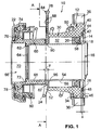
- Fig. 1
- eine Längsschnittansicht durch einen erfindungsgemäß ausgebildeten Zentralausrücker mit montiertem Sicherungselement,
- Fig. 2
- eine Schnittansicht des in Fig. 1 dargestellten Zentralausrückers entsprechend dem Schnittverlauf A-A in Fig. 1,
- Fig. 3
- eine perspektivische Darstellung des in Fig. 1 gezeigten Zentralausrückers mit montiertem Sicherungselement und
- Fig. 4
- eine perspektivische Darstellung des in Fig. 1 gezeigten Zentralausrückers mit abgenommenem Sicherungselement.
- Fig. 1
- 2 shows a longitudinal sectional view through a central release device designed according to the invention with a mounted securing element,
- Fig. 2
- 2 shows a sectional view of the central release device shown in FIG. 1 in accordance with the sectional profile AA in FIG. 1,
- Fig. 3
- a perspective view of the central release shown in Fig. 1 with the securing element and
- Fig. 4
- a perspective view of the central release shown in Fig. 1 with the securing element removed.
In den Figuren ist ein Zentralausrücker 10 für eine hydraulische
Kupplungsbetätigung für Trockenreibkupplungen im nicht
montierten Zustand in Grundstellung dargestellt. Der Zentralausrücker
10 weist ein Gehäuse 12 aus Kunststoff auf und hat
eine mit einem kreisringförmigen radialen Flansch 14 versehene
Hülse 16, die aus einem Stahlblech gezogen ist. Das Gehäuse 12
und die Hülse 16 begrenzen zusammen einen Druckraum 18, in dem
ein Ringkolben 20 aufgenommen ist. Ein auf der Hülse 16 geführtes
Ausrücklager 22 ist in an sich bekannter Weise mittels des
Ringkolbens 20 verschiebbar, um eine nicht dargestellte Kupplung
auszurücken. Das Gehäuse 12 und das Ausrücklager 22 sind
durch eine Feder 24, im vorliegenden Fall eine Schraubendruckfeder,
auseinander gespannt, die das Gehäuse 12 mit einer auf
den Flansch 14 gerichteten Kraft beaufschlagt. Zwischen dem Gehäuse
12 und dem Flansch 14 ist eine Dichtung 26 zur Abdichtung
des Druckraums 18 angeordnet. Ein für den Betrieb des Zentralausrückers
10 abnehmbares Sicherungselement, im dargestellten
Ausführungsbeispiel ein vorzugsweise aus Kunststoff bestehender,
flacher Querschieber 28, bildet im unmontierten Zustand
des Zentralausrückers 10 einen Anschlag für das Gehäuse 12 aus
und hindert das Gehäuse 12 alleine daran, sich entgegen der
Kraft der Feder 24 über einen vorbestimmten Betrag hinaus vom
Flansch 14 der Hülse 16 wegzubewegen, wie noch näher beschrieben
werden wird.In the figures, a
Das Gehäuse 12 hat einen im wesentlichen hohlzylindrischen Wandungsabschnitt
30, der eine zentrale Durchgangsbohrung 32 mit
konstantem Durchmesser aufweist und an seinem in Fig. 1 rechten
Ende in einen in der Draufsicht im wesentlichen runden Befestigungsflansch
34 übergeht. Der Befestigungsflansch 34 ist gemäß
Fig. 2 am Außenumfang mit drei symmetrisch verteilten Befestigungsaugen
36 versehen, die im Kraftfahrzeug der Befestigung
des Zentralausrückers 10 an einer Getriebewand bzw. einem Getriebedeckel
(nicht dargestellt) mittels beispielsweise Schrauben
(nicht dargestellt) dienen, welche die Befestigungsaugen 36
durchgreifen. Ferner ist am Gehäuse 12 ein Hydraulikanschluß 38
vorgesehen, der über eine Bohrung (nicht dargestellt) mit dem
Druckraum 18 verbunden ist, um die Zufuhr von Hydraulikflüssigkeit
zum Druckraum 18 hin zu gestatten.The
Die vom Wandungsabschnitt 30 des Gehäuses 12 abgewandte, zur
zentrierten Befestigung des Zentralausrückers 10 an der Getriebewand
bzw. dem Getriebedeckel ausgebildete Stirnfläche 40 des
Befestigungsflansches 34 ist mittig mit einer Zentriersenkung
42 versehen, deren Umfangsfläche 44 der radialen Zentrierung
des Flansches 14 der Hülse 16 am Gehäuse 12 dient. Die ebene,
kreisringförmige Stirnfläche 46 der Zentriersenkung 42 weist
eine in axialer Richtung eingebrachte Ringnut 48 mit einer
Tiefe x zur Aufnahme der ringförmigen, vorzugsweise elastomeren
Dichtung 26 auf. In Fig. 1 ist die Dichtung 26 zur Verdeutlichung
ihrer tatsächlichen Abmaße im unverformten Zustand dargestellt.
Es ist ersichtlich, daß die Dichtung 26 im unverformten
Zustand um einen vorbestimmten Betrag dicker ist als die
Tiefe x der Ringnut 48, so daß die Dichtung 26 im montierten
Zustand des Zentralausrückers 10, in dem der Flansch 14 der
Hülse 16 infolge seiner nicht dargestellten Anlage an der Getriebewand
bzw. dem Getriebedeckel flächig an die Stirnfläche
46 der Zentriersenkung 42 des Gehäuses 12 gedrückt wird, in die
Ringnut 48 gepreßt wird und den Druckraum 18 zuverlässig abdichtet.
Aus der obigen Beschreibung wird deutlich, daß die
Hülse 16 mit ihrem Flansch 14 zwar in bzw. an der Zentriersenkung
42 des Gehäuses 12 zentriert wird; eine feste Verbindung
zwischen Hülse 16 und Gehäuse 12 ist indes nicht vorhanden.The facing away from the
Zum vorzugsweise formgespritzten Gehäuse 12 ist schließlich
noch anzumerken, daß an dem Befestigungsflansch 34 auf der von
der Zentriersenkung 42 abgewandten Seite ein im wesentlichen
ringförmiges Widerlager 50 für die Feder 24 ausgebildet ist,
während der Wandungsabschnitt 30 des Gehäuses 12 stirnseitig,
d.h. in Fig. 1 auf der linken Seite mit einer ebenen Kreisringfläche
52 abschließt, die eine Anschlagfläche für den Querschieber
28 ausbildet.Finally, to the preferably injection molded
An den Flansch 14 der Hülse 16 schließt sich ein langgestreckter,
hohlzylindrischer Hülsenabschnitt 54 an, der sich koaxial
zur Durchgangsbohrung 32 des Gehäuse 12 über die gesamte Länge
der Durchgangsbohrung 32 und darüber hinaus erstreckt. Im montierten
Zustand des Zentralausrückers 10 ist die Kupplungs- bzw.
Getriebewelle (nicht dargestellt) durch den Hülsenabschnitt
54 hindurch geführt. Die Außenumfangsfläche 56 des Hülsenabschnitts
54 bildet eine Lauf- bzw. Führungsfläche sowohl
für den metallischen Ringkolben 20, an dem druckraumseitig ein
in Fig. 1 im unverformten Zustand dargestelltes, elastomeres
Dichtelement 58 befestigt ist, welches an der Durchgangsbohrung
32 des Gehäuses 12 und an der Außenumfangsfläche 56 der Hülse
16 anliegt, als auch für eine Schiebehülse 60 aus Kunststoff
aus, die das Ausrücklager 22 trägt. Am in Fig. 1 linken, vom
Flansch 14 abgewandten Ende hat die Hülse 16 schließlich einen
vom Hülsenabschnitt 54 radial nach innen vorstehenden Kragen
62, welcher der Befestigung eines Blechrings 64 dient, der
einen Anschlag für die Schiebehülse 60 ausbildet, wie noch beschrieben
werden wird. At the
Die vom Ringkolben 20 getrennte Schiebehülse 60 hat eine gestufte
Durchgangsbohrung 66 mit einem durchmesserkleineren Abschnitt
68, an dem die Schiebehülse 60 auf der Außenumfangsfläche
56 des Hülsenabschnitts 54 gleitend geführt ist, derart,
daß die Schiebehülse 60 in den axialen Ringspalt zwischen der
Durchgangsbohrung 32 des Gehäuses 12 und der Außenumfangsfläche
56 der Hülse 16 eintauchen kann, um stirnseitig mit dem Ringkolben
20 in Wirkeingriff zu kommen. Ferner weist die gestufte
Durchgangsbohrung 66 am freien Ende der Schiebehülse 60 einen
durchmessergrößeren Abschnitt 70 auf, der mit dem durchmesserkleineren
Abschnitt 68 einen Absatz 72 ausbildet, welcher als
Anschlagfläche dient, mit der die Schiebehülse 60 an dem am
Kragen 62 des Hülsenabschnitts 54 form- und kraftschlüssig befestigten
Blechring 64 anschlagen kann, welcher über die Außenumfangsfläche
56 des Hülsenabschnitts 54 nach radial außen
übersteht, zum durchmessergrößeren Abschnitt 70 der gestuften
Durchgangsbohrung 66 aber noch ein geringfügiges Radialspiel
hat. Im Ergebnis hält der einmal montierte Blechring 64 die
Schiebehülse 60 an der Hülse 16 bzw. verhindert, daß die Schiebehülse
60 von der Hülse 16 abgezogen werden kann.The sliding
Am Außenumfang der Schiebehülse 60 ist ein an sich bekanntes
Ausrücklager 22 mit seinem Innenring 74 gegen einen Bund 76 der
Schiebehülse 60 mittels eines Sicherungsrings 78 befestigt.
Schließlich ist am Innenring 74 des Ausrücklagers 22 ein weiteres
ringförmiges, aus Kunststoff bestehendes Widerlager 80 für
die Feder 24 form- und kraftschlüssig festgelegt.On the outer circumference of the sliding
In der dargestellten Grundstellung des Zentralausrückers 10
spannt die zwischen den Widerlagern 50, 80 unter Vorspannung
eingefügte Feder 24 das Gehäuse 12 und das Ausrücklager 22 auf
der Hülse 16 in axialer Richtung derart auseinander, daß auf
der in Fig. 1 rechten Seite das Gehäuse 12 mit seiner Stirnfläche
46 bzw. der Dichtung 26 gegen den Flansch 14 der Hülse 16
gedrückt bzw. der Flansch 14 der Hülse 16 in Richtung der
Stirnfläche 46 des Gehäuses 12 gezogen wird, während auf der in
Fig. 1 linken Seite die Schiebehülse 60 mit ihrem Absatz 72
über das Widerlager 80, den Innenring 74 des Ausrücklagers 22
und den Sicherungsring 78 auf Anschlag gegen den am Hülsenabschnitt
54 befestigten Blechring 64 gehalten wird. Um bei der
Montage, dem Verpacken, der Lagerung bzw. dem Transport nun zu
verhindern, daß sich das Gehäuse 12 gegen die relativ kleine
Kraft der Feder 24 vom Flansch 14 der Hülse 16 unbeabsichtigt
wegbewegt, wobei die Dichtung 26 und/oder das Dichtelement 58
beschädigt werden könnten, ist der für den Betrieb des Zentralausrückers
10 abnehmbare Querschieber 28 vorgesehen, der im
dargestellten Ausführungsbeispiel in einem radialen Ringspalt
82 vorbestimmter Breite y zwischen der Kreisringfläche 52 des
Gehäuses 12 und der Schiebehülse 60 an der Außenumfangsfläche
56 des Hülsenabschnitts 54 der Hülse 16 form- und kraftschlüssig
festgelegt werden kann.In the illustrated basic position of the
In den Fig. 2, 3 und 4 ist der vorzugsweise aus Kunststoff gefertigte
Querschieber 28 deutlich zu erkennen. Gemäß insbesondere
Fig. 2 weist der an seinen Kanten allseits abgerundete
Querschieber 28 einen Griffteil 84 auf, von dem sich zwei
Schenkel 86 wegerstrecken, die in der Draufsicht gesehen im
wesentlichen die Form eines C's bilden. Der sich in Richtung
der Schenkel 86 in der Draufsicht geringfügig verjüngende
Griffteil 84 ist zur besseren Handhabung des Querschiebers 28
auf beiden Seiten mit jeweils einem Profil 88 versehen, wie in
Fig. 1 gezeigt ist. Die über ihre Länge eine im wesentlichen
konstante Breite aufweisenden Schenkel 86 des Querschiebers 28
sind nach außen elastisch auffederbar und bilden eine teilzylindrische
Innenumfangsfläche 90 aus, deren Durchmesser d im
wesentlichen dem Durchmesser der Außenumfangsfläche 56 des
Hülsenabschnitts 54 entspricht. Dabei ist der lichte Abstand a
der Schenkelenden 92 geringfügig kleiner als der Durchmesser d
der teilzylindrischen Innenumfangsfläche 90, so daß der Quer-schieber
28 im montierten Zustand den Hülsenabschnitt 54 der
Hülse 16 in der Art einer Schnappverbindung hintergreift, wie
in Fig. 2 gut zu erkennen ist. Um das Fügen des Querschiebers
28 in einer zur Längsachse des Zentralausrückers 10 senkrechten,
in Fig. 4 durch einen Doppelpfeil angedeuteten Richtung zu
erleichtern, sind die Schenkelenden 92 auf den einander zugewandten
Seiten mit jeweils einer Fügeschräge 94 versehen.2, 3 and 4 is preferably made of
Zur Montage am Zentralausrücker 10 wird der Querschieber 28
zwischen den Windungen der Feder 24 hindurch in den Ringspalt
82 zwischen Gehäuse 12 und Schiebehülse 60 geschoben, bis die
Fügeschrägen 94 an den Schenkelenden 92 des Querschieber 28 an
der Außenumfangsfläche 56 des Hülsenabschnitts 54 zur Anlage
gelangen. Bei einem weiteren Schieben des Querschiebers 28 in
Richtung der Längsachse des Zentralausrückers 10 werden die
Schenkel 86 vorübergehend aufgespreizt und schnappen hinter der
Außenumfangsfläche 56 des Hülsenabschnitts 54 wieder zusammen,
so daß der Querschieber 28 in radialer Richtung unter Anlage
der teilzylindrischen Innenumfangsfläche 90 an der Außenumfangsfläche
56 des Hülsenabschnitts 54 form- und kraftschlüssig
festliegt. In axialer Richtung des Zentralausrückers 10 gesehen
verhindert der Querschieber 28 nun, daß sich das Gehäuse 12
entgegen der Kraft der Feder 24 über einen vorbestimmten Betrag
hinaus vom Flansch 14 der Hülse 16 entfernen kann. Versucht man
das Gehäuse 12 entgegen der Kraft der Feder 24 vom Flansch 14
der Hülse 16 wegzudrücken, kommt das Gehäuse 12 mit der Kreisringfläche
52 des Wandungsabschnitts 30 am Querschieber 28 zur
Anlage, der sich seinerseits über die dem Querschieber 28 zugewandte,
ebene Kreisringfläche 96 der Schiebehülse 60 und den
Absatz 72 der Schiebehülse 60 an dem am Kragen 62 des Hülsenabschnitts
54 der Hülse 16 befestigten Blechring 64 abstützt.The
Die Demontage des Querschiebers 28, die für den Betrieb des
Zentralausrückers 10 natürlich notwendig ist, weil sich dabei
die Schiebehülse 60 in die Durchgangsbohrung 32 des Gehäuses 12
hinein bewegen muß, um mit dem Ringkolben 20 in Wirkverbindung
zu kommen, erfolgt analog in umgekehrter Richtung.The disassembly of the
Der eigentliche hydraulische Betrieb des Zentralausrückers 10
in dem im Kraftfahrzeug montierten Zustand ist hinlänglich bekannt.
Auf eine diesbezügliche Beschreibung wird daher an dieser
Stelle verzichtet.The actual hydraulic operation of the
Für den Fachmann ist ersichtlich, daß der vorbestimmte Betrag,
um den sich im unmontierten Zustand des Zentralausrückers 10
das Gehäuse 12 vom Flansch 14 der Hülse 16 wegbewegen kann, bis
es an einer weiteren Bewegung durch den Querschieber 28 gehindert
wird, konstruktiv ohne Probleme den jeweiligen Erfordernissen
entsprechend eingestellt werden kann, nämlich durch entsprechende
Wahl der Dicke des Querschiebers 28 und/oder durch
geeignete Einstellung der Breite y des Ringspalts 82, was sich
leicht durch entsprechende Wahl der axialen Länge des Gehäuses
12, der Hülse 16 und/oder der Schiebehülse 60 realisieren läßt.
Dabei sollte der vorbestimmte Betrag, um den sich im unmontierten
Zustand des Zentralausrückers 10 das Gehäuse 12 vom Flansch
14 der Hülse 16 wegbewegen kann, vorzugsweise kleiner oder
gleich der Tiefe x der Ringnut 48 gewählt werden, damit die
Dichtung 26 nicht aus der Ringnut 48 am Gehäuse 12 hinausgleiten
kann. Natürlich kann dieser vorbestimmte Betrag auch annähernd
Null betragen, so daß bei aufgestecktem Querschieber 28
im wesentlichen keine Relativbewegung zwischen Gehäuse 12 und
Hülse 16 mehr möglich ist.It will be apparent to those skilled in the art that the predetermined amount
around the in the unassembled state of the central release 10th
the
Im obigen Ausführungsbeispiel wurde beschrieben, daß der Querschieber
28 in dem Ringspalt 82 zwischen Gehäuse 12 und Schiebehülse
60 an der Hülse 16 form- und kraftschlüssig festgelegt
wird. Ebenso ist es aber möglich, daß der Querschieber 28 in
einer am Außenumfang der Schiebehülse 60 angebrachten Nut
(nicht dargestellt) oder an einem am Außenumfang der Schiebehülse
60 angebrachten Absatz (nicht dargestellt) an der Schiebehülse
60 form- und kraftschlüssig festlegt wird, was sich bei
einer konstruktiven Ausgestaltung des Zentralausrückers 10 anbieten
würde, bei der die Schiebehülse 60 auch in der Grundstellung
des Zentralausrückers 10 in die Durchgangsbohrung 32
des Gehäuses 12 eintaucht. Auch ist eine konstruktive Ausgestaltung
denkbar, bei der der Querschieber 28 in einer am Außenumfang
des Gehäuses 12 angebrachten Nut (nicht dargestellt)
oder an einem am Außenumfang des Gehäuses 12 angebrachten Absatz
(nicht dargestellt) am Gehäuse 12 form- und kraftschlüssig
festgelegt wird und dabei eine Anschlagfläche ausbildet für
eine an der Schiebehülse 60 befestigte, das Gehäuse 12 teleskopisch
umgebende Schutzhülse (nicht dargestellt) aus vorzugsweise
Kunststoff oder für ein an der Schiebehülse 60 bzw. dem
Ausrücklager 22 befestigtes, verlängertes Widerlager (nicht
dargestellt) für die Feder 24.In the above embodiment, it was described that the
Es wird ein Zentralausrücker für eine hydraulische Kupplungsbetätigung insbesondere für Kraftfahrzeuge offenbart, mit einem Gehäuse und einer mit einem Flansch versehenen Hülse, die zusammen einen Druckraum zur Aufnahme eines Ringkolbens begrenzen, mittels dessen ein auf der Hülse geführtes Ausrücklager verschiebbar ist. Dabei beaufschlagt eine Gehäuse und Ausrücklager auseinander spannende Feder das Gehäuse mit einer auf den Flansch gerichteten Kraft. Zwischen dem Gehäuse und dem Flansch ist ferner eine Dichtung zur Abdichtung des Druckraums angeordnet. Erfindungsgemäß ist ein für den Betrieb des Zentralausrückers abnehmbares Sicherungselement vorgesehen, das im unmontierten Zustand des Zentralausrückers einen Anschlag für das Gehäuse ausbildet und dieses alleine daran hindert, sich entgegen der Kraft der Feder über einen vorbestimmten Betrag hinaus vom Flansch der Hülse wegzubewegen. Somit wird ein einfach aufgebauter Zentralausrücker geschaffen, der verglichen mit dem Stand der Technik ohne die Gefahr von Funktionsproblemen günstiger herzustellen ist. It becomes a central release for hydraulic clutch actuation especially disclosed for motor vehicles, with a Housing and a flanged sleeve together limit a pressure chamber for receiving an annular piston, by means of which a release bearing is guided on the sleeve is movable. This applies a housing and release bearing spring apart the housing with one on the Flange directed force. Between the housing and the flange a seal for sealing the pressure chamber is also arranged. According to the invention is for the operation of the central release removable securing element is provided, which in the unmounted State of the central release a stop for that Forms housing and this alone prevents it from going against each other the force of the spring beyond a predetermined amount to move away from the flange of the sleeve. This makes it a simple one Central release created compared to that State of the art cheaper without the risk of functional problems is to be produced.
- 1010th
- ZentralausrückerCentral release
- 1212th
- Gehäusecasing
- 1414
- Flanschflange
- 1616
- HülseSleeve
- 1818th
- DruckraumPressure room
- 2020th
- RingkolbenRing piston
- 2222
- AusrücklagerRelease bearing
- 2424th
- Federfeather
- 2626
- Dichtungpoetry
- 2828
- QuerschieberCross slide
- 3030th
- WandungsabschnittWall section
- 3232
- DurchgangsbohrungThrough hole
- 3434
- BefestigungsflanschMounting flange
- 3636
- BefestigungsaugeMounting eye
- 3838
- HydraulikanschlußHydraulic connection
- 4040
- StirnflächeFace
- 4242
- ZentriersenkungCentering
- 4444
- UmfangsflächeCircumferential surface
- 4646
- StirnflächeFace
- 4848
- RingnutRing groove
- 5050
- WiderlagerAbutment
- 5252
- KreisringflächeCircular surface
- 5454
- HülsenabschnittSleeve section
- 5656
- AußenumfangsflächeOuter peripheral surface
- 5858
- DichtelementSealing element
- 6060
- SchiebehülseSliding sleeve
- 6262
- Kragencollar
- 6464
- BlechringSheet metal ring
- 6666
- gestufte Durchgangsbohrungstepped through hole
- 6868
- durchmesserkleinerer Abschnittsmaller diameter section
- 7070
- durchmessergrößerer Abschnittlarger diameter section
- 7272
- Absatzparagraph
- 7474
- Innenring Inner ring
- 7676
- BundFederation
- 7878
- SicherungsringCirclip
- 8080
- WiderlagerAbutment
- 8282
- RingspaltAnnular gap
- 8484
- GriffteilHandle part
- 8686
- Schenkelleg
- 8888
- Profilprofile
- 9090
- teilzylindrische Innenumfangsflächepartially cylindrical inner circumferential surface
- 9292
- SchenkelendeThigh end
- 9494
- FügeschrägeBevels
- 9696
- KreisringflächeCircular surface
- aa
- lichter Abstand der Schenkelenden 92Clearance of the leg ends 92
- dd
-
Durchmesser der Innenumfangsfläche 90Inner
circumferential surface diameter 90 - xx
-
Tiefe der Ringnut 48Depth of the
ring groove 48 - yy
-
Breite des Ringspalts 82Width of the
annular gap 82
Claims (11)
Applications Claiming Priority (2)
| Application Number | Priority Date | Filing Date | Title |
|---|---|---|---|
| DE19944083 | 1999-09-15 | ||
| DE19944083A DE19944083A1 (en) | 1999-09-15 | 1999-09-15 | Central release for hydraulic clutch actuation |
Publications (2)
| Publication Number | Publication Date |
|---|---|
| EP1085228A1 true EP1085228A1 (en) | 2001-03-21 |
| EP1085228B1 EP1085228B1 (en) | 2004-05-06 |
Family
ID=7922025
Family Applications (1)
| Application Number | Title | Priority Date | Filing Date |
|---|---|---|---|
| EP00118710A Expired - Lifetime EP1085228B1 (en) | 1999-09-15 | 2000-08-30 | Release device for hydraulic clutch actuator |
Country Status (4)
| Country | Link |
|---|---|
| US (1) | US6390267B1 (en) |
| EP (1) | EP1085228B1 (en) |
| AT (1) | ATE266160T1 (en) |
| DE (2) | DE19944083A1 (en) |
Cited By (1)
| Publication number | Priority date | Publication date | Assignee | Title |
|---|---|---|---|---|
| WO2008086763A1 (en) * | 2007-01-15 | 2008-07-24 | Luk Lamellen Und Kupplungsbau Beteiligungs Kg | Slave cylinder |
Families Citing this family (8)
| Publication number | Priority date | Publication date | Assignee | Title |
|---|---|---|---|---|
| DE10314864B3 (en) * | 2003-04-02 | 2004-10-28 | Fte Automotive Gmbh & Co. Kg | Central release for hydraulic clutch actuation |
| DE102010021788A1 (en) | 2010-05-27 | 2011-12-01 | Schaeffler Technologies Gmbh & Co. Kg | clutch release bearing |
| CN102777509A (en) * | 2011-05-13 | 2012-11-14 | 谢夫勒科技股份两合公司 | Improved hydraulic slave cylinder |
| DE102012212539A1 (en) | 2012-07-18 | 2014-01-23 | Schaeffler Technologies AG & Co. KG | clutch release bearing |
| DE102014001073A1 (en) | 2014-01-30 | 2015-07-30 | Fte Automotive Gmbh | Device for the hydraulic actuation of a motor vehicle friction clutch |
| DE102014212678B4 (en) * | 2014-07-01 | 2023-05-25 | Schaeffler Technologies AG & Co. KG | Transport lock for a concentric slave cylinder |
| CN107532658B (en) * | 2015-04-20 | 2020-01-14 | 舍弗勒技术股份两合公司 | Operating bearing |
| DE102018220400A1 (en) * | 2018-11-28 | 2020-05-28 | Zf Friedrichshafen Ag | Arrangement for actuating a clutch |
Citations (10)
| Publication number | Priority date | Publication date | Assignee | Title |
|---|---|---|---|---|
| US4344516A (en) * | 1979-04-20 | 1982-08-17 | Fichtel & Sachs Ag | Disengaging device |
| EP0095841B1 (en) | 1982-05-28 | 1986-08-06 | Automotive Products Public Limited Company | Clutch actuation arrangement for a motor vehicle transmission |
| EP0168932B1 (en) | 1984-06-13 | 1989-03-08 | LUCAS INDUSTRIES public limited company | Hydraulic slave cylinder |
| DE4109125A1 (en) | 1991-03-20 | 1992-09-24 | Fichtel & Sachs Ag | VACUUM-ASSISTED FILLING OF A HYDRAULIC CLUTCH ACTUATION |
| US5183141A (en) * | 1990-05-24 | 1993-02-02 | Kabushiki Kaisha Daikin Seisakusho | Release mechanism for pull-type clutch |
| DE4313346A1 (en) | 1993-04-23 | 1994-10-27 | Fichtel & Sachs Ag | Hydraulically operatable clutch release system |
| US5655639A (en) * | 1993-09-29 | 1997-08-12 | Valeo | Motor vehicle hydraulic clutch assembly of the pull to release type |
| FR2745616A1 (en) * | 1996-02-29 | 1997-09-05 | Valeo | Clutch release for motor vehicle diaphragm clutch |
| US5810145A (en) * | 1995-09-14 | 1998-09-22 | Valeo | Hydraulically controlled disengagement device for a clutch, notably for motor vehicles |
| DE19742468A1 (en) | 1997-09-26 | 1999-04-01 | Schaeffler Waelzlager Ohg | Slave cylinder housing made of plastic, into which a steel guide sleeve is inserted |
Family Cites Families (8)
| Publication number | Priority date | Publication date | Assignee | Title |
|---|---|---|---|---|
| DE3119367C1 (en) * | 1981-05-15 | 1982-12-09 | Bayerische Motoren Werke AG, 8000 München | Device for the hydraulic actuation of a drawn friction clutch for motor vehicles |
| GB2112490B (en) * | 1981-12-15 | 1985-07-03 | Automotive Products Plc | Hydraulic slave cylinder for a clutch release bearing |
| US4687084A (en) * | 1985-07-22 | 1987-08-18 | Automotive Products Plc | Clutch release apparatus for pull type clutches |
| DE4130525C2 (en) * | 1991-09-13 | 2000-05-18 | Mannesmann Sachs Ag | Fluid actuated release system |
| DE19622773C1 (en) | 1996-06-07 | 1997-05-07 | Fichtel & Sachs Ag | Slave cylinder for friction clutch actuation |
| DE19637903A1 (en) * | 1996-09-18 | 1998-03-19 | Mannesmann Sachs Ag | Device for indicating wear of a friction clutch |
| DE19754176B4 (en) * | 1997-12-06 | 2006-07-06 | Luk Lamellen Und Kupplungsbau Beteiligungs Kg | Guide surfaces in a slave cylinder, which are treated by shot peening |
| DE19811657A1 (en) * | 1998-03-18 | 1999-09-23 | Schaeffler Waelzlager Ohg | Vehicle hydraulic clutch disengaging system |
-
1999
- 1999-09-15 DE DE19944083A patent/DE19944083A1/en not_active Withdrawn
-
2000
- 2000-08-30 DE DE50006311T patent/DE50006311D1/en not_active Expired - Lifetime
- 2000-08-30 AT AT00118710T patent/ATE266160T1/en not_active IP Right Cessation
- 2000-08-30 EP EP00118710A patent/EP1085228B1/en not_active Expired - Lifetime
- 2000-09-13 US US09/661,172 patent/US6390267B1/en not_active Expired - Lifetime
Patent Citations (10)
| Publication number | Priority date | Publication date | Assignee | Title |
|---|---|---|---|---|
| US4344516A (en) * | 1979-04-20 | 1982-08-17 | Fichtel & Sachs Ag | Disengaging device |
| EP0095841B1 (en) | 1982-05-28 | 1986-08-06 | Automotive Products Public Limited Company | Clutch actuation arrangement for a motor vehicle transmission |
| EP0168932B1 (en) | 1984-06-13 | 1989-03-08 | LUCAS INDUSTRIES public limited company | Hydraulic slave cylinder |
| US5183141A (en) * | 1990-05-24 | 1993-02-02 | Kabushiki Kaisha Daikin Seisakusho | Release mechanism for pull-type clutch |
| DE4109125A1 (en) | 1991-03-20 | 1992-09-24 | Fichtel & Sachs Ag | VACUUM-ASSISTED FILLING OF A HYDRAULIC CLUTCH ACTUATION |
| DE4313346A1 (en) | 1993-04-23 | 1994-10-27 | Fichtel & Sachs Ag | Hydraulically operatable clutch release system |
| US5655639A (en) * | 1993-09-29 | 1997-08-12 | Valeo | Motor vehicle hydraulic clutch assembly of the pull to release type |
| US5810145A (en) * | 1995-09-14 | 1998-09-22 | Valeo | Hydraulically controlled disengagement device for a clutch, notably for motor vehicles |
| FR2745616A1 (en) * | 1996-02-29 | 1997-09-05 | Valeo | Clutch release for motor vehicle diaphragm clutch |
| DE19742468A1 (en) | 1997-09-26 | 1999-04-01 | Schaeffler Waelzlager Ohg | Slave cylinder housing made of plastic, into which a steel guide sleeve is inserted |
Cited By (1)
| Publication number | Priority date | Publication date | Assignee | Title |
|---|---|---|---|---|
| WO2008086763A1 (en) * | 2007-01-15 | 2008-07-24 | Luk Lamellen Und Kupplungsbau Beteiligungs Kg | Slave cylinder |
Also Published As
| Publication number | Publication date |
|---|---|
| DE19944083A1 (en) | 2001-04-12 |
| ATE266160T1 (en) | 2004-05-15 |
| DE50006311D1 (en) | 2004-06-09 |
| US6390267B1 (en) | 2002-05-21 |
| EP1085228B1 (en) | 2004-05-06 |
Similar Documents
| Publication | Publication Date | Title |
|---|---|---|
| EP1512882B1 (en) | Hydraulic cylinder | |
| DE102017001410A1 (en) | Self-adjusting pneumatic clutch actuator | |
| DE4339652A1 (en) | Hydraulic friction clutch actuator having brake fluid and mineral oil resistant seal | |
| WO2012155884A1 (en) | Hydraulically actuated clutch release unit with multipart housing | |
| WO2018001554A1 (en) | Master cylinder, in particular for a hydraulic clutch actuation device in motor vehicles | |
| DE19680491C5 (en) | Seals in a master cylinder | |
| DE19716473A1 (en) | Simplified vehicle clutch with central disengagement mechanism | |
| EP1085228B1 (en) | Release device for hydraulic clutch actuator | |
| DE19524312B4 (en) | Piston for a slave cylinder of a hydraulically actuated friction clutch | |
| DE102008058704A1 (en) | Hydraulic cylinder i.e. master cylinder, for use in hydraulic line for e.g. clutch actuation in motor vehicle, has housing including internal space with component having partial lengths, where one of lengths is sealingly covered by bellows | |
| EP1666753B1 (en) | Hydraulic cylinder, especially throw-out cylinder for hydraulic clutch actuation in vehicles | |
| DE102010054259B4 (en) | Master cylinder device | |
| EP3477157B1 (en) | Differential lock | |
| DE102017201411B4 (en) | Switching module for a differential lock, for a manual transmission or for an axle connection | |
| DE102009016284A1 (en) | Fastening arrangement for fastening slave cylinder housing of motor vehicle, has screw with threaded pin projected through socket, and flange exhibiting extension, which rises in direction of screw axis of screw from surface of flange | |
| DE19809852C2 (en) | Connection device for sanitary pipelines | |
| DE19636399A1 (en) | Pressure-operated ram for automotive diaphragm clutch | |
| EP3073127A1 (en) | Piston-sleeves component for an actuator which can be subjected to a pressurised medium, actuator which can be subjected to a pressurised medium and distributor gear | |
| WO1996023684A1 (en) | Hydraulic unit | |
| DE1530207C3 (en) | Hydraulically damped shock absorption device for railroad cars | |
| DE10107877A1 (en) | Hydraulic releasing device used in a motor vehicle for a clutch comprises a seal anchored on a holding ring fixed to a piston for common axial movement in both axial directions with the exception of the axial movement play formed in between | |
| DE3429492A1 (en) | Double-acting working cylinder | |
| DE4401030A1 (en) | Push-out device with hydraulic actuator, in particular for a clutch actuated by traction | |
| DE102005060869A1 (en) | Actuating arrangement for movable parts, especially flaps in motor vehicles, has gas spring and working cylinder arranged in series to form unit, whereby working piston is acted upon in deployment direction by gas piston rod | |
| DE3530565A1 (en) | STORAGE OF THE CLUTCH BODY OF A TRAILER COUPLING IN THE TRAVERSE |
Legal Events
| Date | Code | Title | Description |
|---|---|---|---|
| PUAI | Public reference made under article 153(3) epc to a published international application that has entered the european phase |
Free format text: ORIGINAL CODE: 0009012 |
|
| 17P | Request for examination filed |
Effective date: 20010120 |
|
| AK | Designated contracting states |
Kind code of ref document: A1 Designated state(s): AT BE CH CY DE DK ES FI FR GB GR IE IT LI LU MC NL PT SE |
|
| AX | Request for extension of the european patent |
Free format text: AL;LT;LV;MK;RO;SI |
|
| AKX | Designation fees paid |
Free format text: AT BE CH CY DE DK ES FI FR GB GR IE IT LI LU MC NL PT SE |
|
| GRAP | Despatch of communication of intention to grant a patent |
Free format text: ORIGINAL CODE: EPIDOSNIGR1 |
|
| GRAS | Grant fee paid |
Free format text: ORIGINAL CODE: EPIDOSNIGR3 |
|
| RAP1 | Party data changed (applicant data changed or rights of an application transferred) |
Owner name: FTEAUTOMOTIVE GMBH & CO. KG |
|
| GRAA | (expected) grant |
Free format text: ORIGINAL CODE: 0009210 |
|
| AK | Designated contracting states |
Kind code of ref document: B1 Designated state(s): AT BE CH CY DE DK ES FI FR GB GR IE IT LI LU MC NL PT SE |
|
| PG25 | Lapsed in a contracting state [announced via postgrant information from national office to epo] |
Ref country code: CY Free format text: LAPSE BECAUSE OF FAILURE TO SUBMIT A TRANSLATION OF THE DESCRIPTION OR TO PAY THE FEE WITHIN THE PRESCRIBED TIME-LIMIT Effective date: 20040506 Ref country code: NL Free format text: LAPSE BECAUSE OF FAILURE TO SUBMIT A TRANSLATION OF THE DESCRIPTION OR TO PAY THE FEE WITHIN THE PRESCRIBED TIME-LIMIT Effective date: 20040506 Ref country code: IE Free format text: LAPSE BECAUSE OF FAILURE TO SUBMIT A TRANSLATION OF THE DESCRIPTION OR TO PAY THE FEE WITHIN THE PRESCRIBED TIME-LIMIT Effective date: 20040506 Ref country code: FI Free format text: LAPSE BECAUSE OF FAILURE TO SUBMIT A TRANSLATION OF THE DESCRIPTION OR TO PAY THE FEE WITHIN THE PRESCRIBED TIME-LIMIT Effective date: 20040506 |
|
| REG | Reference to a national code |
Ref country code: GB Ref legal event code: FG4D Free format text: NOT ENGLISH |
|
| REG | Reference to a national code |
Ref country code: CH Ref legal event code: EP |
|
| REF | Corresponds to: |
Ref document number: 50006311 Country of ref document: DE Date of ref document: 20040609 Kind code of ref document: P |
|
| REG | Reference to a national code |
Ref country code: IE Ref legal event code: FG4D Free format text: GERMAN |
|
| PG25 | Lapsed in a contracting state [announced via postgrant information from national office to epo] |
Ref country code: SE Free format text: LAPSE BECAUSE OF FAILURE TO SUBMIT A TRANSLATION OF THE DESCRIPTION OR TO PAY THE FEE WITHIN THE PRESCRIBED TIME-LIMIT Effective date: 20040806 Ref country code: DK Free format text: LAPSE BECAUSE OF FAILURE TO SUBMIT A TRANSLATION OF THE DESCRIPTION OR TO PAY THE FEE WITHIN THE PRESCRIBED TIME-LIMIT Effective date: 20040806 Ref country code: GR Free format text: LAPSE BECAUSE OF FAILURE TO SUBMIT A TRANSLATION OF THE DESCRIPTION OR TO PAY THE FEE WITHIN THE PRESCRIBED TIME-LIMIT Effective date: 20040806 |
|
| PG25 | Lapsed in a contracting state [announced via postgrant information from national office to epo] |
Ref country code: ES Free format text: LAPSE BECAUSE OF FAILURE TO SUBMIT A TRANSLATION OF THE DESCRIPTION OR TO PAY THE FEE WITHIN THE PRESCRIBED TIME-LIMIT Effective date: 20040817 |
|
| PG25 | Lapsed in a contracting state [announced via postgrant information from national office to epo] |
Ref country code: LU Free format text: LAPSE BECAUSE OF NON-PAYMENT OF DUE FEES Effective date: 20040830 Ref country code: AT Free format text: LAPSE BECAUSE OF NON-PAYMENT OF DUE FEES Effective date: 20040830 |
|
| PG25 | Lapsed in a contracting state [announced via postgrant information from national office to epo] |
Ref country code: BE Free format text: LAPSE BECAUSE OF NON-PAYMENT OF DUE FEES Effective date: 20040831 Ref country code: CH Free format text: LAPSE BECAUSE OF NON-PAYMENT OF DUE FEES Effective date: 20040831 Ref country code: MC Free format text: LAPSE BECAUSE OF NON-PAYMENT OF DUE FEES Effective date: 20040831 Ref country code: LI Free format text: LAPSE BECAUSE OF NON-PAYMENT OF DUE FEES Effective date: 20040831 |
|
| GBT | Gb: translation of ep patent filed (gb section 77(6)(a)/1977) |
Effective date: 20040812 |
|
| NLV1 | Nl: lapsed or annulled due to failure to fulfill the requirements of art. 29p and 29m of the patents act | ||
| REG | Reference to a national code |
Ref country code: IE Ref legal event code: FD4D |
|
| ET | Fr: translation filed | ||
| BERE | Be: lapsed |
Owner name: FTE AUTOMOTIVE G.M.B.H. & CO. KG Effective date: 20040831 |
|
| PLBE | No opposition filed within time limit |
Free format text: ORIGINAL CODE: 0009261 |
|
| STAA | Information on the status of an ep patent application or granted ep patent |
Free format text: STATUS: NO OPPOSITION FILED WITHIN TIME LIMIT |
|
| REG | Reference to a national code |
Ref country code: CH Ref legal event code: PL |
|
| 26N | No opposition filed |
Effective date: 20050208 |
|
| REG | Reference to a national code |
Ref country code: GB Ref legal event code: 732E |
|
| REG | Reference to a national code |
Ref country code: FR Ref legal event code: TP Ref country code: FR Ref legal event code: CD |
|
| BERE | Be: lapsed |
Owner name: *FTE AUTOMOTIVE G.M.B.H. & CO. K.G. Effective date: 20040831 |
|
| PG25 | Lapsed in a contracting state [announced via postgrant information from national office to epo] |
Ref country code: PT Free format text: LAPSE BECAUSE OF NON-PAYMENT OF DUE FEES Effective date: 20041006 |
|
| REG | Reference to a national code |
Ref country code: FR Ref legal event code: PLFP Year of fee payment: 17 |
|
| REG | Reference to a national code |
Ref country code: FR Ref legal event code: PLFP Year of fee payment: 18 |
|
| PGFP | Annual fee paid to national office [announced via postgrant information from national office to epo] |
Ref country code: IT Payment date: 20170726 Year of fee payment: 18 |
|
| REG | Reference to a national code |
Ref country code: FR Ref legal event code: PLFP Year of fee payment: 19 |
|
| PG25 | Lapsed in a contracting state [announced via postgrant information from national office to epo] |
Ref country code: IT Free format text: LAPSE BECAUSE OF NON-PAYMENT OF DUE FEES Effective date: 20180830 |
|
| PGFP | Annual fee paid to national office [announced via postgrant information from national office to epo] |
Ref country code: DE Payment date: 20190807 Year of fee payment: 20 Ref country code: FR Payment date: 20190830 Year of fee payment: 20 |
|
| PGFP | Annual fee paid to national office [announced via postgrant information from national office to epo] |
Ref country code: GB Payment date: 20190821 Year of fee payment: 20 |
|
| REG | Reference to a national code |
Ref country code: DE Ref legal event code: R071 Ref document number: 50006311 Country of ref document: DE |
|
| REG | Reference to a national code |
Ref country code: GB Ref legal event code: PE20 Expiry date: 20200829 |
|
| PG25 | Lapsed in a contracting state [announced via postgrant information from national office to epo] |
Ref country code: GB Free format text: LAPSE BECAUSE OF EXPIRATION OF PROTECTION Effective date: 20200829 |