EP1084832A1 - Method and apparatus for printing elongate images on a web - Google Patents
Method and apparatus for printing elongate images on a web Download PDFInfo
- Publication number
- EP1084832A1 EP1084832A1 EP00112131A EP00112131A EP1084832A1 EP 1084832 A1 EP1084832 A1 EP 1084832A1 EP 00112131 A EP00112131 A EP 00112131A EP 00112131 A EP00112131 A EP 00112131A EP 1084832 A1 EP1084832 A1 EP 1084832A1
- Authority
- EP
- European Patent Office
- Prior art keywords
- printing
- web
- cylinder
- image portion
- printed
- Prior art date
- Legal status (The legal status is an assumption and is not a legal conclusion. Google has not performed a legal analysis and makes no representation as to the accuracy of the status listed.)
- Withdrawn
Links
- 238000007639 printing Methods 0.000 title claims abstract description 175
- 238000000034 method Methods 0.000 title claims description 13
- 238000005096 rolling process Methods 0.000 claims abstract description 6
- 230000002093 peripheral effect Effects 0.000 claims description 13
- 239000000463 material Substances 0.000 claims description 3
- 238000007645 offset printing Methods 0.000 description 7
- 238000009432 framing Methods 0.000 description 4
- 238000010276 construction Methods 0.000 description 3
- 238000005520 cutting process Methods 0.000 description 2
- 238000006073 displacement reaction Methods 0.000 description 2
- 238000004519 manufacturing process Methods 0.000 description 2
- 230000006978 adaptation Effects 0.000 description 1
- 230000004075 alteration Effects 0.000 description 1
- 230000002457 bidirectional effect Effects 0.000 description 1
- 230000008602 contraction Effects 0.000 description 1
- 238000010586 diagram Methods 0.000 description 1
- 230000000694 effects Effects 0.000 description 1
- 230000002349 favourable effect Effects 0.000 description 1
- 239000012530 fluid Substances 0.000 description 1
- 239000012634 fragment Substances 0.000 description 1
- 230000012447 hatching Effects 0.000 description 1
- 238000009434 installation Methods 0.000 description 1
- 238000007644 letterpress printing Methods 0.000 description 1
- 238000012986 modification Methods 0.000 description 1
- 230000004048 modification Effects 0.000 description 1
- 238000003860 storage Methods 0.000 description 1
- 239000002699 waste material Substances 0.000 description 1
Images


Classifications
-
- B—PERFORMING OPERATIONS; TRANSPORTING
- B41—PRINTING; LINING MACHINES; TYPEWRITERS; STAMPS
- B41F—PRINTING MACHINES OR PRESSES
- B41F13/00—Common details of rotary presses or machines
- B41F13/02—Conveying or guiding webs through presses or machines
- B41F13/04—Conveying or guiding webs through presses or machines intermittently
-
- B—PERFORMING OPERATIONS; TRANSPORTING
- B41—PRINTING; LINING MACHINES; TYPEWRITERS; STAMPS
- B41F—PRINTING MACHINES OR PRESSES
- B41F13/00—Common details of rotary presses or machines
- B41F13/48—Arrangements to enable printing to be effected over selected areas of a single forme cylinder
- B41F13/50—Arrangements to enable printing to be effected over selected areas of a single forme cylinder by effecting relative movement of forme and impression cylinders during printing cycle
-
- B—PERFORMING OPERATIONS; TRANSPORTING
- B41—PRINTING; LINING MACHINES; TYPEWRITERS; STAMPS
- B41P—INDEXING SCHEME RELATING TO PRINTING, LINING MACHINES, TYPEWRITERS, AND TO STAMPS
- B41P2213/00—Arrangements for actuating or driving printing presses; Auxiliary devices or processes
- B41P2213/70—Driving devices associated with particular installations or situations
- B41P2213/73—Driving devices for multicolour presses
- B41P2213/734—Driving devices for multicolour presses each printing unit being driven by its own electric motor, i.e. electric shaft
-
- B—PERFORMING OPERATIONS; TRANSPORTING
- B41—PRINTING; LINING MACHINES; TYPEWRITERS; STAMPS
- B41P—INDEXING SCHEME RELATING TO PRINTING, LINING MACHINES, TYPEWRITERS, AND TO STAMPS
- B41P2217/00—Printing machines of special types or for particular purposes
- B41P2217/50—Printing presses for particular purposes
- B41P2217/52—Printing presses for particular purposes for printing a long repeat length on webs
Definitions
- This invention relates to a web-fed printing press having at least two printing units in a row for printing an image whose dimension in the longitudinal direction of the web is longer than the circumference of the plate cylinder of each unit.
- the invention also deals with a method of printing such images on the web without intervening blanks between the printed images.
- Printing firms are sometimes requested by clients to produce printings as large as, say, from 70 inches (1778 millimeters) to 90 inches (2286 millimeters) in top-to-bottom dimension (i.e., dimension determined by the circumference of the printing cylinder, or dimension in the longitudinal direction of the web on which the printings are made).
- top-to-bottom dimension i.e., dimension determined by the circumference of the printing cylinder, or dimension in the longitudinal direction of the web on which the printings are made.
- outsize plate cylinders as well as blanket cylinders to match, with a diameter of 23.6 inches (600 millimeters) and thereabouts, for various sizes of printings to be made.
- Such outsize cylinders have been interchangeably mounted to printing presses as the need arises.
- Another known method involves the use of a relief or letterpress printing plate in the form of an endless belt running over a plate cylinder and a guide roller or rollers.
- the plate cylinder is, in fact, a sprocket having teeth for positive engagement in series of perforations formed in the side margins of the endless belt.
- the elongate image is imprinted from the belt on to the web running against an impression cylinder.
- the relief printing belt does, however, possess the weakness of being not so satisfactory in the quality of printing as that by offset printing.
- the printings made by this prior art method is also unsatisfactory in positional accuracy as the plate takes the form of an endless belt and is driven by the sprocket.
- the service life of the printing belt is questionable, too, by reason of the presence of the perforations in its side margins.
- This third prior art approach though definitely more favorable than the first two, has its own shortcomings. It had, first of all, limitations in the top-to-bottom dimension of the printings to be made. Since the plate cylinders of all the printings units were in constant rotation at the same peripheral speed as the running speed of the web, the spacings left unprinted by each printing unit were each equal to the circumference of each plate cylinder, or to an integral multiple thereof. The top-to-bottom dimension of each image thus printed, constituted of the sections printed by the respective units, was therefore limited to the total of the circumferences of all the plate cylinders if no blanks were to be left on the web.
- the present invention has it as an object to produce printings of practically any desired top-to-bottom dimension on a continuous web of paper or the like without creation of intervening blanks.
- the invention is applicable to a variety of printing presses built on different operating principles typically including offset printing.
- offset printing as is well known, the inked image is first printed on a blanket cylinder, from which the image is offset or transferred to the web running against an impression cylinder.
- the image is printed directly from the plate cylinder to the web also running against an impression cylinder. Therefore, in the following summary of the invention and in the claims appended hereto, the term "printing cylinder” will be used to refer both to the blanket cylinder of offset printing and to the plate cylinder of other printing principles.
- the present invention concerns, in a web-fed rotary printing press, a method of printing elongate images on a continuous web of paper or like material.
- the method presupposes use of a first printing unit wherein a first printing cylinder coacts with a first impression cylinder for printing on the web a first image portion having a first dimension, in the longitudinal direction of the web, that is not more than the circumference of the first printing cylinder, and a second printing unit wherein a second printing cylinder coacts with a second impression cylinder for printing on the web a second image portion having a second dimension, in the longitudinal direction of the web, that is not more than the circumference of the second printing cylinder.
- the first printing unit prints the first image portion on the web at prescribed spacings, by moving the first impression cylinder away from the first printing cylinder each time one first image portion is printed.
- the second printing unit prints the second image portion on the spacings left on the web by the first printing unit, also by moving the second impression cylinder away from the second printing cylinder each time one second image portion is printed.
- the printing cylinder of each printing unit is rotated, while each time the associated impression cylinder is held away therefrom for creation of a space on the web, at a variable speed through an angle necessary for causing the first or the second printing portion to be printed at the required spacings.
- each printing cylinder may be driven, when the impression cylinder is held away therefrom, faster or slower than when the impression cylinder is urged against the same via the web, and in relation to the traveling speed of the web.
- Such a variable speed rotation of the printing cylinder makes it possible for each printing unit to print the image portion at any desired spacings, which are to be, or have been, filled by the image portion printed by the other printing unit. Images can thus be printed on the web without intervening blanks.
- each image can be of a greater dimension in the longitudinal web direction than the circumference of the printing cylinder of either printing unit, up to the sum of the circumferences of the printing cylinders of both printing units.
- Another aspect of the invention concerns a printing press constructed for carrying the above summarized method into effect. All the necessary means according to the invention, including the variable speed motors for driving the printing cylinders, can be compactly and inexpensively built into a printing press of otherwise familiar construction.
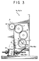
- the present invention is currently believed to be best applicable to the web-fed offset rotary printing press largely configured as depicted in FIG. 1 and therein generally designated 1.
- the machine 1 is shown to have three printing units 1a, 1b and 1c in a row, although the invention requires only two such units at a minimum.
- Each of the printing units 1a-1c conventionally comprises a plate cylinder 2, a blanket cylinder 3, and an impression cylinder 4.
- the plate cylinder 2 prints the inked image on the blanket cylinder 3, from which the image is offset to a continuous web 5 of paper or the like running against the impression cylinder 4.
- the plate cylinder 2, blanket cylinder 3, and impression cylinder 4 of each printing unit are mounted on shafts 2a, 3a and 4a, respectively, for joint rotation therewith.
- These shafts 2a-4a are rotatably mounted to and between a pair of framing walls 6a and 6b confronting each other across the path of the web 5.
- the plate cylinder 2 and blanket cylinder 3 of each printing unit are to be jointly rotated at a variable speed independently of the impression cylinder 4 while not printing on the web 5.
- a reference to both FIGS. 2 and 3 will reveal that two intermeshing gears 7 and 8 of the same diameter, tooth number, pitch, etc., are nonrotatably mounted on the shafts 2a and 3a of the plate cylinder 2 and blanket cylinder 3.
- Each printing unit is further provided with its own variable speed electric motor 9 for driving the plate cylinder 2 and blanket cylinder 3.
- a drive gear 10 is in constant mesh with the driven gear 7 on the plate cylinder shaft 2a and thence with the other driven gear 8 on the blanket cylinder shaft 3a.
- a driven gear 11 which is coupled via a gear train 13 to a gearbox 12 on the standard drive shaft driving the impression cylinders 4 of all the printing units 1a-1c as well as the various working parts of other processing stations of the press 1.
- the impression cylinder 4 is thus driven at the same peripheral speed as the traveling speed of the web 5.
- Each printing unit is intended to print a different part of an image on the web 5 at variable spacings.
- the creation of such unprinted spaces on the web requires that the impression cylinder 4 be movable into and out of rolling engagement with the blanket cylinder 3 via the web 5, the web being printed upon only while being pressed against the blanket cylinder by the impression cylinder.
- the impression cylinder 4 has its shaft 4a mounted to the pair of framing walls 6a and 6b via a pair of eccentric antifriction bearings 14a and 14b. These bearings are themselves rotatable relative to the framing walls 6a and 6b about a common axis O 1 , FIG. 2.
- the impression cylinder shaft 4a is supported eccentrically by the bearings 14a and 14b, so that the axis O 2 of rotation of the impression cylinder shaft relative to the bearings is off the axis O 1 of rotation of the bearings relative to the frame walls 6a and 6b.
- the joint extension and contraction of the cylinders 16a and 16b result in bidirectional rotation of the bearings 14a and 14b relative to the framing walls 6a and 6b, hence in the arcuate displacement of the impression cylinder shaft 4a about the axis O 1 of the bearings, and hence in the travel of the impression cylinder 4 into and out of rolling contact with the blanket cylinder 3.
- the web 5 may be fed into and through the successive printing units 1a-1c at a prescribed constant speed.
- the impression cylinders 4 of all the printing units may be maintained in rotation at the same peripheral speed as the running speed of the web 5 irrespective of whether the impression cylinders are held against or spaced from the blanket cylinders 3.
- the plate cylinders 2 and blanket cylinders 3 of the printing units 1a-1c are to be driven at the same peripheral speed as the running speed of the web 5 when the impression cylinders 4 are held against the blanket cylinders via the web, and at a higher or lower peripheral speed than the running speed of the web when the impression cylinders are retracted.
- the rotational speeds of the plate cylinders 2 and blanket cylinders 3 are individually controllable as aforesaid by the variable speed motors 9 provided one to each printing unit.
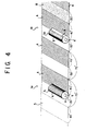
- each printing unit is each forty-five inches in circumference.
- each image to be printed is seventy inches in top-to-bottom dimension, and that each such image on the web 5 is to be constituted of a forty-inch first image portion, which is to be printed by the first printing unit 1a, and a thirty-inch second image portion to be printed by the second printing unit 1b.
- FIG. 4 the first image portions A which have been printed on the web 5 are indicated by hatching, and the second image portion B which has been printed on the web, by fine dots.
- This figure also shows, for clarity, only fragments of the blanket cylinders 3 1 and 3 2 of the printing units 1a and 1b in addition to the web 5.
- the first blanket cylinder 3 1 is therein shown just upon completion of printing one forty-inch first image portion A.
- the first blanket cylinder 3 1 has revolved from a to b through the greater part of its circumference, with the associated impression cylinder held against the same, for printing that one first image portion A.
- the next step is the creation, by the first printing unit 1a, of one thirty-inch spacing on the web, to be later filled in with a second image portion B by the second printing unit 1b.
- the impression cylinder of the first printing unit 1a must be held away from the first blanket cylinder 3 1 while the web 5 travels thirty inches.
- the first blanket cylinder 3 1 must rotate through an angle necessary for bringing the leading edge a of the first image portion printed thereon to the angular position exactly opposite the web 5 at the end of its thirty-inch travel. To this end the first blanket cylinder 3 1 must revolve from b to a through the smaller part of its circumference. This smaller circumferential part from b to a is five inches whereas the web 5 travels thirty inches. The peripheral speed of the first blanket cylinder 3 1 must therefore be less than the running speed of the web 5 by an amount corresponding to the twenty-five-inch difference.
- the impression cylinder 4 of the first printing unit 1a may be reactuated into rolling contact with the first blanket cylinder 3 1 via the web.
- the first blanket cylinder 3 1 may then be driven at the same peripheral speed as the traveling speed of the web. Another first image portion A will now be printed on the web.
- the foregoing cycle of operation may be repeated as the web continues running at prescribed speed.
- the first printing unit 1a will repeatedly print the forty-inch first image portion A on the web 5 at thirty-inch spacings.
- the second printing unit 1b is to print the second image portion B on the web blanks left between the first image portions A printed thereon by the first printing unit.
- the angular position of the blanket cylinder 3 2 of this second printing unit must be so preadjusted in relation to that of the first blanket cylinder 3 1 that the leading edge a' of the second image portion B on the second blanket cylinder 3 2 comes exactly opposite the web 5 when the trailing edge of each first image portion A printed on the web comes exactly opposite the second blanket cylinder.
- FIG. 4 shows the second blanket cylinder 3 2 in such an angular position with respect to the web 5. Then the associated impression cylinder may be actuated into contact with the second blanket cylinder 3 2 via the web 5, and the second blanket cylinder may be accelerated to the same peripheral speed as the running speed of the web, it being understood that the impression cylinder is in constant rotation at the same peripheral speed as the running speed of the web. The second image portion B will thus be printed on the web upon subsequent rotation of the second blanket cylinder 3 2 through an angle corresponding to thirty inches of its circumference.
- the impression cylinder 4 may be withdrawn from the second blanket cylinder 3 2 to skip over the next first image portion A printed on the web 5. Then, during the following forty-inch travel of the web 5, the second blanket cylinder 3 2 may be revolved through an angle corresponding to fifteen inches of its circumference.
- the blanket cylinders may be driven at a peripheral speed not necessarily lower, but higher, than the running speed of the web while the impression cylinder is held away therefrom, if the angular positions of the blanket cylinders are easier to control through such a higher speed rotation.
- the first blanket cylinder 3 1 may be rotated one complete revolution plus an angle corresponding to the difference between the circumference of the first blanket cylinder and the top-to-bottom dimension of the first image portion A.
- the second blanket cylinder 3 2 may likewise be rotated one complete revolution plus an angle corresponding to the difference between the circumference of the second printing cylinder and the top-to-bottom dimension of the second image portion B.
- Another possible departure from the illustrated embodiment is the driving of the impression cylinder 4 of each printing unit from the blanket cylinder 3 instead of from the gearbox 12.
- the impression cylinder can then be driven in total synchronism with the blanket cylinder, with the impression cylinder held geared to the blanket cylinder even when spaced therefrom.
- variable speed motor 9 It will also readily occur to the printing press specialists to drive the inking rollers, not shown, for the plate cylinder of each printing unit by the variable speed motor 9.
- the inking rollers may then be driven at the same peripheral speed as the plate cylinder 2 even though the peripheral speed of this plate cylinder is subject to change with that of the blanket cylinder.
Landscapes
- Engineering & Computer Science (AREA)
- Mechanical Engineering (AREA)
- Inking, Control Or Cleaning Of Printing Machines (AREA)
- Rotary Presses (AREA)
Applications Claiming Priority (2)
| Application Number | Priority Date | Filing Date | Title |
|---|---|---|---|
| JP26395599 | 1999-09-17 | ||
| JP26395599A JP4235960B2 (ja) | 1999-09-17 | 1999-09-17 | 長尺印刷物用印刷装置 |
Publications (1)
| Publication Number | Publication Date |
|---|---|
| EP1084832A1 true EP1084832A1 (en) | 2001-03-21 |
Family
ID=17396579
Family Applications (1)
| Application Number | Title | Priority Date | Filing Date |
|---|---|---|---|
| EP00112131A Withdrawn EP1084832A1 (en) | 1999-09-17 | 2000-06-06 | Method and apparatus for printing elongate images on a web |
Country Status (3)
| Country | Link |
|---|---|
| US (1) | US6327975B1 (enExample) |
| EP (1) | EP1084832A1 (enExample) |
| JP (1) | JP4235960B2 (enExample) |
Cited By (4)
| Publication number | Priority date | Publication date | Assignee | Title |
|---|---|---|---|---|
| US8141489B2 (en) | 2007-06-28 | 2012-03-27 | Goss International Americas, Inc. | Variable cutoff printing unit and method of printing |
| US8161874B2 (en) | 2007-06-28 | 2012-04-24 | Goss International Americas, Inc. | Variable cutoff printing unit with belt blanket and method of printing |
| CN102497989A (zh) * | 2009-09-21 | 2012-06-13 | 高斯国际美洲公司 | 自动转印过程中印刷机滚筒的加速与定相方法 |
| US8291821B2 (en) | 2008-10-09 | 2012-10-23 | Goss International Americas, Inc. | Infinitely variable cutoff printing press with constant speed plate cylinder and inker |
Families Citing this family (15)
| Publication number | Priority date | Publication date | Assignee | Title |
|---|---|---|---|---|
| JP2002234139A (ja) * | 2001-02-09 | 2002-08-20 | Nishioka Seisakusho:Kk | 輪転印刷機 |
| US6796239B2 (en) * | 2001-03-22 | 2004-09-28 | Heidelberger Druckmaschinen Ag | Method and device for driving a printing press |
| JP3616604B2 (ja) * | 2002-03-08 | 2005-02-02 | 株式会社東京機械製作所 | 印刷胴の軸受装置 |
| JP2004025526A (ja) * | 2002-06-24 | 2004-01-29 | Dainippon Screen Mfg Co Ltd | 印刷装置 |
| JP4276010B2 (ja) * | 2003-07-24 | 2009-06-10 | 株式会社小森コーポレーション | 印刷機における駆動装置 |
| US7270057B2 (en) * | 2004-01-28 | 2007-09-18 | Rdp Marathon Inc. | Rolling element adjustment system |
| DE102004026890A1 (de) * | 2004-05-26 | 2005-12-22 | Steuer Gmbh Printing Technology | Prägemaschine |
| JP4642067B2 (ja) * | 2007-12-27 | 2011-03-02 | 株式会社ミヤコシ | 電子写真印刷機 |
| US20090266250A1 (en) * | 2008-04-28 | 2009-10-29 | Goss International Americas, Inc. | Infinitely variable cut off printing press and method of varying cut off |
| US20090266251A1 (en) * | 2008-04-28 | 2009-10-29 | Goss International Americas, Inc. | Variable cut off printing press having flexible plate and blanket |
| US8122826B2 (en) * | 2008-04-28 | 2012-02-28 | Goss International Americas, Inc. | Infinitely variable cut off printing press |
| US8056475B2 (en) | 2008-11-05 | 2011-11-15 | Goss International Americas, Inc. | Variable cutoff printing press with common blanket cylinder |
| EP2367690A4 (en) * | 2008-11-13 | 2012-08-22 | Rtdt Llc | OFFSET PRINTING UNIT WITH PLATE HOLDER CYLINDER DRIVE |
| JP5582697B2 (ja) * | 2008-12-15 | 2014-09-03 | 日本リライアンス株式会社 | 印刷装置及び印刷方法 |
| JP2010247342A (ja) * | 2009-04-10 | 2010-11-04 | Mitsubishi Heavy Ind Ltd | 印刷機および印刷機の制御方法 |
Citations (5)
| Publication number | Priority date | Publication date | Assignee | Title |
|---|---|---|---|---|
| DE116450C (enExample) * | ||||
| FR980734A (fr) * | 1943-02-16 | 1951-05-17 | Procédé et dispositif d'impression offset en continu | |
| US4108067A (en) * | 1972-08-31 | 1978-08-22 | Veb Polygraph Leipzig | Method and apparatus for continuously printing uncased folded books |
| DE4104209A1 (de) * | 1991-02-12 | 1992-08-13 | Majer Christian Gmbh Co Kg | Verfahren und vorrichtung zum bedrucken von folienbahnen |
| WO1995020488A1 (en) * | 1994-01-31 | 1995-08-03 | Nilpeter A/S | A method of processing a continuous web extending along a predetermined path |
Family Cites Families (9)
| Publication number | Priority date | Publication date | Assignee | Title |
|---|---|---|---|---|
| DE3117663C2 (de) * | 1981-05-05 | 1984-09-20 | M.A.N.- Roland Druckmaschinen AG, 6050 Offenbach | Rollenrotationsdruckmaschine |
| US4805111A (en) * | 1985-11-27 | 1989-02-14 | Moore Business Forms, Inc. | Size independent modular web processing line and modules |
| USRE34483E (en) * | 1986-05-14 | 1993-12-21 | Strachan Henshaw Machinery Limited | Processing paper and other webs |
| JPH0833125B2 (ja) | 1987-01-30 | 1996-03-29 | 日産自動車株式会社 | 内燃機関の燃料供給制御装置 |
| US4860649A (en) * | 1988-09-26 | 1989-08-29 | Popkin Leonard I | Offset press with adjustable axle-bearing assembly for impression cylinder |
| US5289770A (en) * | 1992-09-18 | 1994-03-01 | Heidelberg Harris Gmbh | Device for presetting a cut-off register in a folder of a web-fed printing press |
| US5787807A (en) * | 1994-05-17 | 1998-08-04 | Heidelberger Druckmaschinen Ag | Sheet-fed rotary printing press with digital imaging |
| US5813336A (en) * | 1995-12-22 | 1998-09-29 | Heidelberger Druckmaschinen Ag | Printing unit with axially removable printing sleeves |
| US5771811A (en) * | 1996-10-10 | 1998-06-30 | Hurletron, Incorporated | Pre-registration system for a printing press |
-
1999
- 1999-09-17 JP JP26395599A patent/JP4235960B2/ja not_active Expired - Fee Related
-
2000
- 2000-06-06 EP EP00112131A patent/EP1084832A1/en not_active Withdrawn
- 2000-06-08 US US09/589,203 patent/US6327975B1/en not_active Expired - Lifetime
Patent Citations (5)
| Publication number | Priority date | Publication date | Assignee | Title |
|---|---|---|---|---|
| DE116450C (enExample) * | ||||
| FR980734A (fr) * | 1943-02-16 | 1951-05-17 | Procédé et dispositif d'impression offset en continu | |
| US4108067A (en) * | 1972-08-31 | 1978-08-22 | Veb Polygraph Leipzig | Method and apparatus for continuously printing uncased folded books |
| DE4104209A1 (de) * | 1991-02-12 | 1992-08-13 | Majer Christian Gmbh Co Kg | Verfahren und vorrichtung zum bedrucken von folienbahnen |
| WO1995020488A1 (en) * | 1994-01-31 | 1995-08-03 | Nilpeter A/S | A method of processing a continuous web extending along a predetermined path |
Cited By (4)
| Publication number | Priority date | Publication date | Assignee | Title |
|---|---|---|---|---|
| US8141489B2 (en) | 2007-06-28 | 2012-03-27 | Goss International Americas, Inc. | Variable cutoff printing unit and method of printing |
| US8161874B2 (en) | 2007-06-28 | 2012-04-24 | Goss International Americas, Inc. | Variable cutoff printing unit with belt blanket and method of printing |
| US8291821B2 (en) | 2008-10-09 | 2012-10-23 | Goss International Americas, Inc. | Infinitely variable cutoff printing press with constant speed plate cylinder and inker |
| CN102497989A (zh) * | 2009-09-21 | 2012-06-13 | 高斯国际美洲公司 | 自动转印过程中印刷机滚筒的加速与定相方法 |
Also Published As
| Publication number | Publication date |
|---|---|
| JP4235960B2 (ja) | 2009-03-11 |
| JP2001080053A (ja) | 2001-03-27 |
| US6327975B1 (en) | 2001-12-11 |
Similar Documents
| Publication | Publication Date | Title |
|---|---|---|
| US6327975B1 (en) | Method and apparatus for printing elongate images on a web | |
| US5787811A (en) | Flexographic printing press | |
| US4606269A (en) | Register adjustment device for a rotary printing machine | |
| US3323452A (en) | Variable cut-off web offset press | |
| US6041706A (en) | Complete release blanket | |
| GB2146291A (en) | Rotary printing press | |
| JP2964238B2 (ja) | オフセット印刷機構及びこの印刷機構を有するオフセット印刷機 | |
| CN101925461A (zh) | 印刷机的输墨装置 | |
| US5383393A (en) | Multicolor lithographic rotary press | |
| EP0267007A2 (en) | An apparatus for controlling paper transfer speed of printing section of a form printing machine | |
| US5706725A (en) | Flexographic printing press with variable printing length | |
| US3541953A (en) | Apparatus for production of printed web materials | |
| EP1371592B1 (en) | Printing-speed-responsive jaw spacing adjustment system for a jaw cylinder at the folding station of a web-fed printing press | |
| EP0325445A2 (en) | Printing machines | |
| JP3889824B2 (ja) | 印刷機械のインキ装置を調整するための方法及び装置 | |
| EP0292492B1 (en) | Printing apparatus | |
| DE9311113U1 (de) | Eindruckwerk für fliegend wechselnde Eindrucke | |
| US5159878A (en) | System for moving a plate cylinder relative to a blanket cylinder | |
| US5706728A (en) | Printing apparatus | |
| DE10259495B4 (de) | Farbwerk einer Druckmaschine | |
| JP4318109B2 (ja) | フォーム印刷機における印刷部の紙送り速度調整装置 | |
| JP3795054B2 (ja) | 個別駆動式印刷機械の制御方法及び個別駆動式印刷機械 | |
| US4552067A (en) | Rotary printing machine with offset bearing and drive for an exchange cylinder | |
| CN101108550B (zh) | 交换滚筒型轮转机 | |
| JP4460852B2 (ja) | 印刷機の位相調整装置 |
Legal Events
| Date | Code | Title | Description |
|---|---|---|---|
| PUAI | Public reference made under article 153(3) epc to a published international application that has entered the european phase |
Free format text: ORIGINAL CODE: 0009012 |
|
| AK | Designated contracting states |
Kind code of ref document: A1 Designated state(s): DE FR GB IT NL SE |
|
| AX | Request for extension of the european patent |
Free format text: AL;LT;LV;MK;RO;SI |
|
| 17P | Request for examination filed |
Effective date: 20010505 |
|
| AKX | Designation fees paid |
Free format text: DE FR GB IT NL SE |
|
| 17Q | First examination report despatched |
Effective date: 20030916 |
|
| STAA | Information on the status of an ep patent application or granted ep patent |
Free format text: STATUS: THE APPLICATION IS DEEMED TO BE WITHDRAWN |
|
| 18D | Application deemed to be withdrawn |
Effective date: 20040103 |