EP1083992B1 - Support de reacteur a plusieurs chambres de reception de microechantillons - Google Patents
Support de reacteur a plusieurs chambres de reception de microechantillons Download PDFInfo
- Publication number
- EP1083992B1 EP1083992B1 EP99927783A EP99927783A EP1083992B1 EP 1083992 B1 EP1083992 B1 EP 1083992B1 EP 99927783 A EP99927783 A EP 99927783A EP 99927783 A EP99927783 A EP 99927783A EP 1083992 B1 EP1083992 B1 EP 1083992B1
- Authority
- EP
- European Patent Office
- Prior art keywords
- plate
- reactor support
- shaped body
- recess
- sample
- Prior art date
- Legal status (The legal status is an assumption and is not a legal conclusion. Google has not performed a legal analysis and makes no representation as to the accuracy of the status listed.)
- Expired - Lifetime
Links
- 239000007788 liquid Substances 0.000 claims abstract description 50
- 239000002245 particle Substances 0.000 claims abstract description 26
- 238000011049 filling Methods 0.000 claims abstract description 14
- 238000012546 transfer Methods 0.000 claims description 7
- 239000011148 porous material Substances 0.000 claims description 6
- 238000009826 distribution Methods 0.000 claims description 5
- 239000011521 glass Substances 0.000 claims description 4
- 239000000919 ceramic Substances 0.000 claims description 3
- 239000008187 granular material Substances 0.000 claims description 3
- 239000004033 plastic Substances 0.000 claims description 3
- 229920003023 plastic Polymers 0.000 claims description 3
- 239000002184 metal Substances 0.000 claims description 2
- 230000000630 rising effect Effects 0.000 claims 2
- 239000000853 adhesive Substances 0.000 claims 1
- 230000009969 flowable effect Effects 0.000 claims 1
- 239000011888 foil Substances 0.000 claims 1
- 210000002500 microbody Anatomy 0.000 claims 1
- 229910021426 porous silicon Inorganic materials 0.000 claims 1
- 238000006243 chemical reaction Methods 0.000 description 13
- 238000000034 method Methods 0.000 description 7
- 238000000465 moulding Methods 0.000 description 5
- 230000015572 biosynthetic process Effects 0.000 description 4
- 238000012360 testing method Methods 0.000 description 4
- 238000005429 filling process Methods 0.000 description 3
- 238000012856 packing Methods 0.000 description 3
- -1 polyethylene Polymers 0.000 description 3
- 239000000126 substance Substances 0.000 description 3
- 238000003786 synthesis reaction Methods 0.000 description 3
- 239000011324 bead Substances 0.000 description 2
- 230000008901 benefit Effects 0.000 description 2
- 239000000969 carrier Substances 0.000 description 2
- 239000003153 chemical reaction reagent Substances 0.000 description 2
- 238000005516 engineering process Methods 0.000 description 2
- 239000012530 fluid Substances 0.000 description 2
- 239000012528 membrane Substances 0.000 description 2
- 230000008569 process Effects 0.000 description 2
- 238000000746 purification Methods 0.000 description 2
- 108091034117 Oligonucleotide Proteins 0.000 description 1
- 239000004698 Polyethylene Substances 0.000 description 1
- 239000004743 Polypropylene Substances 0.000 description 1
- JLCPHMBAVCMARE-UHFFFAOYSA-N [3-[[3-[[3-[[3-[[3-[[3-[[3-[[3-[[3-[[3-[[3-[[5-(2-amino-6-oxo-1H-purin-9-yl)-3-[[3-[[3-[[3-[[3-[[3-[[5-(2-amino-6-oxo-1H-purin-9-yl)-3-[[5-(2-amino-6-oxo-1H-purin-9-yl)-3-hydroxyoxolan-2-yl]methoxy-hydroxyphosphoryl]oxyoxolan-2-yl]methoxy-hydroxyphosphoryl]oxy-5-(5-methyl-2,4-dioxopyrimidin-1-yl)oxolan-2-yl]methoxy-hydroxyphosphoryl]oxy-5-(6-aminopurin-9-yl)oxolan-2-yl]methoxy-hydroxyphosphoryl]oxy-5-(6-aminopurin-9-yl)oxolan-2-yl]methoxy-hydroxyphosphoryl]oxy-5-(6-aminopurin-9-yl)oxolan-2-yl]methoxy-hydroxyphosphoryl]oxy-5-(6-aminopurin-9-yl)oxolan-2-yl]methoxy-hydroxyphosphoryl]oxyoxolan-2-yl]methoxy-hydroxyphosphoryl]oxy-5-(5-methyl-2,4-dioxopyrimidin-1-yl)oxolan-2-yl]methoxy-hydroxyphosphoryl]oxy-5-(4-amino-2-oxopyrimidin-1-yl)oxolan-2-yl]methoxy-hydroxyphosphoryl]oxy-5-(5-methyl-2,4-dioxopyrimidin-1-yl)oxolan-2-yl]methoxy-hydroxyphosphoryl]oxy-5-(5-methyl-2,4-dioxopyrimidin-1-yl)oxolan-2-yl]methoxy-hydroxyphosphoryl]oxy-5-(6-aminopurin-9-yl)oxolan-2-yl]methoxy-hydroxyphosphoryl]oxy-5-(6-aminopurin-9-yl)oxolan-2-yl]methoxy-hydroxyphosphoryl]oxy-5-(4-amino-2-oxopyrimidin-1-yl)oxolan-2-yl]methoxy-hydroxyphosphoryl]oxy-5-(4-amino-2-oxopyrimidin-1-yl)oxolan-2-yl]methoxy-hydroxyphosphoryl]oxy-5-(4-amino-2-oxopyrimidin-1-yl)oxolan-2-yl]methoxy-hydroxyphosphoryl]oxy-5-(6-aminopurin-9-yl)oxolan-2-yl]methoxy-hydroxyphosphoryl]oxy-5-(4-amino-2-oxopyrimidin-1-yl)oxolan-2-yl]methyl [5-(6-aminopurin-9-yl)-2-(hydroxymethyl)oxolan-3-yl] hydrogen phosphate Polymers Cc1cn(C2CC(OP(O)(=O)OCC3OC(CC3OP(O)(=O)OCC3OC(CC3O)n3cnc4c3nc(N)[nH]c4=O)n3cnc4c3nc(N)[nH]c4=O)C(COP(O)(=O)OC3CC(OC3COP(O)(=O)OC3CC(OC3COP(O)(=O)OC3CC(OC3COP(O)(=O)OC3CC(OC3COP(O)(=O)OC3CC(OC3COP(O)(=O)OC3CC(OC3COP(O)(=O)OC3CC(OC3COP(O)(=O)OC3CC(OC3COP(O)(=O)OC3CC(OC3COP(O)(=O)OC3CC(OC3COP(O)(=O)OC3CC(OC3COP(O)(=O)OC3CC(OC3COP(O)(=O)OC3CC(OC3COP(O)(=O)OC3CC(OC3COP(O)(=O)OC3CC(OC3COP(O)(=O)OC3CC(OC3COP(O)(=O)OC3CC(OC3CO)n3cnc4c(N)ncnc34)n3ccc(N)nc3=O)n3cnc4c(N)ncnc34)n3ccc(N)nc3=O)n3ccc(N)nc3=O)n3ccc(N)nc3=O)n3cnc4c(N)ncnc34)n3cnc4c(N)ncnc34)n3cc(C)c(=O)[nH]c3=O)n3cc(C)c(=O)[nH]c3=O)n3ccc(N)nc3=O)n3cc(C)c(=O)[nH]c3=O)n3cnc4c3nc(N)[nH]c4=O)n3cnc4c(N)ncnc34)n3cnc4c(N)ncnc34)n3cnc4c(N)ncnc34)n3cnc4c(N)ncnc34)O2)c(=O)[nH]c1=O JLCPHMBAVCMARE-UHFFFAOYSA-N 0.000 description 1
- 239000002313 adhesive film Substances 0.000 description 1
- 238000011166 aliquoting Methods 0.000 description 1
- 239000013566 allergen Substances 0.000 description 1
- 239000000427 antigen Substances 0.000 description 1
- 102000036639 antigens Human genes 0.000 description 1
- 108091007433 antigens Proteins 0.000 description 1
- 230000004888 barrier function Effects 0.000 description 1
- 239000012620 biological material Substances 0.000 description 1
- 230000008859 change Effects 0.000 description 1
- 238000004440 column chromatography Methods 0.000 description 1
- 230000000295 complement effect Effects 0.000 description 1
- 230000001419 dependent effect Effects 0.000 description 1
- 238000013461 design Methods 0.000 description 1
- 230000000694 effects Effects 0.000 description 1
- 238000000605 extraction Methods 0.000 description 1
- 238000001914 filtration Methods 0.000 description 1
- 238000002523 gelfiltration Methods 0.000 description 1
- 238000011005 laboratory method Methods 0.000 description 1
- 238000004519 manufacturing process Methods 0.000 description 1
- 239000000463 material Substances 0.000 description 1
- 229920000573 polyethylene Polymers 0.000 description 1
- 229920000642 polymer Polymers 0.000 description 1
- 229920001155 polypropylene Polymers 0.000 description 1
- 229920001343 polytetrafluoroethylene Polymers 0.000 description 1
- 239000004810 polytetrafluoroethylene Substances 0.000 description 1
- 239000005373 porous glass Substances 0.000 description 1
- 102000004196 processed proteins & peptides Human genes 0.000 description 1
- 108090000765 processed proteins & peptides Proteins 0.000 description 1
- 238000012545 processing Methods 0.000 description 1
- 238000003908 quality control method Methods 0.000 description 1
- 238000005070 sampling Methods 0.000 description 1
- 238000000926 separation method Methods 0.000 description 1
- 229910052710 silicon Inorganic materials 0.000 description 1
- 239000010703 silicon Substances 0.000 description 1
- 238000005245 sintering Methods 0.000 description 1
- 239000007787 solid Substances 0.000 description 1
- 239000007790 solid phase Substances 0.000 description 1
- 238000001179 sorption measurement Methods 0.000 description 1
- 230000007704 transition Effects 0.000 description 1
Images
Classifications
-
- B—PERFORMING OPERATIONS; TRANSPORTING
- B01—PHYSICAL OR CHEMICAL PROCESSES OR APPARATUS IN GENERAL
- B01L—CHEMICAL OR PHYSICAL LABORATORY APPARATUS FOR GENERAL USE
- B01L3/00—Containers or dishes for laboratory use, e.g. laboratory glassware; Droppers
- B01L3/50—Containers for the purpose of retaining a material to be analysed, e.g. test tubes
- B01L3/502—Containers for the purpose of retaining a material to be analysed, e.g. test tubes with fluid transport, e.g. in multi-compartment structures
- B01L3/5025—Containers for the purpose of retaining a material to be analysed, e.g. test tubes with fluid transport, e.g. in multi-compartment structures for parallel transport of multiple samples
- B01L3/50255—Multi-well filtration
-
- B—PERFORMING OPERATIONS; TRANSPORTING
- B01—PHYSICAL OR CHEMICAL PROCESSES OR APPARATUS IN GENERAL
- B01J—CHEMICAL OR PHYSICAL PROCESSES, e.g. CATALYSIS OR COLLOID CHEMISTRY; THEIR RELEVANT APPARATUS
- B01J19/00—Chemical, physical or physico-chemical processes in general; Their relevant apparatus
- B01J19/0046—Sequential or parallel reactions, e.g. for the synthesis of polypeptides or polynucleotides; Apparatus and devices for combinatorial chemistry or for making molecular arrays
-
- B—PERFORMING OPERATIONS; TRANSPORTING
- B01—PHYSICAL OR CHEMICAL PROCESSES OR APPARATUS IN GENERAL
- B01J—CHEMICAL OR PHYSICAL PROCESSES, e.g. CATALYSIS OR COLLOID CHEMISTRY; THEIR RELEVANT APPARATUS
- B01J2219/00—Chemical, physical or physico-chemical processes in general; Their relevant apparatus
- B01J2219/00274—Sequential or parallel reactions; Apparatus and devices for combinatorial chemistry or for making arrays; Chemical library technology
- B01J2219/00277—Apparatus
- B01J2219/00279—Features relating to reactor vessels
- B01J2219/00281—Individual reactor vessels
- B01J2219/00295—Individual reactor vessels the reactor vessels having pervious side walls
- B01J2219/00299—Generally cylindrical reactor vessels
-
- B—PERFORMING OPERATIONS; TRANSPORTING
- B01—PHYSICAL OR CHEMICAL PROCESSES OR APPARATUS IN GENERAL
- B01J—CHEMICAL OR PHYSICAL PROCESSES, e.g. CATALYSIS OR COLLOID CHEMISTRY; THEIR RELEVANT APPARATUS
- B01J2219/00—Chemical, physical or physico-chemical processes in general; Their relevant apparatus
- B01J2219/00274—Sequential or parallel reactions; Apparatus and devices for combinatorial chemistry or for making arrays; Chemical library technology
- B01J2219/00277—Apparatus
- B01J2219/00279—Features relating to reactor vessels
- B01J2219/00306—Reactor vessels in a multiple arrangement
- B01J2219/00308—Reactor vessels in a multiple arrangement interchangeably mounted in racks or blocks
- B01J2219/0031—Reactor vessels in a multiple arrangement interchangeably mounted in racks or blocks the racks or blocks being mounted in stacked arrangements
-
- B—PERFORMING OPERATIONS; TRANSPORTING
- B01—PHYSICAL OR CHEMICAL PROCESSES OR APPARATUS IN GENERAL
- B01J—CHEMICAL OR PHYSICAL PROCESSES, e.g. CATALYSIS OR COLLOID CHEMISTRY; THEIR RELEVANT APPARATUS
- B01J2219/00—Chemical, physical or physico-chemical processes in general; Their relevant apparatus
- B01J2219/00274—Sequential or parallel reactions; Apparatus and devices for combinatorial chemistry or for making arrays; Chemical library technology
- B01J2219/00277—Apparatus
- B01J2219/00351—Means for dispensing and evacuation of reagents
- B01J2219/00423—Means for dispensing and evacuation of reagents using filtration, e.g. through porous frits
-
- B—PERFORMING OPERATIONS; TRANSPORTING
- B01—PHYSICAL OR CHEMICAL PROCESSES OR APPARATUS IN GENERAL
- B01J—CHEMICAL OR PHYSICAL PROCESSES, e.g. CATALYSIS OR COLLOID CHEMISTRY; THEIR RELEVANT APPARATUS
- B01J2219/00—Chemical, physical or physico-chemical processes in general; Their relevant apparatus
- B01J2219/00274—Sequential or parallel reactions; Apparatus and devices for combinatorial chemistry or for making arrays; Chemical library technology
- B01J2219/00277—Apparatus
- B01J2219/00497—Features relating to the solid phase supports
- B01J2219/005—Beads
-
- B—PERFORMING OPERATIONS; TRANSPORTING
- B01—PHYSICAL OR CHEMICAL PROCESSES OR APPARATUS IN GENERAL
- B01J—CHEMICAL OR PHYSICAL PROCESSES, e.g. CATALYSIS OR COLLOID CHEMISTRY; THEIR RELEVANT APPARATUS
- B01J2219/00—Chemical, physical or physico-chemical processes in general; Their relevant apparatus
- B01J2219/00274—Sequential or parallel reactions; Apparatus and devices for combinatorial chemistry or for making arrays; Chemical library technology
- B01J2219/00583—Features relative to the processes being carried out
- B01J2219/00596—Solid-phase processes
-
- B—PERFORMING OPERATIONS; TRANSPORTING
- B01—PHYSICAL OR CHEMICAL PROCESSES OR APPARATUS IN GENERAL
- B01L—CHEMICAL OR PHYSICAL LABORATORY APPARATUS FOR GENERAL USE
- B01L2200/00—Solutions for specific problems relating to chemical or physical laboratory apparatus
- B01L2200/06—Fluid handling related problems
- B01L2200/0647—Handling flowable solids, e.g. microscopic beads, cells, particles
- B01L2200/0668—Trapping microscopic beads
-
- B—PERFORMING OPERATIONS; TRANSPORTING
- B01—PHYSICAL OR CHEMICAL PROCESSES OR APPARATUS IN GENERAL
- B01L—CHEMICAL OR PHYSICAL LABORATORY APPARATUS FOR GENERAL USE
- B01L2300/00—Additional constructional details
- B01L2300/08—Geometry, shape and general structure
- B01L2300/0809—Geometry, shape and general structure rectangular shaped
- B01L2300/0829—Multi-well plates; Microtitration plates
-
- B—PERFORMING OPERATIONS; TRANSPORTING
- B01—PHYSICAL OR CHEMICAL PROCESSES OR APPARATUS IN GENERAL
- B01L—CHEMICAL OR PHYSICAL LABORATORY APPARATUS FOR GENERAL USE
- B01L3/00—Containers or dishes for laboratory use, e.g. laboratory glassware; Droppers
- B01L3/50—Containers for the purpose of retaining a material to be analysed, e.g. test tubes
- B01L3/502—Containers for the purpose of retaining a material to be analysed, e.g. test tubes with fluid transport, e.g. in multi-compartment structures
- B01L3/5027—Containers for the purpose of retaining a material to be analysed, e.g. test tubes with fluid transport, e.g. in multi-compartment structures by integrated microfluidic structures, i.e. dimensions of channels and chambers are such that surface tension forces are important, e.g. lab-on-a-chip
-
- C—CHEMISTRY; METALLURGY
- C40—COMBINATORIAL TECHNOLOGY
- C40B—COMBINATORIAL CHEMISTRY; LIBRARIES, e.g. CHEMICAL LIBRARIES
- C40B60/00—Apparatus specially adapted for use in combinatorial chemistry or with libraries
- C40B60/14—Apparatus specially adapted for use in combinatorial chemistry or with libraries for creating libraries
Definitions
- the invention relates to a reactor support with several Micro sample receiving chambers, which in particular in automated laboratory operation in the field of combinatorial chemistry used.
- Reaction vessels have been known for decades in which Sample particles in the form of beads for separation and synthesis in the in the laboratory. Most of the time it is thereby around glass or polymer beads, which have a diameter of 0.01 mm to 1 mm, typically around 0.1 mm, and dry or pre-swollen as a loose bulk in a reaction vessel and then be washed with liquid, being between the Solid phase surface of the particles and the surrounding liquid Adsorption or reaction process takes place (see e.g. US 5,437,979).
- Column chromatography methods e.g. Gel filtration, the Column extraction, immunodiagnostics, biomolecule purification, e.g. DNA purification, as well as homogeneous and heterogeneous synthesis, e.g. of oligonucleotides, peptides or combinatorial Substance libraries use this technique.
- sample particles mentioned are in with filter bases provided sample containers to react.
- Side walls of the sample container for those used Liquids are impermeable and the particles are on the filter held.
- Liquids are entered from above and after they have been made Implementation pressed through the filter base, suctioned off or run off calmly. This requires a liquid transfer step; the Liquids must be removed from the cavities and into the Particle container can be filled.
- be conventional manual pipettes or automatic pipetting machines are used.
- microtiter plates or devices which are to be introduced into microtiter plates are known.
- EP 0 296 415 A2 describes a titer plate which is provided with inserts made of biochemically compatible microporous surfaces to which biological material can bind. The design of these inserts takes place there with the proviso that the titer plate can be introduced into a spectrometer.
- US Pat. No. 5,417,923 discloses an arrangement for receiving several samples, which consists of a test plate and a collecting plate. The test plate contains chambers that are filled with chromatographic material between two frits.
- WO 96/39250 A1 contains openings provided with side walls, which are preceded by membrane filters, the bottom area of the receptacles there being expressly kept free of filter bodies in order to prevent the filtration from being slowed down by a barrier on the membrane.
- WO 93/00420 A1 discloses a device for the treatment of tissue cultures, which contains, among other things, a filter plate into which vessels can be introduced, which have a closed wall area and a bottom provided with a filter. Means are also provided there which bring about a positioning of the bottom regions of the vessels in relation to the titer plate in order to minimize capillary forces.
- DE 91 00 320 U1 describes a micro test plate with a plurality of receiving chambers into which pins arranged on a pin plate can be inserted.
- the pins are loaded with antigens or allergens or the like and their arrangement on the pin plate corresponds to the arrangement of the receiving chambers of the micro test plate.
- a further titer plate is described in DE 33 36 738 A1, which has separately interchangeable inserts which serve to receive pins which are arranged on a further plate in a manner comparable to DE 91 00 320 U1, which likewise results in an arrangement which is closed on all sides
- WO 94/28111 A1 shows a device for tissue cultures which has a plurality of inserts with walls which are also closed on the sides and a porous base. This solution is comparable to the previously cited WO 93/00420 A1.
- the devices described above have features that are also present in the present reactor support. However, they are not suitable for solving the problem below.
- the invention has for its object to provide a reactor support to specify several micro-sampling chambers, which is simple In this way, feed the individual sample receiving chambers Sample particles enabled and above all a simultaneous reproducible liquid filling of all sample receiving chambers or a defined selectable part of sample receiving chambers without additional pipetting steps, as in the prior art usual, allowed.
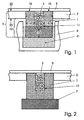
- the molded body 1 itself is porous in all of its wall areas, consisting of the side walls 14 and the bottom area 13, and has a central recess 11 into which a large number of sample particles 3 are introduced. If this molded body 1 is immersed in a vessel 4 filled with liquid by lowering the plate 2, a defined liquid filling of the molded body 1 takes place in a passive manner from below or via the lateral molded body walls 14.
- the porosity of the molded body 1 and the diameter distribution in the The recess 11 introduced into the particle packing is fixed in such a way that a liquid rise within the molded body is essentially caused by capillary forces.
- the molded body walls act as a filter with the appropriate porosity dimensions.
- Porous materials based on plastics are preferably used for the molded body 1. Such substances are produced by a sintering process at approx. 150 ° C. from granules based on polyethylene, polypropylene or polytetrafluoroethylene. However, porous glass or silicon, ceramics or metal frits can also be used.
- the amount of liquid absorbed is determined by the total pore volume of the molded body.
- the filling process is highly reproducible; a container formed by the molded body always holds the same amount of liquid.
- the interior of the recess 11 is homogeneously filled with sample particles 3.
- the diameters of the particles are set larger than the pores of the walls 14 and of the base 13. Due to the loose bed and the close packing of the particles, capillary forces also act within the reaction vessel when liquid is supplied.
- the recess 11 With a suitable volume ratio between the recess 3 holding the particles 3 of the molded body 1 and its porous walls, the latter preferably being given a larger volume and being in particular in the order of magnitude of 0.1-100 .mu.l, the recess 11 is in the Liquid intake filled up to their upper rim 15 well-defined.
- the embedded particles 3 are not only completely wetted, but are also converted in the case of oversupply of liquid reagent with a precisely determinable volume, which considerably simplifies the control of reaction procedures compared to the prior art.
- the reaction processes can be easily controlled since the amount of reagent in solution can be measured precisely.
- the aliquoting or dimensioning of the amount of liquid is defined by the volume of the porous molded body 1 and does not require any pipetting technique which inevitably brings about fluctuations when the filling process is repeated.
- the variability between the individual shaped bodies, which has a direct impact on the volume to be absorbed, is low, since the geometric deviations are minimal due to precise, precision-mechanical manufacture of the shaped bodies, are subject to prior quality control and cannot change from filling step to filling step.
- the microreaction vessels formed by the shaped body 1, which are in the Example a height h of 3.1 mm and an outer diameter of 1.75 mm have the recess 11 which is open towards the top on to make the introduction of the sample particles in bulk easier Way to ensure by filling up.
- a cover 8 formed by a film, in particular a self-adhesive film, closable are, in particular, by a cover 8 formed by a film, in particular a self-adhesive film, closable.
- a cover 8 formed by a film, in particular a self-adhesive film, closable.
- Self-filling from below is still completely covered by the Total reactor volume. This is the case with the state of the art usual reaction vessels with solid walls, such as Capillaries or tubes, impossible because air bubbles rise up the Prevent liquid.
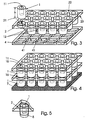
- Figure 3 shows a perspective view of part of a transparent shown plate 2 with several introduced moldings 1. Die Introduction of the molded body 1 in the recesses 21 and their In this example, the arrangement is such that their positioning corresponds to the distribution of cavities 41 from one of vessels 4 existing microtiter plate. Reactor carrier with such a passive Fillable moldings 1 can be more complex without use Automation technology directly onto the liquid-filled vessels 4 Microtiter plate can be placed. The liquids from the in the The multitude of samples presented to the microtiter plate then rise simultaneously the molded body 1 serving as a reaction container and wet it there held particles 3, with exactly one reaction vessel being a liquid from a cavity. The outside diameter of the Particle containers are chosen to be smaller than the inside diameter of the Cavities, so that the molded body 1, within which the desired Reaction should take place into which cavities can be inserted and contact the liquids inside.
- porous structures 7 which are complementary in shape to the bottom region of the shaped bodies, and are soaked in liquid or passed on.
- FIG. 2 given otherwise the same conditions as in FIG. 1, such a structure 7, which is assigned to only one molded body, is indicated;
- This structure is shown in FIG. 4 as a structure 7 which is continuous and covers all the shaped-body floor regions.
- the accuracy of fit in the contact area guarantees in each case the formation of the structure 7 an effective liquid transfer by capillary forces.
- Filter papers or structured porous plastics, glasses or ceramics can be used for such a liquid-transmitting structure.
- a plurality of identically designed plates 2 can be stacked one above the other, the liquid transfer from the lower moldings into the moldings of the next level in turn being effected by capillary forces over the upper rim 15 of each molded body 1.
- This stacking of plates 2 is useful for highly parallel processes, such as are common in combinatorial chemistry, for example.
- the particular advantage of correspondingly microstructured porous structures 7 as a liquid dispenser is the possibility of combinatorial filling.
- areas of a plate 2 carrying the shaped bodies 1 as reaction containers are wetted simultaneously or in succession with different liquid samples.
- the use of suitably cut or structured liquid dispensers creates the transition area that enables self-filling only in the areas provided for this purpose.
- reaction vessels can alternately be wetted in a row and column pattern with 96 different liquids each.
- This "orthogonal" liquid distribution is used in combinatorial chemistry, for example, for the synthesis of substance libraries.
- FIG. 5 is one further possibility of introducing a molded body into the plate 2 in a partial section shown, in which in the recess 21 of the plate 2nd first a sleeve 5 is introduced, which in turn is one Shaped body 1 so that only over the bottom area of the Shaped body a fluid supply is guaranteed.
Landscapes
- Chemical & Material Sciences (AREA)
- Chemical Kinetics & Catalysis (AREA)
- Organic Chemistry (AREA)
- Health & Medical Sciences (AREA)
- General Health & Medical Sciences (AREA)
- Clinical Laboratory Science (AREA)
- Hematology (AREA)
- Analytical Chemistry (AREA)
- Automatic Analysis And Handling Materials Therefor (AREA)
- Physical Or Chemical Processes And Apparatus (AREA)
- Sampling And Sample Adjustment (AREA)
- Investigating Or Analyzing Non-Biological Materials By The Use Of Chemical Means (AREA)
- Apparatus Associated With Microorganisms And Enzymes (AREA)
Claims (12)
- Support de réacteur comprenant plusieurs compartiments ouverts sur un côté, pouvant être fermé au moyen d'un couvercle et chargé de micro-échantillons, permettant d'y placer une multitude d'échantillons sous forme de particules de microcorps en vrac et ruisselants, les compartiments à micro-échantillons étant conçus de sorte qu'ils soient au raz de la surface du support, que, sur le côté fermé, ils dépassent le support et qu'ils présentent une ouverture au sol permettant le transfert de fluides, est caractérisé en ce qu'un plateau (2) est doté d'orifices (21) dans lesquels sont placés des corps aux formes déterminées (1) et aux parois poreuses (13, 14) permettant le passage et la montée du fluide dans le corps (1), dans l'essentiel par moyen des forces capillaires, le diamètre moyen des particules-échantillons (3) étant supérieur au diamètre des pores du corps à forme déterminée (1), mais d'autre part étant encore suffisamment petit pour que la montée du fluide, à travers les particules versées dans les compartiments, dans l'évidement (11) du corps à forme déterminée (1) , s'obtienne également dans l'essentiel par l'intervention des forces capillaires, la surface du corps à forme déterminée(1), sur le côté de l'évidement ouvert (11) se situant précisément soit au raz d'une première surface (22) du plateau (2) soit un peu en recul de sorte qu'au moins la partie (12) dépassant la deuxième surface (23) du plateau (2) puissent entrer en contact, au moins au sol, avec les agents fluides amenés (4, 41; 7; 15).
- Support suivant la revendication 1 est caractérisé en ce que la grandeur de la partie (12) du corps à forme déterminée (1), dépassant la deuxième surface (23) du plateau (2), est au moins égale à la moitié de la hauteur totale (h) du corps de forme déterminée.
- Support suivant la revendication 1 ou 2 est caractérisé en ce que le remplissage d'un fluide des corps aux formes déterminées (1) se fait uniquement par le sol (13) et/ou par les parois latérales (14) des corps aux formes déterminées (1).
- Support selon une des revendications 1 à 3 est caractérisé en ce que les orifices de passage (21) et, par conséquent, les corps aux formes déterminées (1) sont disposés sur le plateau (2) de sorte qu'ils se trouvent en face des cavités (41) d'un récipient contenant le fluide, par ex. d'une micro-plaque de titrage.
- Support suivant la revendication 1 est caractérisé en ce que la matière première utilisée pour la fabrication des corps aux formes déterminées (1) est soit un granulat de verre ou de matière plastique vitrifiée soit un verre mousse ou un silicium poreux ou une céramique ou une fritte métallique aux porosités allant de 5 à 75%.
- Support selon les revendication 1 à 5 est caractérisé en ce que le volume du corps à forme determinée (1) entre les parois latérales (14) et du sol (13) est plus grand que celui de l'évidement appliqué (11) et donc supérieur au volume total des particules introduites dans l'évidement (3).
- Support selon la revendication 6 est caractérisé en ce que le rapport entre le volume des parois poreuses du corps à forme déterminée et le volume de l'évidement (11) est égal au rapports allant de 1000 : 1 jusqu'à 1 : 1.
- Support selon les revendications 1 à 7 est caractérisé en ce que les parois latérales (14) des corps aux formes déterminées (1) sont entourées d'une enceinte imperméable.
- Support suivant la revendication 8 est caractérisé en ce que l'enceinte imperméable est formée par une douille (5) introduite dans l'évidement (21) du plateau (2).
- Support selon une des revendications 1 à 9 est caractérisé en ce que le couvercle (8) recouvre plusieurs corps aux formes déterminées (1) disposés en série.
- Support selon une des revendications 1 à 9 est caractérisé en ce que le couvercle (8) recouvre tous les corps aux formes déterminées (1) disposés sur le plateau (2).
- Support selon la revendication 10 ou 11 est caractérisé en ce que le recouvrement (8) est assuré par une feuille plastique dont une surface est autocollante.
Applications Claiming Priority (3)
| Application Number | Priority Date | Filing Date | Title |
|---|---|---|---|
| DE19825909 | 1998-06-10 | ||
| DE19825909A DE19825909C1 (de) | 1998-06-10 | 1998-06-10 | Reaktorträger mit mehreren Mikroprobenaufnahmekammern |
| PCT/EP1999/003694 WO1999064158A1 (fr) | 1998-06-10 | 1999-05-20 | Support de reacteur a plusieurs chambres de reception de microechantillons |
Publications (2)
| Publication Number | Publication Date |
|---|---|
| EP1083992A1 EP1083992A1 (fr) | 2001-03-21 |
| EP1083992B1 true EP1083992B1 (fr) | 2003-04-23 |
Family
ID=7870506
Family Applications (1)
| Application Number | Title | Priority Date | Filing Date |
|---|---|---|---|
| EP99927783A Expired - Lifetime EP1083992B1 (fr) | 1998-06-10 | 1999-05-20 | Support de reacteur a plusieurs chambres de reception de microechantillons |
Country Status (6)
| Country | Link |
|---|---|
| US (1) | US20010002984A1 (fr) |
| EP (1) | EP1083992B1 (fr) |
| AT (1) | ATE238101T1 (fr) |
| AU (1) | AU4501899A (fr) |
| DE (1) | DE19825909C1 (fr) |
| WO (1) | WO1999064158A1 (fr) |
Families Citing this family (24)
| Publication number | Priority date | Publication date | Assignee | Title |
|---|---|---|---|---|
| US6528324B1 (en) * | 1996-03-22 | 2003-03-04 | Ontogen Corporation | Apparatus for pre-determined mass sorting of positional-encoded solid phase synthesis supports |
| US7115231B1 (en) | 1998-06-09 | 2006-10-03 | Symyx Technologies, Inc. | Parallel reactor with knife-edge seal |
| US6770482B1 (en) * | 1999-07-16 | 2004-08-03 | General Electric | Method and apparatus for rapid screening of multiphase reactions |
| US6572828B1 (en) | 1999-07-16 | 2003-06-03 | General Electric Company | Method and apparatus for high-throughput chemical screening |
| AU2001236597A1 (en) * | 2000-01-31 | 2001-08-07 | Board Of Regents, The University Of Texas System | System and method for the analysis of bodily fluids |
| JP4471648B2 (ja) * | 2001-05-30 | 2010-06-02 | バイオレックス・セラピューティクス インコーポレイテッド | 高スループットスクリーニングのためのプレートおよび方法 |
| EP1281966A3 (fr) * | 2001-07-30 | 2003-06-18 | Fuji Photo Film Co., Ltd. | Méthode et appareil pour mettre en oeuvre une réaction entre un récepteur et un ligand |
| DE10218278B4 (de) * | 2002-04-19 | 2005-12-01 | Fraunhofer-Gesellschaft zur Förderung der angewandten Forschung e.V. | Mikroreaktor |
| EP1502097A2 (fr) * | 2002-04-26 | 2005-02-02 | Board of Regents, The University of Texas System | Methode et systeme permettant de detecter des facteurs de risque cardiaque |
| WO2004104922A2 (fr) | 2003-05-16 | 2004-12-02 | Board Of Regents, The University Of Texas System | Technologie de reconnaissance d'une image et d'une partie d'image |
| FR2858569B1 (fr) * | 2003-08-06 | 2005-11-04 | Jean Francois Siraudeau | Dispositif de diffusion d'un produit liquide dans une phase solide et procede associe |
| US7651868B2 (en) * | 2003-12-11 | 2010-01-26 | The Board Of Regents Of The University Of Texas System | Method and system for the analysis of saliva using a sensor array |
| US8105849B2 (en) | 2004-02-27 | 2012-01-31 | Board Of Regents, The University Of Texas System | Integration of fluids and reagents into self-contained cartridges containing sensor elements |
| US8101431B2 (en) | 2004-02-27 | 2012-01-24 | Board Of Regents, The University Of Texas System | Integration of fluids and reagents into self-contained cartridges containing sensor elements and reagent delivery systems |
| DE102005014691B4 (de) * | 2005-03-29 | 2010-08-19 | Sartorius Stedim Biotech Gmbh | Mikroarray-Vorrichtung und Verfahren zum Präparieren eines Probenträgers |
| EP1910824A4 (fr) | 2005-05-31 | 2012-11-21 | Labnow Inc | Méthodes et compositions en rapport avec la détermination et l utilisation de la numération de globules blancs |
| CA2613078A1 (fr) * | 2005-06-24 | 2007-01-04 | Board Of Regents, The University Of Texas System | Systemes et procedes faisant appel a des cartouches autonomes comprenant des systemes de detection et des systemes de distribution de fluides |
| GB0913258D0 (en) * | 2009-07-29 | 2009-09-02 | Dynex Technologies Inc | Reagent dispenser |
| US8697005B2 (en) * | 2010-08-02 | 2014-04-15 | Pierre F. Indermuhle | Assemblies for multiplex assays |
| DE102011106498B4 (de) | 2011-06-15 | 2016-08-04 | Heraeus Noblelight Gmbh | Bestrahlungsmodul für Mikrophotoreaktoren |
| KR20150009982A (ko) | 2012-05-03 | 2015-01-27 | 쇼오트 아게 | 의료, 제약 또는 화장품 어플리케이션들을 위한 물질들을 저장하기 위한 컨테이너들을 처리하기 위한 방법 및 장치 |
| KR101655726B1 (ko) | 2012-05-03 | 2016-09-07 | 쇼오트 아게 | 의료, 제약 또는 화장품 어플리케이션들을 위한 물질들을 저장하기 위한 컨테이너들을 처리하기 위한 방법 및 장치 |
| DE102013111600B4 (de) | 2013-10-21 | 2018-04-05 | Schott Ag | Haltestruktur zum Halten von Behältern für Substanzen für medizinische, pharmazeutische oder kosmetische Anwendungen, sowie Transport- und Verpackungsbehälter mit selbiger |
| CN105251552A (zh) * | 2015-11-17 | 2016-01-20 | 长沙开元仪器股份有限公司 | 一种壁挂式煤样存查样库 |
Family Cites Families (27)
| Publication number | Priority date | Publication date | Assignee | Title |
|---|---|---|---|---|
| US4483925A (en) * | 1982-12-30 | 1984-11-20 | Becton, Dickinson And Company | Liquid removal device |
| DE3336738A1 (de) * | 1983-10-08 | 1985-05-02 | Wolfgang Dr. 7400 Tübingen Heizmann | Titerplatte |
| US4828386A (en) * | 1987-06-19 | 1989-05-09 | Pall Corporation | Multiwell plates containing membrane inserts |
| DE8717464U1 (fr) * | 1987-07-11 | 1988-12-29 | Boehringer Ingelheim Kg, 6507 Ingelheim, De | |
| US4889613A (en) * | 1987-09-11 | 1989-12-26 | Beckman Instruments, Inc. | Analytical apparatus, electrode and sample container for use therewith |
| US5011779A (en) * | 1988-01-21 | 1991-04-30 | Long Island Jewish Medical Center | Apparatus for rapid deposition of test samples on an absorbent support |
| US5159197A (en) * | 1988-02-16 | 1992-10-27 | Difco Laboratories | Luminescence test and exposure apparatus |
| US4985631A (en) * | 1988-02-16 | 1991-01-15 | Wannlund Jon C | Luminescence exposure apparatus |
| US5035866A (en) * | 1988-02-16 | 1991-07-30 | Wannlund Jon C | Luminescence reaction test apparatus |
| US5096676A (en) * | 1989-01-27 | 1992-03-17 | Mcpherson Alexander | Crystal growing apparatus |
| US5437979A (en) * | 1989-07-24 | 1995-08-01 | Beckman Instruments, Inc. | Solid phase system for sequential reactions |
| DE9100320U1 (fr) * | 1991-01-09 | 1991-04-25 | Behm, Erasmus, Dr.Sc.Med., O-2540 Rostock, De | |
| US5417923A (en) * | 1991-04-24 | 1995-05-23 | Pfizer Inc. | Assay tray assembly |
| US5650323A (en) * | 1991-06-26 | 1997-07-22 | Costar Corporation | System for growing and manipulating tissue cultures using 96-well format equipment |
| US5626914A (en) * | 1992-09-17 | 1997-05-06 | Coors Ceramics Company | Ceramic-metal composites |
| US5525374A (en) * | 1992-09-17 | 1996-06-11 | Golden Technologies Company | Method for making ceramic-metal gradient composites |
| US5676907A (en) * | 1992-09-17 | 1997-10-14 | Coors Ceramics Company | Method for making near net shape ceramic-metal composites |
| GB9311276D0 (en) * | 1993-06-01 | 1993-07-21 | Whatman Scient Limited | Well inserts for use in tissue culture |
| EP1157743B1 (fr) * | 1993-10-28 | 2009-03-11 | Houston Advanced Research Center | Dispositif à microstructure poreuse assurant un écoulement permettant la détection des réactions de liaison |
| DE4432326C2 (de) * | 1994-09-10 | 1997-07-17 | Fritz Nerbe Nachfolger Juergen | Verfahren zur toxikologischen Prüfung von Werkstoffen, insbesondere Kunststoffen, und Vorrichtung zur Durchführung des Verfahrens |
| US5674395A (en) * | 1995-06-05 | 1997-10-07 | Millipore Corporation | Multiple sample separator |
| US5587321A (en) * | 1995-07-31 | 1996-12-24 | University Of Kansas | Moated tissue culture plate |
| GB9603945D0 (en) * | 1996-02-24 | 1996-04-24 | Univ Dundee | A microreactor |
| US6599714B1 (en) * | 1996-03-13 | 2003-07-29 | University Technologies International Inc. | Method of growing and analyzing a biofilm |
| CA2263851A1 (fr) * | 1996-08-21 | 1998-02-26 | Damien Dunnington | Procede rapide d'amenagement de banques combinatoires a base de billes |
| US6083761A (en) * | 1996-12-02 | 2000-07-04 | Glaxo Wellcome Inc. | Method and apparatus for transferring and combining reagents |
| US5965092A (en) * | 1997-10-15 | 1999-10-12 | Eastman Kodak Company | Integrated micro-ceramic chemical plant with insertable micro-filters |
-
1998
- 1998-06-10 DE DE19825909A patent/DE19825909C1/de not_active Expired - Fee Related
-
1999
- 1999-05-20 AU AU45018/99A patent/AU4501899A/en not_active Abandoned
- 1999-05-20 AT AT99927783T patent/ATE238101T1/de not_active IP Right Cessation
- 1999-05-20 EP EP99927783A patent/EP1083992B1/fr not_active Expired - Lifetime
- 1999-05-20 WO PCT/EP1999/003694 patent/WO1999064158A1/fr active IP Right Grant
-
2000
- 2000-12-11 US US09/735,724 patent/US20010002984A1/en not_active Abandoned
Also Published As
| Publication number | Publication date |
|---|---|
| DE19825909C1 (de) | 1999-11-25 |
| ATE238101T1 (de) | 2003-05-15 |
| EP1083992A1 (fr) | 2001-03-21 |
| US20010002984A1 (en) | 2001-06-07 |
| WO1999064158A1 (fr) | 1999-12-16 |
| AU4501899A (en) | 1999-12-30 |
Similar Documents
| Publication | Publication Date | Title |
|---|---|---|
| EP1083992B1 (fr) | Support de reacteur a plusieurs chambres de reception de microechantillons | |
| DE60211155T2 (de) | Mehrfachlochtestvorrichtung | |
| DE60216076T2 (de) | Hohlfasermembran probenpräparationsanordnungen | |
| DE69831956T2 (de) | Mikrotiterplatte. | |
| EP1110609B1 (fr) | Système de traitement d'échantillons dans un dispositif à compartiments multiples | |
| EP1718409B1 (fr) | Dispositif utilise pour effectuer des analyses microscopiques de fluides | |
| EP2205716B1 (fr) | Microréacteur | |
| EP1160573A2 (fr) | Plaque de microtitrage et dispositif de pipetage multivoies couplé à celui | |
| WO2002003058A2 (fr) | Dispositif et procede pour mettre en contact electrique des cellules biologiques en suspension dans un liquide | |
| WO2001026797A2 (fr) | Traitement d'echantillons dans des solutions presentant une faible surface de contact de paroi definie | |
| EP2192984A2 (fr) | Système microfluidique partiellement actif pour la culture cellulaire en 3d et procédé pour sa perfusion | |
| EP1128902B1 (fr) | Dispositif permettant de trier des echantillons, de transferer et de collecter des microperles et procede permettant de faire fonctionner ledit dispositif | |
| EP1222028B1 (fr) | Plaque de support destinee a recevoir de maniere ordonnee des particules d'echantillon | |
| WO1998016312A1 (fr) | Pipette | |
| EP1379622B1 (fr) | Procede et dispositif de culture et/ou de repartition de particules | |
| EP1397201B2 (fr) | Recipient de reaction servant a produire des echantillons | |
| DE10117723A1 (de) | Probenträger, insbesondere für biochemische Reaktionen | |
| DE19652327C2 (de) | Verfahren und Vorrichtung zur Durchführung chemischer Reaktionsfolgen | |
| DE19906264C1 (de) | Verfahren und Vorrichtung für differenzspektroskopische Messungen | |
| DE102007041071B4 (de) | Vorrichtung zur Aufnahme einer Flüssigkeit sowie Vorrichtung zur Aufbringung von Flüssigkeiten auf Probenträger und Verfahren hierzu | |
| AT500167B1 (de) | Reaktionsgefäss | |
| WO2023110944A1 (fr) | Unité de cuve à réaction, et procédés de retrait sélectif d'un liquide contenu dans une cuve à réaction d'une unité de cuve à réaction, et d'introduction d'un liquide contenant une substance cible dans celle-ci | |
| DE102015006802B4 (de) | Übertrag im Musterformat von Wirkstoffbibliotheken in ein Muster aus flüssigen Kompartimenten | |
| DE10147513B4 (de) | Verfahren zur Minimierung der Verdunstung in Probenträgern | |
| DE102005036967A1 (de) | Vorrichtung zum parallelen Befüllen von Gefäßen |
Legal Events
| Date | Code | Title | Description |
|---|---|---|---|
| PUAI | Public reference made under article 153(3) epc to a published international application that has entered the european phase |
Free format text: ORIGINAL CODE: 0009012 |
|
| 17P | Request for examination filed |
Effective date: 20001215 |
|
| AK | Designated contracting states |
Kind code of ref document: A1 Designated state(s): AT BE CH CY DK ES FI FR GB GR IE IT LI LU MC NL PT SE |
|
| GRAG | Despatch of communication of intention to grant |
Free format text: ORIGINAL CODE: EPIDOS AGRA |
|
| 17Q | First examination report despatched |
Effective date: 20020612 |
|
| GRAG | Despatch of communication of intention to grant |
Free format text: ORIGINAL CODE: EPIDOS AGRA |
|
| GRAG | Despatch of communication of intention to grant |
Free format text: ORIGINAL CODE: EPIDOS AGRA |
|
| GRAH | Despatch of communication of intention to grant a patent |
Free format text: ORIGINAL CODE: EPIDOS IGRA |
|
| RIN1 | Information on inventor provided before grant (corrected) |
Inventor name: VETTER, DIRK |
|
| RAP1 | Party data changed (applicant data changed or rights of an application transferred) |
Owner name: GRAFFINITY PHARMACEUTICALS AKTIENGESELLSCHAFT |
|
| GRAH | Despatch of communication of intention to grant a patent |
Free format text: ORIGINAL CODE: EPIDOS IGRA |
|
| GRAA | (expected) grant |
Free format text: ORIGINAL CODE: 0009210 |
|
| AK | Designated contracting states |
Designated state(s): AT BE CH CY DK ES FI FR GB GR IE IT LI LU MC NL PT SE |
|
| PG25 | Lapsed in a contracting state [announced via postgrant information from national office to epo] |
Ref country code: NL Free format text: LAPSE BECAUSE OF FAILURE TO SUBMIT A TRANSLATION OF THE DESCRIPTION OR TO PAY THE FEE WITHIN THE PRESCRIBED TIME-LIMIT Effective date: 20030423 Ref country code: IT Free format text: LAPSE BECAUSE OF FAILURE TO SUBMIT A TRANSLATION OF THE DESCRIPTION OR TO PAY THE FEE WITHIN THE PRESCRIBED TIME-LIMIT;WARNING: LAPSES OF ITALIAN PATENTS WITH EFFECTIVE DATE BEFORE 2007 MAY HAVE OCCURRED AT ANY TIME BEFORE 2007. THE CORRECT EFFECTIVE DATE MAY BE DIFFERENT FROM THE ONE RECORDED. Effective date: 20030423 Ref country code: IE Free format text: LAPSE BECAUSE OF NON-PAYMENT OF DUE FEES Effective date: 20030423 Ref country code: FI Free format text: LAPSE BECAUSE OF FAILURE TO SUBMIT A TRANSLATION OF THE DESCRIPTION OR TO PAY THE FEE WITHIN THE PRESCRIBED TIME-LIMIT Effective date: 20030423 |
|
| REG | Reference to a national code |
Ref country code: GB Ref legal event code: FG4D Free format text: NOT ENGLISH |
|
| REG | Reference to a national code |
Ref country code: CH Ref legal event code: EP |
|
| PG25 | Lapsed in a contracting state [announced via postgrant information from national office to epo] |
Ref country code: CY Free format text: LAPSE BECAUSE OF FAILURE TO SUBMIT A TRANSLATION OF THE DESCRIPTION OR TO PAY THE FEE WITHIN THE PRESCRIBED TIME-LIMIT Effective date: 20030520 |
|
| REG | Reference to a national code |
Ref country code: IE Ref legal event code: FG4D Free format text: GERMAN |
|
| PG25 | Lapsed in a contracting state [announced via postgrant information from national office to epo] |
Ref country code: MC Free format text: LAPSE BECAUSE OF NON-PAYMENT OF DUE FEES Effective date: 20030531 |
|
| PG25 | Lapsed in a contracting state [announced via postgrant information from national office to epo] |
Ref country code: SE Free format text: LAPSE BECAUSE OF FAILURE TO SUBMIT A TRANSLATION OF THE DESCRIPTION OR TO PAY THE FEE WITHIN THE PRESCRIBED TIME-LIMIT Effective date: 20030723 Ref country code: PT Free format text: LAPSE BECAUSE OF FAILURE TO SUBMIT A TRANSLATION OF THE DESCRIPTION OR TO PAY THE FEE WITHIN THE PRESCRIBED TIME-LIMIT Effective date: 20030723 Ref country code: GR Free format text: LAPSE BECAUSE OF FAILURE TO SUBMIT A TRANSLATION OF THE DESCRIPTION OR TO PAY THE FEE WITHIN THE PRESCRIBED TIME-LIMIT Effective date: 20030723 Ref country code: DK Free format text: LAPSE BECAUSE OF FAILURE TO SUBMIT A TRANSLATION OF THE DESCRIPTION OR TO PAY THE FEE WITHIN THE PRESCRIBED TIME-LIMIT Effective date: 20030723 |
|
| GBT | Gb: translation of ep patent filed (gb section 77(6)(a)/1977) |
Effective date: 20030729 |
|
| NLV1 | Nl: lapsed or annulled due to failure to fulfill the requirements of art. 29p and 29m of the patents act | ||
| PG25 | Lapsed in a contracting state [announced via postgrant information from national office to epo] |
Ref country code: ES Free format text: LAPSE BECAUSE OF FAILURE TO SUBMIT A TRANSLATION OF THE DESCRIPTION OR TO PAY THE FEE WITHIN THE PRESCRIBED TIME-LIMIT Effective date: 20031030 |
|
| REG | Reference to a national code |
Ref country code: IE Ref legal event code: FD4D Ref document number: 1083992E Country of ref document: IE |
|
| ET | Fr: translation filed | ||
| PLBE | No opposition filed within time limit |
Free format text: ORIGINAL CODE: 0009261 |
|
| STAA | Information on the status of an ep patent application or granted ep patent |
Free format text: STATUS: NO OPPOSITION FILED WITHIN TIME LIMIT |
|
| PGFP | Annual fee paid to national office [announced via postgrant information from national office to epo] |
Ref country code: FR Payment date: 20040330 Year of fee payment: 6 Ref country code: CH Payment date: 20040330 Year of fee payment: 6 |
|
| PGFP | Annual fee paid to national office [announced via postgrant information from national office to epo] |
Ref country code: LU Payment date: 20040401 Year of fee payment: 6 |
|
| 26N | No opposition filed |
Effective date: 20040126 |
|
| PGFP | Annual fee paid to national office [announced via postgrant information from national office to epo] |
Ref country code: BE Payment date: 20040423 Year of fee payment: 6 |
|
| PGFP | Annual fee paid to national office [announced via postgrant information from national office to epo] |
Ref country code: AT Payment date: 20040510 Year of fee payment: 6 |
|
| PGFP | Annual fee paid to national office [announced via postgrant information from national office to epo] |
Ref country code: GB Payment date: 20040519 Year of fee payment: 6 |
|
| PG25 | Lapsed in a contracting state [announced via postgrant information from national office to epo] |
Ref country code: LU Free format text: LAPSE BECAUSE OF NON-PAYMENT OF DUE FEES Effective date: 20050520 Ref country code: GB Free format text: LAPSE BECAUSE OF NON-PAYMENT OF DUE FEES Effective date: 20050520 Ref country code: AT Free format text: LAPSE BECAUSE OF NON-PAYMENT OF DUE FEES Effective date: 20050520 |
|
| PG25 | Lapsed in a contracting state [announced via postgrant information from national office to epo] |
Ref country code: LI Free format text: LAPSE BECAUSE OF NON-PAYMENT OF DUE FEES Effective date: 20050531 Ref country code: CH Free format text: LAPSE BECAUSE OF NON-PAYMENT OF DUE FEES Effective date: 20050531 Ref country code: BE Free format text: LAPSE BECAUSE OF NON-PAYMENT OF DUE FEES Effective date: 20050531 |
|
| BERE | Be: lapsed |
Owner name: *GRAFFINITY PHARMACEUTICALS A.G. Effective date: 20050531 |
|
| REG | Reference to a national code |
Ref country code: CH Ref legal event code: PL |
|
| GBPC | Gb: european patent ceased through non-payment of renewal fee |
Effective date: 20050520 |
|
| PG25 | Lapsed in a contracting state [announced via postgrant information from national office to epo] |
Ref country code: FR Free format text: LAPSE BECAUSE OF NON-PAYMENT OF DUE FEES Effective date: 20060131 |
|
| REG | Reference to a national code |
Ref country code: FR Ref legal event code: ST Effective date: 20060131 |
|
| BERE | Be: lapsed |
Owner name: *GRAFFINITY PHARMACEUTICALS A.G. Effective date: 20050531 |