EP2205716B1 - Microréacteur - Google Patents
Microréacteur Download PDFInfo
- Publication number
- EP2205716B1 EP2205716B1 EP08837177.8A EP08837177A EP2205716B1 EP 2205716 B1 EP2205716 B1 EP 2205716B1 EP 08837177 A EP08837177 A EP 08837177A EP 2205716 B1 EP2205716 B1 EP 2205716B1
- Authority
- EP
- European Patent Office
- Prior art keywords
- microreactor
- cavity
- cover
- lid
- cross
- Prior art date
- Legal status (The legal status is an assumption and is not a legal conclusion. Google has not performed a legal analysis and makes no representation as to the accuracy of the status listed.)
- Active
Links
- 238000005259 measurement Methods 0.000 claims description 18
- 238000000034 method Methods 0.000 claims description 13
- 230000008569 process Effects 0.000 claims description 11
- 238000005070 sampling Methods 0.000 claims description 9
- 239000012780 transparent material Substances 0.000 claims description 2
- 239000003153 chemical reaction reagent Substances 0.000 claims 1
- 239000007788 liquid Substances 0.000 description 29
- 238000006243 chemical reaction Methods 0.000 description 25
- 238000012546 transfer Methods 0.000 description 23
- 239000007789 gas Substances 0.000 description 15
- QVGXLLKOCUKJST-UHFFFAOYSA-N atomic oxygen Chemical compound [O] QVGXLLKOCUKJST-UHFFFAOYSA-N 0.000 description 12
- 239000001301 oxygen Substances 0.000 description 12
- 229910052760 oxygen Inorganic materials 0.000 description 12
- 238000003491 array Methods 0.000 description 11
- 230000015572 biosynthetic process Effects 0.000 description 11
- 238000005755 formation reaction Methods 0.000 description 11
- 239000000463 material Substances 0.000 description 11
- 230000033001 locomotion Effects 0.000 description 9
- 239000012295 chemical reaction liquid Substances 0.000 description 8
- 238000010276 construction Methods 0.000 description 8
- 239000007787 solid Substances 0.000 description 8
- 239000000243 solution Substances 0.000 description 8
- 238000013459 approach Methods 0.000 description 7
- 230000003287 optical effect Effects 0.000 description 7
- 238000013461 design Methods 0.000 description 6
- 238000002156 mixing Methods 0.000 description 6
- 239000012071 phase Substances 0.000 description 6
- 230000008020 evaporation Effects 0.000 description 5
- 238000001704 evaporation Methods 0.000 description 5
- 239000000523 sample Substances 0.000 description 5
- 239000000443 aerosol Substances 0.000 description 4
- 230000008901 benefit Effects 0.000 description 4
- 238000002474 experimental method Methods 0.000 description 4
- 238000000855 fermentation Methods 0.000 description 4
- 230000004151 fermentation Effects 0.000 description 4
- 239000012528 membrane Substances 0.000 description 4
- 239000011541 reaction mixture Substances 0.000 description 4
- 230000009467 reduction Effects 0.000 description 4
- 238000007789 sealing Methods 0.000 description 4
- 239000000126 substance Substances 0.000 description 4
- 230000007704 transition Effects 0.000 description 4
- 230000002210 biocatalytic effect Effects 0.000 description 3
- 210000004027 cell Anatomy 0.000 description 3
- 230000008021 deposition Effects 0.000 description 3
- 239000012530 fluid Substances 0.000 description 3
- 239000011888 foil Substances 0.000 description 3
- 239000007791 liquid phase Substances 0.000 description 3
- 229920003023 plastic Polymers 0.000 description 3
- 239000002689 soil Substances 0.000 description 3
- 239000000725 suspension Substances 0.000 description 3
- 238000012360 testing method Methods 0.000 description 3
- 239000002028 Biomass Substances 0.000 description 2
- 230000009286 beneficial effect Effects 0.000 description 2
- 238000005842 biochemical reaction Methods 0.000 description 2
- 238000004113 cell culture Methods 0.000 description 2
- 238000012512 characterization method Methods 0.000 description 2
- 238000011109 contamination Methods 0.000 description 2
- 238000011161 development Methods 0.000 description 2
- 239000003814 drug Substances 0.000 description 2
- 230000000694 effects Effects 0.000 description 2
- 238000005187 foaming Methods 0.000 description 2
- 238000007373 indentation Methods 0.000 description 2
- 230000007246 mechanism Effects 0.000 description 2
- 230000000813 microbial effect Effects 0.000 description 2
- 238000009629 microbiological culture Methods 0.000 description 2
- 229920001296 polysiloxane Polymers 0.000 description 2
- 230000008092 positive effect Effects 0.000 description 2
- 239000000376 reactant Substances 0.000 description 2
- 239000000758 substrate Substances 0.000 description 2
- 241000196324 Embryophyta Species 0.000 description 1
- 102000004190 Enzymes Human genes 0.000 description 1
- 108090000790 Enzymes Proteins 0.000 description 1
- 241000427213 Plukenetia conophora Species 0.000 description 1
- 206010053648 Vascular occlusion Diseases 0.000 description 1
- 239000002313 adhesive film Substances 0.000 description 1
- 238000004458 analytical method Methods 0.000 description 1
- 210000004102 animal cell Anatomy 0.000 description 1
- 238000010923 batch production Methods 0.000 description 1
- 239000000872 buffer Substances 0.000 description 1
- 230000001413 cellular effect Effects 0.000 description 1
- 238000001311 chemical methods and process Methods 0.000 description 1
- 230000000295 complement effect Effects 0.000 description 1
- 230000005574 cross-species transmission Effects 0.000 description 1
- 238000012258 culturing Methods 0.000 description 1
- 238000001514 detection method Methods 0.000 description 1
- 238000007599 discharging Methods 0.000 description 1
- 238000005516 engineering process Methods 0.000 description 1
- 238000006911 enzymatic reaction Methods 0.000 description 1
- 229920002457 flexible plastic Polymers 0.000 description 1
- 229920005570 flexible polymer Polymers 0.000 description 1
- GNBHRKFJIUUOQI-UHFFFAOYSA-N fluorescein Chemical compound O1C(=O)C2=CC=CC=C2C21C1=CC=C(O)C=C1OC1=CC(O)=CC=C21 GNBHRKFJIUUOQI-UHFFFAOYSA-N 0.000 description 1
- 239000001963 growth medium Substances 0.000 description 1
- 210000005260 human cell Anatomy 0.000 description 1
- 238000001746 injection moulding Methods 0.000 description 1
- 239000006194 liquid suspension Substances 0.000 description 1
- 238000000691 measurement method Methods 0.000 description 1
- 238000010327 methods by industry Methods 0.000 description 1
- 244000005700 microbiome Species 0.000 description 1
- 239000000203 mixture Substances 0.000 description 1
- 238000012986 modification Methods 0.000 description 1
- 230000004048 modification Effects 0.000 description 1
- 238000012544 monitoring process Methods 0.000 description 1
- 229920000642 polymer Polymers 0.000 description 1
- 239000011148 porous material Substances 0.000 description 1
- 238000003825 pressing Methods 0.000 description 1
- 230000002265 prevention Effects 0.000 description 1
- 230000002441 reversible effect Effects 0.000 description 1
- 238000012216 screening Methods 0.000 description 1
- 238000007423 screening assay Methods 0.000 description 1
- 239000007858 starting material Substances 0.000 description 1
- 238000009827 uniform distribution Methods 0.000 description 1
- 238000009736 wetting Methods 0.000 description 1
Images


Classifications
-
- C—CHEMISTRY; METALLURGY
- C12—BIOCHEMISTRY; BEER; SPIRITS; WINE; VINEGAR; MICROBIOLOGY; ENZYMOLOGY; MUTATION OR GENETIC ENGINEERING
- C12M—APPARATUS FOR ENZYMOLOGY OR MICROBIOLOGY; APPARATUS FOR CULTURING MICROORGANISMS FOR PRODUCING BIOMASS, FOR GROWING CELLS OR FOR OBTAINING FERMENTATION OR METABOLIC PRODUCTS, i.e. BIOREACTORS OR FERMENTERS
- C12M23/00—Constructional details, e.g. recesses, hinges
- C12M23/38—Caps; Covers; Plugs; Pouring means
-
- B—PERFORMING OPERATIONS; TRANSPORTING
- B01—PHYSICAL OR CHEMICAL PROCESSES OR APPARATUS IN GENERAL
- B01F—MIXING, e.g. DISSOLVING, EMULSIFYING OR DISPERSING
- B01F31/00—Mixers with shaking, oscillating, or vibrating mechanisms
- B01F31/20—Mixing the contents of independent containers, e.g. test tubes
- B01F31/22—Mixing the contents of independent containers, e.g. test tubes with supporting means moving in a horizontal plane, e.g. describing an orbital path for moving the containers about an axis which intersects the receptacle axis at an angle
-
- B—PERFORMING OPERATIONS; TRANSPORTING
- B01—PHYSICAL OR CHEMICAL PROCESSES OR APPARATUS IN GENERAL
- B01F—MIXING, e.g. DISSOLVING, EMULSIFYING OR DISPERSING
- B01F35/00—Accessories for mixers; Auxiliary operations or auxiliary devices; Parts or details of general application
- B01F35/50—Mixing receptacles
- B01F35/53—Mixing receptacles characterised by the configuration of the interior, e.g. baffles for facilitating the mixing of components
-
- B—PERFORMING OPERATIONS; TRANSPORTING
- B01—PHYSICAL OR CHEMICAL PROCESSES OR APPARATUS IN GENERAL
- B01L—CHEMICAL OR PHYSICAL LABORATORY APPARATUS FOR GENERAL USE
- B01L3/00—Containers or dishes for laboratory use, e.g. laboratory glassware; Droppers
- B01L3/50—Containers for the purpose of retaining a material to be analysed, e.g. test tubes
- B01L3/508—Containers for the purpose of retaining a material to be analysed, e.g. test tubes rigid containers not provided for above
- B01L3/5085—Containers for the purpose of retaining a material to be analysed, e.g. test tubes rigid containers not provided for above for multiple samples, e.g. microtitration plates
-
- C—CHEMISTRY; METALLURGY
- C12—BIOCHEMISTRY; BEER; SPIRITS; WINE; VINEGAR; MICROBIOLOGY; ENZYMOLOGY; MUTATION OR GENETIC ENGINEERING
- C12M—APPARATUS FOR ENZYMOLOGY OR MICROBIOLOGY; APPARATUS FOR CULTURING MICROORGANISMS FOR PRODUCING BIOMASS, FOR GROWING CELLS OR FOR OBTAINING FERMENTATION OR METABOLIC PRODUCTS, i.e. BIOREACTORS OR FERMENTERS
- C12M23/00—Constructional details, e.g. recesses, hinges
- C12M23/02—Form or structure of the vessel
- C12M23/12—Well or multiwell plates
-
- C—CHEMISTRY; METALLURGY
- C12—BIOCHEMISTRY; BEER; SPIRITS; WINE; VINEGAR; MICROBIOLOGY; ENZYMOLOGY; MUTATION OR GENETIC ENGINEERING
- C12M—APPARATUS FOR ENZYMOLOGY OR MICROBIOLOGY; APPARATUS FOR CULTURING MICROORGANISMS FOR PRODUCING BIOMASS, FOR GROWING CELLS OR FOR OBTAINING FERMENTATION OR METABOLIC PRODUCTS, i.e. BIOREACTORS OR FERMENTERS
- C12M23/00—Constructional details, e.g. recesses, hinges
- C12M23/24—Gas permeable parts
-
- B—PERFORMING OPERATIONS; TRANSPORTING
- B01—PHYSICAL OR CHEMICAL PROCESSES OR APPARATUS IN GENERAL
- B01J—CHEMICAL OR PHYSICAL PROCESSES, e.g. CATALYSIS OR COLLOID CHEMISTRY; THEIR RELEVANT APPARATUS
- B01J2219/00—Chemical, physical or physico-chemical processes in general; Their relevant apparatus
- B01J2219/00274—Sequential or parallel reactions; Apparatus and devices for combinatorial chemistry or for making arrays; Chemical library technology
- B01J2219/00277—Apparatus
- B01J2219/00279—Features relating to reactor vessels
- B01J2219/00306—Reactor vessels in a multiple arrangement
- B01J2219/00313—Reactor vessels in a multiple arrangement the reactor vessels being formed by arrays of wells in blocks
- B01J2219/00315—Microtiter plates
-
- B—PERFORMING OPERATIONS; TRANSPORTING
- B01—PHYSICAL OR CHEMICAL PROCESSES OR APPARATUS IN GENERAL
- B01J—CHEMICAL OR PHYSICAL PROCESSES, e.g. CATALYSIS OR COLLOID CHEMISTRY; THEIR RELEVANT APPARATUS
- B01J2219/00—Chemical, physical or physico-chemical processes in general; Their relevant apparatus
- B01J2219/00274—Sequential or parallel reactions; Apparatus and devices for combinatorial chemistry or for making arrays; Chemical library technology
- B01J2219/00277—Apparatus
- B01J2219/00479—Means for mixing reactants or products in the reaction vessels
-
- B—PERFORMING OPERATIONS; TRANSPORTING
- B01—PHYSICAL OR CHEMICAL PROCESSES OR APPARATUS IN GENERAL
- B01L—CHEMICAL OR PHYSICAL LABORATORY APPARATUS FOR GENERAL USE
- B01L2300/00—Additional constructional details
- B01L2300/08—Geometry, shape and general structure
- B01L2300/0809—Geometry, shape and general structure rectangular shaped
- B01L2300/0829—Multi-well plates; Microtitration plates
-
- B—PERFORMING OPERATIONS; TRANSPORTING
- B01—PHYSICAL OR CHEMICAL PROCESSES OR APPARATUS IN GENERAL
- B01L—CHEMICAL OR PHYSICAL LABORATORY APPARATUS FOR GENERAL USE
- B01L2300/00—Additional constructional details
- B01L2300/08—Geometry, shape and general structure
- B01L2300/0848—Specific forms of parts of containers
- B01L2300/0858—Side walls
Definitions
- the invention relates to a microreactor having at least one cavity, which has a bottom, a side wall and an opening opposite the bottom, wherein a parallel to the bottom of the side wall intersecting cross-section has a different shape from a round, square or rectangular shape.
- microreactor arrays e.g. 6, 24, 48, 96, 384 or more individual microreactors realize.
- volume of the individual reactors may also be different. While it is spoken at scales below 10 ml of microreactors, a further reduction of the volume to less than 1 ml, less than 500 ul, less than 100 ul or even less than 10 ul take place.
- a microreactor serves as a reaction vessel for biochemical, chemical or enzymatic reactions as well as microbial fermentations.
- a reactor array allows the study of cell cultures in high parallelism with low work volume, high information gain and the possibility for simplified automation. Such arrays are particularly useful for automating screening assays with improved mixing and mass transfer conditions, and allow for externally isolated or sterile, aseptic or monoseptic operation.
- Important criteria for suitable operating conditions are two criteria: the possibility of carrying out the corresponding tests under sterile or monoseptic conditions and ensuring a sufficient and sufficient transfer of the biological or biocatalytic reaction system (liquid-liquid, liquid-gas, solid). liquid, solid-gas).
- Microreactor arrays such as microtiter plates, provide an ideal platform for achieving a high level of parallelization. Owing to the small reaction volumes (eg> 10 ⁇ l to ⁇ 10 ml per chamber), the high degree of parallelization (eg 6 to 1536 chambers per plate) and the possibility of automating the cultivation processes (robot-manageable form), microreactor arrays are the most cost-effective and cost-effective most promising bioreactor.
- microtiter plates are already being used to screen biological systems.
- the individual reaction chambers are filled, inoculated and incubated on a rotary shaker. By the most orbital shaking the entry of oxygen is improved in the reaction liquids and achieved a thorough mixing of the reaction mixture.
- the microtiter plates are covered by an air-permeable membrane (pore size ⁇ 0.2 ⁇ m) or an airtight foil or lid construction, or cultured open in a sterile environment.
- microtiter plates used for the applications described are today offered by various manufacturers in two basic versions: with circular or with rectangular cavities.
- the first microtiter plates were made in 1951 by Dr. med. G. Takatsky made and possessed a round cross-section.
- microtiter plates of square and rectangular cross-section were introduced.
- microtiter plates are used in many fields of chemistry, medicine, biotechnology and biology, so that almost no development has taken place specifically for the cultivation of cells.
- baffles can contribute to severe dripping / splashing, resulting in inhomogeneities, increased wall growth and wetting and occlusion of the gas permeable cover of the plates ( Büchs J., Introduction to the Problems and Problems of Shake Cultures, Biochem. Closely. J. 7 (2), 91-98, 2001 ). Furthermore, there is no further indication on the market and in the specialist literature for the realization and examination of a microtiter plate with a variation of the cavity geometry (outside of the circular and the rectangular cross-section).
- microtiter plates To cover such microtiter plates different systems are on the market. Firstly, most manufacturers of microtiter plates include a plastic lid that is loosely placed on the microtiter plate.
- mats made of flexible plastic are sold, whose knob-like protuberances engage in each individual cavity and thus close it.
- Another microtiter plate is from the EP 1 733 793 A2 known.
- the object of the invention is to overcome the above-described disadvantages of conventional microtiter plates and thus expand the established concept of a microtiter plate as a vessel mainly for chemical and biochemical reaction mixtures basically towards a full-fledged and universally operational reaction and cultivation system by preferably the following points are met.
- the object is achieved in that a cross-section which crosses the side wall parallel to the bottom has a shape deviating from a round, square or rectangular shape.
- a form here is meant the basic form, this basic form is not changed by smaller current breakers.
- the solution of the described objects is achieved by changing the geometry of a cavity, away from the established geometries of a circular cylindrical shape or a rectangular cross section.
- the object is achieved by the known from the prior art round or square cavities are changed so that the positive properties of a current disturbance by introducing projections or indentations in the cavity and the positive properties of a round cavity and thus a possible undisturbed Ideally complement the flow for the described application.
- the new proposed forms of cavities will moderately disturb the circular fluid motion when applying an orbital shaking motion.
- the first variation approach to the base of the cavities starts from the one extreme of a square base and approaches the other extreme of a circular base by increasing the number of corners. It is therefore proposed that the cross section has more than four corners.
- the design-relevant length of the basic side of a polygon can be calculated for a given area of 112.16 mm 2 also on the construction of a triangle between a base side and two adjacent radii of the polygon. Therefore, it is alternatively suggested that the cross-section has fewer than four corners.
- the shape may be described by a cross-section which cuts the side wall parallel to the bottom and at least one concave and / or convex one Circular segment which projects with a radius in the cross section or protrudes out of it, this radius being between 0.067 and 0.49 times the diagonal of the cross section.
- the basic shape of the cross-section is any polygon or circle having a plurality of concave or convex circle segments.
- the cross-section may have an arc forming a circle segment of more than 90 °, or the cross-section may have more than 3, preferably more than 4, arcs each forming a circle segment of more than 90 °.
- a pentagon was chosen as the starting shape, and gradually converted into a circle via the rounding of the corners.
- the cross-section has corners with a radius of more than 0.5 mm.
- a fourth approach, to modify the originally circular basic form of the cavity, consists in the introduction of baffles of different shape and size.
- the resulting base area is not readily calculable in many cases.
- Ver. 14.01 of the company Autodesk Inc. measured and then scaled accordingly.
- the cross section has a projecting into the cavity area.
- An alternative provides that the cross section has an area protruding from the cavity. It is advantageous for many embodiments if the area is arranged in a corner.
- baffles were installed over the entire height of the cavity on their walls.
- the area is a rectangle or a circle segment.
- the respective cross-section of the geometry of the cavities used can be widened in the height direction, e.g. to ensure better demoulding during injection molding, or to narrow in the vertical direction, e.g. the filling volume can be further increased at a corresponding shaking frequency without the liquid spilling over.
- the above-mentioned Kavticiansgeometrien be used, which then go in the height direction up or down in a different Kavticiansgeometrie.
- the transition can take place between one of the Kavticiansgeometrien described here or go into a round, square or rectangular Kavticiansgeometrie.
- a transition between a round, square or rectangular Kavticiansgeometrie done.
- a further cross-section which crosses the side wall parallel to the bottom has a round, square or rectangular shape.
- At least one component which changes the cross-section is introduced into the cavity through the bottom or a cover.
- the floor is formed of an optically transparent material.
- the microreactor has a plurality of cavities, which are particularly preferably arranged in the form of an array.
- This cover preferably has a gas-permeable surface in order, in particular in the case of an array, to seal each individual cavity with respect to solids and liquids from the environment.
- a gas-permeable surface in order, in particular in the case of an array, to seal each individual cavity with respect to solids and liquids from the environment.
- the lid has a resealable surface. It is particularly preferred if the cover is formed integrally with the wall and / or the bottom except for a gas-permeable and / or resealable surface.
- the cover has a sandwich material made of a solid, a flexible and / or a gas-permeable material.
- An embodiment provides that the lid has a stable frame with a seal.
- the lid can be fastened under prestress to the wall and it can be fastened to the wall according to the Luer principle. It is preferred that the male part of a luer lock is attached to the lid and the wall forms the female counterpart.
- a variant provides that the lid is connected via mutually displaceable inclined planes with the wall in combination. This can be achieved, for example, by releasing the cover from the wall into a gap in which a wedge can be inserted in order to detach the cover from the wall.
- holes are provided for releasing the lid in the lid, into which a gripper can engage.
- the grippers for releasing the lid have an arrangement for applying a mechanical or pneumatic counter-pressure.
- holes may be provided in openings through which pins or hollow needles of a gripper arm for releasing the cover from the reaction vessel assembly apply a mechanical or pneumatic pressure to the cavity.
- the lid is glued to the wall. Furthermore, the lid can be secured to the wall by latching or it can have a device for generating a negative pressure in the cavity.
- the lid allows for feeding and discharging reactants and sampling without interrupting the shaking process.
- microreactor forms part of a microreactor array having a plurality of identical cavities and preferably has a shaking device.
- the drawing shows measurement results and design variants for microreactors, reactor arrays and various covers for reactors and reactor arrays.
- FIG. 1 shows how the design-relevant length of the base side of a polygon can be calculated for a given area - in the present example of 112.16 mm 2 - via the construction of a triangle between a base side and two adjacent radii of the polygon.
- FIG. 2 The in FIG. 2
- the variation approach shown assumes a square in which the transition to the circular base is realized by the construction of circles with increasing radius in the corners of the square. Design relevant are the sizes of the radius of the corner circle and the remaining straight line of the starting square. They are calculated by constructing and calculating a dragon polygon with the center of the corner circle in the corner of the starting square.
- FIG. 4 shows how an originally circular basic shape of a cavity can be modified by introducing baffles of different shape and size.
- the resulting surface area is not readily calculable in many areas.
- the area after the mark was measured with a CAD system and then scaled.
- rectangular and semicircular baffles were installed over the entire height of the cavity on their walls. However, these are only examples and both the shape of the chicane and its extent over the height of the cavity may vary in different embodiments.
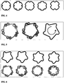
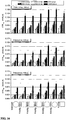
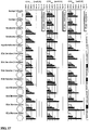
- FIGS. 5 to 7 show surface geometries that have emerged from theoretical considerations for meaningful implementation in a variety of geometric shapes. For all of these basic shapes circles of defined size were introduced whose radius was changed in 1 mm increments. The selection of the resulting geometries was based on a purely theoretical assessment of their influence on the flow in the cavity. Thus, forms with extremely strong or very weak buffers were excluded from consideration.
- Figures 6 and 7 show baffles starting from a five- or hexagonal base. Their construction is illustrated in Figures 6 and 7 by way of example. The corner of these bases were rounded off, taking as a radius for the corner circles one or two millimeters. At each corner, a semicircular chicane with a radius of 1 mm is created. This design dictates a direction of rotation for shaking due to the lack of symmetry for the cavities.
- FIG. 7 Further basic forms of cavities are shown. Starting from four-, five-, six- or seven-cornered basic shapes, the corners are again rounded, in which case the area between these corners is not flat but one having inwardly reaching peak. These peaks form the harassment in these cavities.
- FIG. 8 This in FIG. 8 shown array consists of different cavities and is used to investigate the performance of different geometries.
- each cavity tight against the environment and above each cavity has an opening which is designed so that the evaporation of the reaction liquid is greatly reduced and a transfer of material from the surrounding gas phase in the liquid in the cavity and in the opposite direction is not affected.
- individual or all reactors of a microreactor array are designed as Luer sleeves in relation to the Luer cores designed lids.
- Luer principle shown has proven to be very beneficial in this prototype. It is able to tightly seal the individual reaction chambers from the environment.
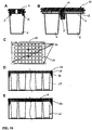
- the cavity 1 with a cover 2, which serves as a cover, closed.
- the lid 2 has conical fitting elements 3, which abut against the cavity wall and seal the lid 2 to the cavity 1.
- the lid 2 has a gas-permeable film 4, which is glued to the lid or welded to it. This film provides the necessary gas exchange, reduced evaporation and monoseptic operation. It is envisaged to pre-sterilize the microreactor array and fit lid components with final gas-permeable foil to the user.
- FIG. 10B Another embodiment is in FIG. 10B shown.
- a flexible sealing layer 7 is provided on the cavities 5, 6, on which a gas-permeable film 8 is located.
- the microreactor array has a conical cavity in the body which serves as a female luer sleeve 9.
- a cover 10 for the microreactor array has a luer core 11 which cooperates as a male part with the sleeve 9 and holds the cover on the array.
- the flexible layer 7 is mounted over the cavities. It seals by corresponding contact pressure of the lid, which seals all wells held by the Luer connection.
- the luer sleeves can be mounted, for example, between the individual wells and on the frame of the microreactor array. In Figure 10C a possible order is shown. Herein, the possible positions for luer sleeves are shown as attachment points 12 on the microreactor array 13 for sealing the cavities 14.
- the Figure 10D shows how the Luer principle can be exercised over the whole of the microreactor array.
- the array frame 15 are bevelled. They thus serve as Luer core for the lid 16, which either forms a circumferential Luer sleeve or is slipped over the sides of the array frame 15 only on the opposite sides.
- the array cover 16 is thus formed as a Luer sleeve and enters into a frictional connection with the array frame 15.
- a gas-permeable film 17 and a flexible cover layer 18 is provided between the cover 16 and the microreactor array frame in turn.
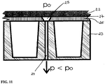
- FIG. 11 shows a variant in which the lid 22 is sucked onto the microreactor array 23 with vacuum or negative pressure.
- a vacuum 24 is drawn through a bore 24 in the body of the microreactor array 23, thus generating negative pressure, and the lid is drawn by a suction cup or a similar intermediate piece 25 to the microreactor array 23.
- the flexible layer 26 with the gas-permeable film 27 lying thereon is pressed onto the cavities in order to seal them.
- the pressing and sealing is active as long as vacuum is drawn or negative pressure is generated. Therefore, this connection is very easy to solve.
- the suction cups 25 and the holes 24 may be distributed as desired on the array depending on the application.
- FIG. 12A is shown as the lid 30 is fixed by a barb 31 on the plate geometry.
- the barb 31 hooks on a web 32.
- the lid 30 is held so close to the microreactor array 33 that it presses and thus seals the flexible layer 34 onto the cavities (not shown).
- FIG. 12B shows a variant in which the barb 35 in a. Nut 36 hooked in the microreactor array 37.
- FIG. 12D shows an alternative solution for attaching the cover 40 on the microreactor array 41 by applying a spring tension by means of the spring 42 on the barb 43. Only by applying an external force 44 by means of a gripping arm of a pipetting robot or manually, the tension of the spring 42nd be counteracted and the barbs 43 are spread. By moving the lid 40 down and then relieving the spring 42, the lid 40 can be placed and the barb on side bar 45 engage.
- FIG. 13 it is possible to have an overpressure inside the luer sleeve as in FIG. 13A shown to solve the luer connection.
- the overpressure can be applied through the hole in the Luer core by means of a compressed air line attached to the gripper arm of a pipetting robot.
- a compressed air line 51 must be guided to each Luer core 50.
- FIG. 13B shows how 52 pins 53 are mounted on a plate, which release the Luer cores 54 from below.
- the plate is simply placed on the pins 53 and already press the pins 53 guided through holes 55 in the microreactor array base body 56, the lid 57 on the Luer cores 54 upwards.
- FIG. 13C illustrates the in FIG. 13C illustrated construction.
- the force 60 is applied only to the outer frame 61 of the lid 62, are moved in the beveled shoes 63 as a finger of a gripping arm horizontally under the lid 62.
- the shoe 63 moves under the lid 62 and lifts him.
- the movement of the shoe 63 forces a relative movement of the microreactor array 65 to the lid 62 and releases it.
- FIG. 13D A slight modification of this principle shows the FIG. 13D , Here the shoe 66 is chamfered upwards.
- the cover 67 moves upwards via a slope 68, the microreactor array 69 remaining in its fixed position.
- FIG. 13E Another release mechanism is in Figure 13E shown. This release mechanism does without a special beveled shoe on the fingers of a gripper arm.
- FIG. 14 The arrangement shown has a cannula 80, which is guided through an opening 82 in a rigid lid back 83 through a gas-permeable film 84 and a flexible cover layer 85 in a cavity 86 to remove from the cavity 86 reaction liquid or to introduce into the cavity. Holes 87 are provided in the flexible covering layer 85 for material transport between inside and outside, which holes are aligned with openings 88 in the rigid cover back 83.
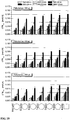
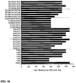
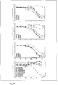
- another significant advantage of the invention is the prevention of the free-running of the bottom of the cavity.
- the fluorescence intensity of a fluorescein solution was used to calculate the layer thickness of the liquid at the bottom of a well during the rotation of the shaker.
- FIG. 19 The results described above show that the stronger the Corners and edges are pronounced, the more the liquid is prevented from expanding over the cavity walls and thus from the ground to soft.
- the novel design of the cover of the microtiter plate overcomes a serious disadvantage, which usually occurs in the cultivation in microtiter plates.
- the loss of fluid from the cavity occurring in particular at higher cultivation temperatures is markedly reduced.
- a sufficient gas exchange between environment and reaction volume is made possible.
- the invention offers the possibility of fitting the system in automated systems (pipetting robot, gripper arm) without large additional equipment or special applicators.
Landscapes
- Health & Medical Sciences (AREA)
- Chemical & Material Sciences (AREA)
- Wood Science & Technology (AREA)
- Organic Chemistry (AREA)
- Zoology (AREA)
- Life Sciences & Earth Sciences (AREA)
- Engineering & Computer Science (AREA)
- Bioinformatics & Cheminformatics (AREA)
- General Health & Medical Sciences (AREA)
- Clinical Laboratory Science (AREA)
- Genetics & Genomics (AREA)
- General Engineering & Computer Science (AREA)
- Microbiology (AREA)
- Sustainable Development (AREA)
- Biomedical Technology (AREA)
- Biotechnology (AREA)
- Biochemistry (AREA)
- Chemical Kinetics & Catalysis (AREA)
- Hematology (AREA)
- Analytical Chemistry (AREA)
- Apparatus Associated With Microorganisms And Enzymes (AREA)
- Physical Or Chemical Processes And Apparatus (AREA)
- Micromachines (AREA)
- Automatic Analysis And Handling Materials Therefor (AREA)
Claims (13)
- Microréacteur doté d'au moins une cavité qui présente un fond, une paroi latérale et une ouverture opposée au fond, dans lequel une section transversale coupant la paroi latérale parallèlement au fond à une forme différant d'une forme ronde, quadratique ou rectangulaire, caractérisé en ce que la forme de base de la section transversale est un polygone quelconque qui présente au moins un ou plusieurs segments de cercle concaves ou convexes, des cercles d'un rayon de plus de 0,5 mm étant réalisés aux angles du polygone.
- Microréacteur selon la revendication 1, caractérisé en ce que la section transversale présente plus de 3, de préférence plus de 4 arcs qui constituent respectivement un segment de cercle de plus de 90°.
- Microréacteur selon une des revendications précédentes, caractérisé en ce que la section transversale présente une zone dépassant dans la cavité ou dépassant hors de la cavité et que plusieurs zones de ces types à dimensions différentes sont prévues.
- Microréacteur selon une des revendications précédentes, caractérisé en ce qu 'une autre section coupant la paroi latérale parallèlement au fond présente une forme ronde, quadratique ou rectangulaire.
- Microréacteur selon une des revendications précédentes, caractérisé en ce qu' une pièce à section transversale variable est intégrée par le fond ou par un couvercle dans la cavité.
- Microréacteur selon une des revendications précédentes, caractérisé en ce que le fond est constitué d'un matériau optiquement transparent qui permet des mesures à travers le fond.
- Microréacteur selon une des revendications précédentes, caractérisé en ce qu 'il présente plusieurs cavités.
- Microréacteur selon une des revendications précédentes, caractérisé en ce qu 'il présente un couvercle.
- Microréacteur selon la revendication 10, caractérisé en ce que le couvercle présente une surface perméable au gaz.
- Microréacteur selon une des revendications 10 ou 11, caractérisé en ce que le couvercle présente une surface refermable.
- Microréacteur selon une des revendications précédentes, caractérisé en ce qu 'il constitue un élément du réseau de microréacteurs doté de plusieurs cavités similaires.
- Microréacteur selon une des revendications précédentes, caractérisé en ce qu 'il présente un dispositif de secouage.
- Microréacteur selon une des revendications précédentes, caractérisé en ce qu 'il permet un apport et une évacuation de participants à la réaction et un essai sans interrompre une opération de secouage.
Applications Claiming Priority (3)
| Application Number | Priority Date | Filing Date | Title |
|---|---|---|---|
| DE102007048201 | 2007-10-08 | ||
| DE102008008256A DE102008008256A1 (de) | 2007-10-08 | 2008-02-08 | Mikroreaktor |
| PCT/DE2008/001623 WO2009046697A2 (fr) | 2007-10-08 | 2008-10-08 | Microréacteur |
Publications (2)
| Publication Number | Publication Date |
|---|---|
| EP2205716A2 EP2205716A2 (fr) | 2010-07-14 |
| EP2205716B1 true EP2205716B1 (fr) | 2017-09-27 |
Family
ID=40418270
Family Applications (1)
| Application Number | Title | Priority Date | Filing Date |
|---|---|---|---|
| EP08837177.8A Active EP2205716B1 (fr) | 2007-10-08 | 2008-10-08 | Microréacteur |
Country Status (7)
| Country | Link |
|---|---|
| US (1) | US8828337B2 (fr) |
| EP (1) | EP2205716B1 (fr) |
| JP (1) | JP2011501689A (fr) |
| CN (1) | CN101932693B (fr) |
| DE (2) | DE102008008256A1 (fr) |
| DK (1) | DK2205716T3 (fr) |
| WO (1) | WO2009046697A2 (fr) |
Families Citing this family (19)
| Publication number | Priority date | Publication date | Assignee | Title |
|---|---|---|---|---|
| US10179928B2 (en) * | 2009-07-30 | 2019-01-15 | Helmholtz-Zentrum Fuer Infektionsforschung Gmbh | Methods and tests for screening bacterial biofilms |
| KR20120046738A (ko) * | 2009-09-05 | 2012-05-10 | 론자 바이올로직스 피엘씨 | 리드를 갖는 딥웰 플레이트 시스템 |
| DE102009057223B4 (de) * | 2009-12-05 | 2016-03-24 | Chemagen Biopolymer-Technologie Aktiengesellschaft | Probengefäßmatrix und deren Herstellungsverfahren |
| GB201103665D0 (en) * | 2011-03-04 | 2011-04-13 | Univ Cardiff | Correlative microscopy |
| US9333471B2 (en) | 2012-04-11 | 2016-05-10 | STAT—Diagnostica & Innovation, S.L. | Fluidically integrated magnetic bead beater |
| US9872448B2 (en) * | 2012-08-06 | 2018-01-23 | Council Of Scientific & Industrial Research | Bioreactor vessel for large scale growing of plants under aseptic condition |
| US9550972B2 (en) | 2014-09-29 | 2017-01-24 | General Electric Company | Devices, systems and methods for automated cell culturing |
| DE102016116377A1 (de) | 2016-09-01 | 2018-03-01 | Rheinisch-Westfälisch Technische Hochschule (RWTH) Aachen | Verfahren und Vorrichtung zur Erfassung von Prozessparametern in Flüssigkulturen |
| WO2018136752A2 (fr) * | 2017-01-19 | 2018-07-26 | Essen Bioscience, Inc. | Procédés et appareil de contrôle de perfusion et d'environnement de matériel de laboratoire du type microplaque |
| WO2018144161A1 (fr) * | 2017-01-31 | 2018-08-09 | Counsyl, Inc. | Système de diagnostic automatique à haut débit pour retirer des couvercles de microplaques |
| GB201709140D0 (en) * | 2017-06-08 | 2017-07-26 | Vitrolife As | Lid for culture dish |
| JP7212028B2 (ja) * | 2017-07-13 | 2023-01-24 | グライナー バイオ‐ワン ノース アメリカ,インコーポレイテッド | 撮像用の培養プレート |
| DE102018112895B4 (de) | 2018-05-30 | 2024-05-08 | Presens Precision Sensing Gmbh | System, Vorrichtung und Verfahren zur Erfassung mindestens einer Veränderlichen während eines biologisch / chemischen Prozesses |
| CN110907420B (zh) * | 2019-12-04 | 2021-07-02 | 中国科学院过程工程研究所 | 一种不互溶液-液相间传质平衡时间的测量装置及利用其的测量方法 |
| EP3910051A1 (fr) | 2020-05-13 | 2021-11-17 | Evonik Operations GmbH | Bioréacteurs d'agitation orbitale de cultures cellulaires, en particulier des cultures de suspension |
| EP3995211A1 (fr) * | 2020-11-10 | 2022-05-11 | National Health Research Institutes | Procédé de collecte de cellule unique à haut rendement |
| CA3218174A1 (fr) | 2021-05-07 | 2022-11-10 | Beckman Coulter, Inc. | Ensemble recipient pour microbioreacteur |
| WO2022235597A1 (fr) | 2021-05-07 | 2022-11-10 | Beckman Coulter, Inc. | Régulation du ph dans des puits de culture parallèles |
| EP4334429A1 (fr) | 2021-05-07 | 2024-03-13 | Beckman Coulter, Inc. | Ensemble récipient pour microbioréacteur |
Citations (1)
| Publication number | Priority date | Publication date | Assignee | Title |
|---|---|---|---|---|
| WO2009013869A1 (fr) * | 2007-07-25 | 2009-01-29 | Panasonic Corporation | Biocapteur |
Family Cites Families (20)
| Publication number | Priority date | Publication date | Assignee | Title |
|---|---|---|---|---|
| US5225164A (en) * | 1991-09-30 | 1993-07-06 | Astle Thomas W | Microplate laboratory tray with rectilinear wells |
| EP0973863B1 (fr) * | 1997-04-09 | 2005-05-25 | Minnesota Mining And Manufacturing Company | Procede et dispositifs pour diviser des liquides d'echantillons biologiques en microvolumes |
| USD403077S (en) * | 1997-05-12 | 1998-12-22 | Neogen Corporation | Microorganism culture tray |
| US6159368A (en) * | 1998-10-29 | 2000-12-12 | The Perkin-Elmer Corporation | Multi-well microfiltration apparatus |
| US6896848B1 (en) | 2000-12-19 | 2005-05-24 | Tekcel, Inc. | Microplate cover assembly |
| DE10117275B4 (de) * | 2001-04-06 | 2005-02-24 | Hte Ag The High Throughput Experimentation Company | Vorrichtung zur Archivierung und Analyse von Materialien |
| WO2002102965A2 (fr) | 2001-06-14 | 2002-12-27 | Millipore Corporation | Appareil d'analyse a puits multiples |
| AT500167B1 (de) * | 2001-06-18 | 2007-10-15 | Greiner Bio One Gmbh | Reaktionsgefäss |
| US6890488B2 (en) * | 2001-06-22 | 2005-05-10 | Matrix Technologies, Inc. | Apparatus for sealing test tubes and the like |
| DE20121739U1 (de) * | 2001-10-08 | 2003-08-28 | Mecadi Gmbh Chemicals Proc | Platte für parallelisierte Analysen und Synthesen |
| DE10159091A1 (de) * | 2001-12-01 | 2003-06-12 | Evotec Ag | Trägersysteme und Verfahren zu ihrer Herstellung |
| AU2003228711C1 (en) * | 2002-04-26 | 2010-01-07 | Board Of Regents, The University Of Texas System | Method and system for the detection of cardiac risk factors |
| JP2003344433A (ja) * | 2002-05-22 | 2003-12-03 | Okutekku:Kk | マイクロアレイ、マイクロアレイシステム及び被検物質の測定方法 |
| US7211224B2 (en) * | 2002-05-23 | 2007-05-01 | Millipore Corporation | One piece filtration plate |
| EP1508373A3 (fr) * | 2003-08-19 | 2005-08-03 | Herbener, Heinz-Gerd | porte-échantillon avec canal pour fluides |
| DE102004017039A1 (de) | 2004-04-02 | 2005-11-03 | Rwth Aachen | Verfahren und Vorrichtung zur Erfassung von Prozessparametern von Reaktionsflüssigkeiten in mehreren geschüttelten Mikroreaktoren |
| JP3978500B2 (ja) * | 2005-02-18 | 2007-09-19 | 国立大学法人埼玉大学 | 多種微量試料の注入、移行方法 |
| DE202006004642U1 (de) * | 2005-03-29 | 2006-06-08 | Sartorius Ag | Mikroarray-Vorrichtung zum Präparieren eines Probenträgers |
| US20060286003A1 (en) * | 2005-06-16 | 2006-12-21 | Desilets Kenneth G | Multi-well filter plate with shifted wells and U-bottom receiver plate |
| EP1944080A1 (fr) * | 2007-01-11 | 2008-07-16 | F.Hoffmann-La Roche Ag | Appareil et procédé pour mouvement d'un liquide dans une cavité |
-
2008
- 2008-02-08 DE DE102008008256A patent/DE102008008256A1/de not_active Withdrawn
- 2008-10-08 US US12/734,054 patent/US8828337B2/en active Active
- 2008-10-08 WO PCT/DE2008/001623 patent/WO2009046697A2/fr active Application Filing
- 2008-10-08 DK DK08837177.8T patent/DK2205716T3/en active
- 2008-10-08 CN CN2008801192016A patent/CN101932693B/zh active Active
- 2008-10-08 JP JP2010527321A patent/JP2011501689A/ja active Pending
- 2008-10-08 DE DE112008002590.8T patent/DE112008002590B4/de active Active
- 2008-10-08 EP EP08837177.8A patent/EP2205716B1/fr active Active
Patent Citations (1)
| Publication number | Priority date | Publication date | Assignee | Title |
|---|---|---|---|---|
| WO2009013869A1 (fr) * | 2007-07-25 | 2009-01-29 | Panasonic Corporation | Biocapteur |
Also Published As
| Publication number | Publication date |
|---|---|
| US8828337B2 (en) | 2014-09-09 |
| JP2011501689A (ja) | 2011-01-13 |
| EP2205716A2 (fr) | 2010-07-14 |
| DE112008002590B4 (de) | 2022-02-24 |
| DE102008008256A1 (de) | 2009-04-09 |
| DE112008002590A5 (de) | 2010-06-24 |
| WO2009046697A9 (fr) | 2009-07-23 |
| CN101932693B (zh) | 2013-03-27 |
| CN101932693A (zh) | 2010-12-29 |
| WO2009046697A2 (fr) | 2009-04-16 |
| US20100248995A1 (en) | 2010-09-30 |
| DK2205716T3 (en) | 2017-12-04 |
| WO2009046697A3 (fr) | 2009-09-11 |
Similar Documents
| Publication | Publication Date | Title |
|---|---|---|
| EP2205716B1 (fr) | Microréacteur | |
| EP2038062B1 (fr) | Réseau de microréacteurs, dispositif muni d'un réseau de microréacteurs et procédé pour utiliser un réseau de microréacteurs | |
| DE60211155T2 (de) | Mehrfachlochtestvorrichtung | |
| DE69831408T2 (de) | Filterplatte | |
| EP1718409B1 (fr) | Dispositif utilise pour effectuer des analyses microscopiques de fluides | |
| EP2192984B1 (fr) | Système microfluidique partiellement actif pour la culture cellulaire en 3d et procédé pour sa perfusion | |
| EP1110609B1 (fr) | Système de traitement d'échantillons dans un dispositif à compartiments multiples | |
| DE602004010474T2 (de) | Behälter zur Kultivierung von Geweben | |
| EP1173541B1 (fr) | Dispositif pour effectuer des analyses sur des cultures cellulaires | |
| DE19950809B4 (de) | Verfahren und Vorrichtung für eine Flüssigkeitsübertragung | |
| EP1083992B1 (fr) | Support de reacteur a plusieurs chambres de reception de microechantillons | |
| DE19948087B4 (de) | Verfahren zur Herstellung eines Reaktionssubstrats | |
| DE60309962T2 (de) | Einteilige Filterplatte | |
| WO2015051776A1 (fr) | Système de microréacteur | |
| EP1879995B1 (fr) | Procede de fermentation et dispositif associe | |
| EP2024744A1 (fr) | Plaque microtitre et son utilisation | |
| EP2604342B1 (fr) | Chambre d'analyse dotée d'une plaque de séparation | |
| DE10118905A1 (de) | Verfahren und Vorrichtung zum Kultivieren und/oder Verteilen von Partikeln | |
| EP1397201B2 (fr) | Recipient de reaction servant a produire des echantillons | |
| EP3129459A1 (fr) | Dispositif de mélange pour le mélange du contenu d'un récipient | |
| DE102020107599B3 (de) | Verfahren zur Kultivierung von Zellen | |
| EP1222028B1 (fr) | Plaque de support destinee a recevoir de maniere ordonnee des particules d'echantillon | |
| EP1358926B1 (fr) | Dispositifs d'échange gazeux et la séparation de matières biologique ou la séparation de mélanges de substances et l'utilisation de nanocomposites | |
| DE102007041071B4 (de) | Vorrichtung zur Aufnahme einer Flüssigkeit sowie Vorrichtung zur Aufbringung von Flüssigkeiten auf Probenträger und Verfahren hierzu | |
| DE102021006144A1 (de) | Reaktionsgefäßeinheit, Verfahren zum selektiven Entfernen einer Flüssigkeit sowie zum Einbringen einer einen Zielstoff enthaltenden Flüssigkeit aus einem bzw. in ein Reaktionsgefäß einer Reaktionsgefäßeinheit |
Legal Events
| Date | Code | Title | Description |
|---|---|---|---|
| PUAI | Public reference made under article 153(3) epc to a published international application that has entered the european phase |
Free format text: ORIGINAL CODE: 0009012 |
|
| 17P | Request for examination filed |
Effective date: 20100503 |
|
| AK | Designated contracting states |
Kind code of ref document: A2 Designated state(s): AT BE BG CH CY CZ DE DK EE ES FI FR GB GR HR HU IE IS IT LI LT LU LV MC MT NL NO PL PT RO SE SI SK TR |
|
| AX | Request for extension of the european patent |
Extension state: AL BA MK RS |
|
| RIN1 | Information on inventor provided before grant (corrected) |
Inventor name: FUNKE, MATTHIAS Inventor name: BUECHS, JOCHEN Inventor name: KENSY, FRANK Inventor name: MUELLER, CARSTEN |
|
| DAX | Request for extension of the european patent (deleted) | ||
| RAP1 | Party data changed (applicant data changed or rights of an application transferred) |
Owner name: M2P-LABS GMBH |
|
| 17Q | First examination report despatched |
Effective date: 20160930 |
|
| STAA | Information on the status of an ep patent application or granted ep patent |
Free format text: STATUS: EXAMINATION IS IN PROGRESS |
|
| REG | Reference to a national code |
Ref country code: DE Ref legal event code: R079 Ref document number: 502008015651 Country of ref document: DE Free format text: PREVIOUS MAIN CLASS: C12M0003040000 Ipc: B01F0011000000 |
|
| GRAP | Despatch of communication of intention to grant a patent |
Free format text: ORIGINAL CODE: EPIDOSNIGR1 |
|
| STAA | Information on the status of an ep patent application or granted ep patent |
Free format text: STATUS: GRANT OF PATENT IS INTENDED |
|
| RIC1 | Information provided on ipc code assigned before grant |
Ipc: B01L 3/00 20060101ALI20170428BHEP Ipc: C12M 1/04 20060101ALI20170428BHEP Ipc: C12M 1/32 20060101ALI20170428BHEP Ipc: B01F 15/00 20060101ALI20170428BHEP Ipc: B01F 11/00 20060101AFI20170428BHEP Ipc: C12M 1/00 20060101ALI20170428BHEP |
|
| INTG | Intention to grant announced |
Effective date: 20170515 |
|
| GRAS | Grant fee paid |
Free format text: ORIGINAL CODE: EPIDOSNIGR3 |
|
| GRAA | (expected) grant |
Free format text: ORIGINAL CODE: 0009210 |
|
| STAA | Information on the status of an ep patent application or granted ep patent |
Free format text: STATUS: THE PATENT HAS BEEN GRANTED |
|
| AK | Designated contracting states |
Kind code of ref document: B1 Designated state(s): AT BE BG CH CY CZ DE DK EE ES FI FR GB GR HR HU IE IS IT LI LT LU LV MC MT NL NO PL PT RO SE SI SK TR |
|
| REG | Reference to a national code |
Ref country code: GB Ref legal event code: FG4D Free format text: NOT ENGLISH |
|
| REG | Reference to a national code |
Ref country code: CH Ref legal event code: EP |
|
| REG | Reference to a national code |
Ref country code: AT Ref legal event code: REF Ref document number: 931478 Country of ref document: AT Kind code of ref document: T Effective date: 20171015 |
|
| REG | Reference to a national code |
Ref country code: IE Ref legal event code: FG4D Free format text: LANGUAGE OF EP DOCUMENT: GERMAN |
|
| REG | Reference to a national code |
Ref country code: DE Ref legal event code: R096 Ref document number: 502008015651 Country of ref document: DE |
|
| REG | Reference to a national code |
Ref country code: DK Ref legal event code: T3 Effective date: 20171129 |
|
| REG | Reference to a national code |
Ref country code: FR Ref legal event code: PLFP Year of fee payment: 10 |
|
| REG | Reference to a national code |
Ref country code: CH Ref legal event code: NV Representative=s name: MICHELI AND CIE SA, CH |
|
| PG25 | Lapsed in a contracting state [announced via postgrant information from national office to epo] |
Ref country code: NO Free format text: LAPSE BECAUSE OF FAILURE TO SUBMIT A TRANSLATION OF THE DESCRIPTION OR TO PAY THE FEE WITHIN THE PRESCRIBED TIME-LIMIT Effective date: 20171227 Ref country code: HR Free format text: LAPSE BECAUSE OF FAILURE TO SUBMIT A TRANSLATION OF THE DESCRIPTION OR TO PAY THE FEE WITHIN THE PRESCRIBED TIME-LIMIT Effective date: 20170927 Ref country code: SE Free format text: LAPSE BECAUSE OF FAILURE TO SUBMIT A TRANSLATION OF THE DESCRIPTION OR TO PAY THE FEE WITHIN THE PRESCRIBED TIME-LIMIT Effective date: 20170927 Ref country code: FI Free format text: LAPSE BECAUSE OF FAILURE TO SUBMIT A TRANSLATION OF THE DESCRIPTION OR TO PAY THE FEE WITHIN THE PRESCRIBED TIME-LIMIT Effective date: 20170927 Ref country code: LT Free format text: LAPSE BECAUSE OF FAILURE TO SUBMIT A TRANSLATION OF THE DESCRIPTION OR TO PAY THE FEE WITHIN THE PRESCRIBED TIME-LIMIT Effective date: 20170927 |
|
| REG | Reference to a national code |
Ref country code: NL Ref legal event code: MP Effective date: 20170927 |
|
| REG | Reference to a national code |
Ref country code: LT Ref legal event code: MG4D |
|
| PG25 | Lapsed in a contracting state [announced via postgrant information from national office to epo] |
Ref country code: BG Free format text: LAPSE BECAUSE OF FAILURE TO SUBMIT A TRANSLATION OF THE DESCRIPTION OR TO PAY THE FEE WITHIN THE PRESCRIBED TIME-LIMIT Effective date: 20171227 Ref country code: LV Free format text: LAPSE BECAUSE OF FAILURE TO SUBMIT A TRANSLATION OF THE DESCRIPTION OR TO PAY THE FEE WITHIN THE PRESCRIBED TIME-LIMIT Effective date: 20170927 Ref country code: GR Free format text: LAPSE BECAUSE OF FAILURE TO SUBMIT A TRANSLATION OF THE DESCRIPTION OR TO PAY THE FEE WITHIN THE PRESCRIBED TIME-LIMIT Effective date: 20171228 |
|
| PG25 | Lapsed in a contracting state [announced via postgrant information from national office to epo] |
Ref country code: NL Free format text: LAPSE BECAUSE OF FAILURE TO SUBMIT A TRANSLATION OF THE DESCRIPTION OR TO PAY THE FEE WITHIN THE PRESCRIBED TIME-LIMIT Effective date: 20170927 |
|
| PG25 | Lapsed in a contracting state [announced via postgrant information from national office to epo] |
Ref country code: CZ Free format text: LAPSE BECAUSE OF FAILURE TO SUBMIT A TRANSLATION OF THE DESCRIPTION OR TO PAY THE FEE WITHIN THE PRESCRIBED TIME-LIMIT Effective date: 20170927 Ref country code: ES Free format text: LAPSE BECAUSE OF FAILURE TO SUBMIT A TRANSLATION OF THE DESCRIPTION OR TO PAY THE FEE WITHIN THE PRESCRIBED TIME-LIMIT Effective date: 20170927 Ref country code: RO Free format text: LAPSE BECAUSE OF FAILURE TO SUBMIT A TRANSLATION OF THE DESCRIPTION OR TO PAY THE FEE WITHIN THE PRESCRIBED TIME-LIMIT Effective date: 20170927 |
|
| PG25 | Lapsed in a contracting state [announced via postgrant information from national office to epo] |
Ref country code: SK Free format text: LAPSE BECAUSE OF FAILURE TO SUBMIT A TRANSLATION OF THE DESCRIPTION OR TO PAY THE FEE WITHIN THE PRESCRIBED TIME-LIMIT Effective date: 20170927 Ref country code: EE Free format text: LAPSE BECAUSE OF FAILURE TO SUBMIT A TRANSLATION OF THE DESCRIPTION OR TO PAY THE FEE WITHIN THE PRESCRIBED TIME-LIMIT Effective date: 20170927 Ref country code: IS Free format text: LAPSE BECAUSE OF FAILURE TO SUBMIT A TRANSLATION OF THE DESCRIPTION OR TO PAY THE FEE WITHIN THE PRESCRIBED TIME-LIMIT Effective date: 20180127 |
|
| REG | Reference to a national code |
Ref country code: DE Ref legal event code: R097 Ref document number: 502008015651 Country of ref document: DE |
|
| PG25 | Lapsed in a contracting state [announced via postgrant information from national office to epo] |
Ref country code: MC Free format text: LAPSE BECAUSE OF FAILURE TO SUBMIT A TRANSLATION OF THE DESCRIPTION OR TO PAY THE FEE WITHIN THE PRESCRIBED TIME-LIMIT Effective date: 20170927 |
|
| REG | Reference to a national code |
Ref country code: IE Ref legal event code: MM4A |
|
| PG25 | Lapsed in a contracting state [announced via postgrant information from national office to epo] |
Ref country code: LU Free format text: LAPSE BECAUSE OF NON-PAYMENT OF DUE FEES Effective date: 20171008 |
|
| PLBE | No opposition filed within time limit |
Free format text: ORIGINAL CODE: 0009261 |
|
| STAA | Information on the status of an ep patent application or granted ep patent |
Free format text: STATUS: NO OPPOSITION FILED WITHIN TIME LIMIT |
|
| REG | Reference to a national code |
Ref country code: BE Ref legal event code: MM Effective date: 20171031 |
|
| PG25 | Lapsed in a contracting state [announced via postgrant information from national office to epo] |
Ref country code: PL Free format text: LAPSE BECAUSE OF FAILURE TO SUBMIT A TRANSLATION OF THE DESCRIPTION OR TO PAY THE FEE WITHIN THE PRESCRIBED TIME-LIMIT Effective date: 20170927 Ref country code: BE Free format text: LAPSE BECAUSE OF NON-PAYMENT OF DUE FEES Effective date: 20171031 |
|
| 26N | No opposition filed |
Effective date: 20180628 |
|
| PG25 | Lapsed in a contracting state [announced via postgrant information from national office to epo] |
Ref country code: MT Free format text: LAPSE BECAUSE OF FAILURE TO SUBMIT A TRANSLATION OF THE DESCRIPTION OR TO PAY THE FEE WITHIN THE PRESCRIBED TIME-LIMIT Effective date: 20170927 |
|
| REG | Reference to a national code |
Ref country code: FR Ref legal event code: PLFP Year of fee payment: 11 |
|
| PG25 | Lapsed in a contracting state [announced via postgrant information from national office to epo] |
Ref country code: IE Free format text: LAPSE BECAUSE OF NON-PAYMENT OF DUE FEES Effective date: 20171008 |
|
| PG25 | Lapsed in a contracting state [announced via postgrant information from national office to epo] |
Ref country code: SI Free format text: LAPSE BECAUSE OF FAILURE TO SUBMIT A TRANSLATION OF THE DESCRIPTION OR TO PAY THE FEE WITHIN THE PRESCRIBED TIME-LIMIT Effective date: 20170927 |
|
| REG | Reference to a national code |
Ref country code: AT Ref legal event code: MM01 Ref document number: 931478 Country of ref document: AT Kind code of ref document: T Effective date: 20171008 |
|
| PG25 | Lapsed in a contracting state [announced via postgrant information from national office to epo] |
Ref country code: AT Free format text: LAPSE BECAUSE OF NON-PAYMENT OF DUE FEES Effective date: 20171008 |
|
| PG25 | Lapsed in a contracting state [announced via postgrant information from national office to epo] |
Ref country code: HU Free format text: LAPSE BECAUSE OF FAILURE TO SUBMIT A TRANSLATION OF THE DESCRIPTION OR TO PAY THE FEE WITHIN THE PRESCRIBED TIME-LIMIT; INVALID AB INITIO Effective date: 20081008 |
|
| PG25 | Lapsed in a contracting state [announced via postgrant information from national office to epo] |
Ref country code: CY Free format text: LAPSE BECAUSE OF NON-PAYMENT OF DUE FEES Effective date: 20170927 |
|
| PG25 | Lapsed in a contracting state [announced via postgrant information from national office to epo] |
Ref country code: TR Free format text: LAPSE BECAUSE OF FAILURE TO SUBMIT A TRANSLATION OF THE DESCRIPTION OR TO PAY THE FEE WITHIN THE PRESCRIBED TIME-LIMIT Effective date: 20170927 |
|
| PG25 | Lapsed in a contracting state [announced via postgrant information from national office to epo] |
Ref country code: PT Free format text: LAPSE BECAUSE OF FAILURE TO SUBMIT A TRANSLATION OF THE DESCRIPTION OR TO PAY THE FEE WITHIN THE PRESCRIBED TIME-LIMIT Effective date: 20170927 |
|
| REG | Reference to a national code |
Ref country code: DE Ref legal event code: R079 Ref document number: 502008015651 Country of ref document: DE Free format text: PREVIOUS MAIN CLASS: B01F0011000000 Ipc: B01F0031000000 |
|
| PGFP | Annual fee paid to national office [announced via postgrant information from national office to epo] |
Ref country code: IT Payment date: 20230913 Year of fee payment: 16 Ref country code: GB Payment date: 20230817 Year of fee payment: 16 |
|
| PGFP | Annual fee paid to national office [announced via postgrant information from national office to epo] |
Ref country code: FR Payment date: 20230821 Year of fee payment: 16 |
|
| PGFP | Annual fee paid to national office [announced via postgrant information from national office to epo] |
Ref country code: DK Payment date: 20231016 Year of fee payment: 16 Ref country code: DE Payment date: 20230822 Year of fee payment: 16 Ref country code: CH Payment date: 20231102 Year of fee payment: 16 |